IS (Image Stabilization) User Guide
REVISION HISTORY
| Revision No. | Description |
Date |
|---|---|---|
| 1.0 | 10/09/2023 | |
| 01/10/2024 | ||
| 03/26/2024 | ||
int (*early_init)(struct gyro_dev * dev); int (*final_deinit)(struct gyro_dev * dev); int (*get_group_delay)(struct gyro_dev *dev, struct gyro_arg_group_delay * delay); int (*get_noise_bandwidth)(struct gyro_dev *dev, struct gyro_arg_noise_bandwidth *nbw); |
05/30/2024 | |
| 06/19/2024 | ||
| 07/11/2024 | ||
| 10/15/2024 | ||
| 08/11/2025 | ||
| 09/22/2025 |
1. OVERVIEW
Due to various possible factors, the video captured by the camera is prone to jitter, which affects video quality. To enhance video stability and improve its quality, image stabilization processing is required. Currently, the image stabilization processing supports DIS-GME, DIS-GYRO and DIS-CUST modes. A detailed introduction of the two modes is set out below.
2. DIS-GME WORKING MODE
2.1 Basic Ideas
The DIS-GME image stabilization mode refers to Digital Image Stabilization (DIS), which is different from mechanical, optical, or electronic anti-shake processing. The DIS-GME uses image features to perform geometric transformation against the video frames that cause jitter, thereby preventing shaking effect.
2.2 Basic Principle
When video jitters, it means that there is motion offset occurring between video frames. The motion offset can be described by a two-dimensional transformation model below:
In the model above, (x,y) represents the coordinates of the original image, and 3\times3 matrix H represents the information of motion offset, while ({\Large \frac{u}{w}}, {\Large \frac{v}{w}} ) represents the image coordinates after offset.
The basic principle of DIS is to use adjacent video frames to calculate the matrix H, and then perform motion compensation to remove the offset based on the matrix H. After motion compensation is performed on the video frame, however, an empty content area will be generated. In order to remove the empty content area, the video frame needs to be cropped and enlarged to display the common content area between adjacent frames.

Basic Principle of DIS |
2.3 Tuning Guide
2.3.1 Video Quality and Application Scenario Requirements
In order to achieve ideal DIS effects, video quality and application scenarios should meet the following requirements.
2.3.1.1 Rolling Shutter
The Rolling Shutter of the input video will affect DIS effect, so system parameters (such as exposure time, etc.) should be properly adjusted to control the Rolling Shutter within an acceptable range.
2.3.1.2 Video Clarity
Motion blur caused by camera shaking will affect the image feature detection by DIS, resulting in inaccurate matrix calculation. It will also cause image smearing or ghosting in the final output result. Therefore, it is necessary to adjust the image quality (IQ) to ensure that video frames can be clear and stable without motion blur no matter camera is in still or shaking conditions. The picture below shows before and after IQ adjustment when the camera jittersshakes.

Video Frame with Motion Blur Before IQ Adjustment |
Clear Video Frame After IQ Adjustment |
2.3.1.3 Distortion
Video distortion also affects the DIS effect. It is recommended to use lens with as little distortion as possible or perform lens distortion calibration to eliminate the impact of video distortion on the DIS effect. The picture below shows before and after distortion calibration.

Distorted Video Frame |

Video Frame After Distortion Calibration |
2.3.1.4 Parallax
Scenes with large parallax (that is, there is a significant depth difference between the foreground and background) may cause distortion in DIS video output. Therefore, it is not recommended to apply DIS in scenes with large parallax.
Video Frame with Large Parallax |
2.3.1.5 Low Luminance Scene
Within a certain range of low luminance, DIS can still work normally. However, in extremely low-luminance environments, DIS will not be able to detect feature points, resulting in poor DIS effect. Therefore, it is not recommended that you use DIS in extremely low-luminance environments, as the following example demonstrates:

Video Frame in Extremely Low-Luminance |
Precaution:
When streaming starts, the ISP module will converge and drop 10 pictures by default. This process represents the process from dark to bright. If the number of convergence times is not enough, the information of picture brightness sent to the DIS module may change (sometimes it may still be very dark), as shown below:
|
Video Frame in Extremely Low-Luminance during ISP Convergence |
Video Frame in Low-Luminance during ISP Convergence |
2.3.1.6 Video Aspect Ratio
The image stabilization module normally supports videos in 16:9. For videos in 9:16, the effect may be slightly affected.
2.3.2 Parameter Configuration
2.3.2.1 eMode
Mode of DIS algorithm.
| Member Names | Description |
|---|---|
| MI_LDC_DIS_GME_6DOF | Six degrees of freedom of image stability, no gyroscope is used. |
| MI_LDC_DIS_GME_8DOF (Default) | Eight degrees of freedom of image stability, no gyroscope is used. |
DIS is an inverse transformation of the frame that produces jitter (geometric transformation). The image transformations supported by six degrees of freedom of image stability include translation, rotation, scaling, stretching, and cropping. Image transformations supported by eight degrees of freedom of image stability include translation, rotation, scaling, stretching, cropping and perspective. In some scenes with complex jitter, 8-DOF image stability will be more effective than 6-DOF image stability, but the amount of calculation will also increase.
2.3.2.2 eSceneType
The type of DIS application scene.
| Member Names | Description |
|---|---|
| MI_LDC_DIS_FIX_SCENE (Default) | Still scene, such as security surveillance camera that is fixed to the building. |
| MI_LDC_DIS_MOVE_SCENE | Motion scene, such as hand-held, vehicle-mounted or aircraft cameras. |
2.3.2.3 u8CropRatio
For the cropping ratio of DIS output image, the value range is [50, 98]. In other words, the proportion of the retained image after cropping is 50% ~ 98%. The default cropping ratio is 70. In other words, if the input image width and height are 1920×1080, the cropped image width will be 1920×70%=1344 and the height will be 1080×70%=756.
Generally speaking, the greater the video jitter range, the smaller the shared content area between adjacent frames will be. In order to maintain a better anti-shake effect, u8CropRatio needs to be set smaller. But if u8CropRatio is too small, too much field of view will be lost. Therefore, the setting of u8CropRatio should be adjusted according to the jitter range in the actual scene, in a bid to balance the image stability and the size of field of view.
2.3.2.4 eMotionLevel
The level of camera jittering magnitude.
| Member Names | Description |
|---|---|
| MI_LDC_DIS_MOTION_LEVEL0 | Smaller jittering magnitude. |
| MI_LDC_DIS_MOTION_LEVEL1 (Default) | Greater jittering magnitude. |
2.3.3 Trouble Shooting
When the DIS effect deteriorates or a warning is output, please follow the following process to troubleshoot.
2.3.3.1 Checking Input Video Quality and Scenes
| Phenomenon | Possible Reasons and Solution |
|---|---|
| Flicker and ghosting appear in the output video. | Check the input video frame by frame to see if motion blur occurs. If there is motion blur, you need to adjust the IQ to eliminate it. |
| Anti-shaking is not effective, or distortion occurs in the output video. | 1. Check whether the scene in the input video lacks features (extremely low illumination, large object occlusion, etc. may lead to lack of features) 2. Check whether there is an obvious depth difference between the foreground and background in the input video (large parallax) 3. Check whether there is a large motion in the foreground of the input jittered video. 4. Check whether the input video has obvious rolling shutter. (The deterioration of the DIS effect caused by the above reasons is an inherent flaw of the algorithm, which should be considered normal phenomenons) |
2.3.3.2 Checking Parameter Configuration
After the possible causes above have been eliminated, check whether the parameter settings are reasonable. Please refer to "2.3.2 Parameter Configuration". In addition, please follow the default configuration for the unopened parameters.
3. DIS-GYRO WORKING MODE
3.1 Basic Ideas
The DIS-GYRO image stabilization mode refers to Electronic Image Stabilization (EIS), which uses gyroscope algorithm based on the data generated by the gyroscope to calculate the motion offset of the current frame, and to perform geometric transformation to achieve anti-shake/image stabilizing effect.
Currently, EIS supports compensation of the X, Y, and Z axes (rotation of the X/Y/Z axis), and supports superimposed distortion calibration.
3.2 Basic Principle
The principle of EIS is to eliminate image instability caused by camera shake by compensating and calibrating the image during image processing. The general EIS work flow is as follows:
- Sense shake: Sensors such as accelerometers or gyroscopes inside the camera monitor the shaking or movement of the camera;
- Store images: The camera will keep capturing images and storing them in the buffer, usually in the form of consecutive frames;
- Analyze images: By analyzing consecutive image frames, EIS detects camera shaking and movement trajectories;
- Compensation and calibration: Based on the shake and movement data, EIS will compensate and calibrate the image. It calculates the offset amount of camera and compensates for the offset and distortion of the image during image processing;
- Produce stable images: By compensating and calibrating images, EIS can generate more stable images and reduce the impact of hand shaking on image quality.

EIS Effect |
3.3 TUNING GUIDE
3.3.1 Gyro Driver Adaptation of Customized Model
The kernel source code provided by SigmaStar features a common framework for Gyro Driver, by which customers can add gyroscope driver code of corresponding models on the basis of this framework.
3.3.1.1 Gyro Driver Framework

Gyro Driver Framework |
The structure of Gyro Driver Framework is shown in the above figure. The structure can be divided into three parts:
-
Major Stucture
The core of Gyro Driver, composed by the following five files:
File Description Note gyro_module.c This file will complete the initialization and de-initialization of the required configurations (gyro_core, gyro_sensor_xxx, gyro_i2c/spi) and optional configurations (ioctl chrdev and sysfs node) in the module_init and module_exit stages based on the API provided by the lower layer. This file does not require customer modification. gyro_core.c This file represents the middle layer, which mainly constructs a series of Gyro Sensor Operation APIs. This middle layer provides a unified Function Callback to the lower layer for instantiation, and a unified API to the upper layer for the initialization as well as related hardware operations of the Gyro Sensor. This file does not require customer modification. gyro_manager.c This file is a middle layer, which mainly manages three types of resources: transfer, sensor, and device. It provides macro-defined interfaces, determines the specific transfer and sensor resources required during compilation, and provides APIs to attach and detach devices to/from sensor and transfer resources when the interface drv-dev is probed/removed. This file does not require customer modification. gyro_control_group.c This file serves as an intermediate layer, mainly managing user information for each device, including but not limited to read/write permission controls and FIFO resources shared between writers and readers. - If device resources are used with write permission (Under DIS_GYRO working mode, it is occupied by default), the write permission flag must be configured when opening the file descriptor (fd), and related read/write permission ioctls can be operated, but only one writer is allowed at the same time.
- If device resources are used with read permission, the read permission flag must be configured when opening the fd, and only related read permission ioctls can be operated, allowing multiple readers at the same time.
This file does not need to be modified by the client. gyro_sensor_icg20660/icm40607.c This file contains the specific differentiation of each model, and the difference is mainly reflected by Register Setting. It will implement the Function Callback required in gyro_core.h. If customers need to transplant other models of Gyro Sensor, they can compile in reference to the codes of the icg20660 and icm40607 models used in the public version. This file requires customer modification. gyro_i2c/spi.c This file is the transport layer. You can use I2C or SPI to read and write the Gyro Sensor Register according to the configuration of menuconfig. This file does not require customer modification. -
ioctl chrdev
ioctl chrdev mainly provides the ioctl interface for user space. The corresponding API of gyro_core.c will be called according to ioctl number.
-
sysfs node
A set of simple functional code for testing Gyro Sensor provided by the company.
3.3.1.2 Gyro Driver Ioctl Interface
The definition of Ioctl Number is in kernel/drivers/sstar/include/gyro_ioctl.h. The following is its introduction:
| Ioctl Number Macro | Function | Parameter Type | Parameter Prototype Description |
|---|---|---|---|
| GYRO_IOC_CMD_SET_SAMPLE_RATE | Set frequency division of the clock. For example, the icg20660 used in reference board supports settings of 500 and 1000Hz. | gyro_arg_sample_rate_t * | typedef struct gyro_arg_sample_rate { unsigned int rate; } gyro_arg_sample_rate_t; The rate member in this structure is frequency division, and the unit is Hz. |
| GYRO_IOC_CMD_SET_GYRO_RANGE | Set the measuring range of the gyro sensor. For example, the icg20660 used in reference board supports settings of ±125, ±250, ±500 °/sec. | gyro_arg_gyro_range_t * | typedgef struct gyro_arg_gyro_range { unsigned int range; } gyro_arg_gyro_range_t; The range member in this structure is the absolute value of the measuring range, and the unit is °/sec. |
| GYRO_IOC_CMD_SET_ACCEL_RANGE | Set the measuring range of the gyroscope acceleration sensor. For example, the icg20660 used in the public version supports setting ±2, ±4, ±8, ±16g. | gyro_arg_accel_range_t * * | typedef struct gyro_arg_accel_range { unsigned int range; } gyro_arg_accel_range_t; The range member in this structure is the absolute value of the measuring range, and the unit is g. |
| GYRO_IOC_CMD_SET_DEV_MODE | Set hardware mode. | gyro_arg_dev_mode_info_t * | typedef struct gyro_arg_dev_mode { char fifo_mode; /* 1 or 0 */ unsigned char fifo_type; } gyro_arg_dev_mode_t; enum gyro_fifo_type { GYROSENSOR_ALL_ACCEL_FIFO_EN = 0x08, GYROSENSOR_ZG_FIFO_EN = 0x10, GYROSENSOR_YG_FIFO_EN = 0x20, GYROSENSOR_XG_FIFO_EN = 0x40, GYROSENSOR_TEMP_FIFO_EN = 0x80, GYROSENSOR_FIFO_MAX_EN = 0xFF, }; |
| GYRO_IOC_CMD_GET_SAMPLE_RATE | Get clock division | gyro_arg_sample_rate_t * | Please refer to the description above. |
| GYRO_IOC_CMD_GET_GYRO_RANGE | Get the measuring range of the gyroscope sensor. | gyro_arg_gyro_range_t * | Please refer to the description above. |
| GYRO_IOC_CMD_GET_GYRO_SENSITIVITY | Get the sensitivity of the gyroscope sensor. | gyro_arg_sensitivity_t * | typedef struct gyro_arg_sensitivity { unsigned short num; unsigned short den; } gyro_arg_sensitivity_t; This parameter represents the sensitivity of the gyroscope. Here, it represents the sensitivity of the gyroscope sensor and the acceleration sensor at the same time. The sensitivity is calculated using the following formula: sensitivity = num/den |
| GYRO_IOC_CMD_GET_ACCEL_RANGE | Get the measuring range of the acceleration sensor | gyro_arg_accel_range_t * | Please refer to the description above. |
| GYRO_IOC_CMD_GET_ACCEL_SENSITIVITY | Get the sensitivity of the acceleration sensor | gyro_arg_sensitivity_t * | Please refer to the description above. |
| GYRO_IOC_CMD_READ_FIFOCNT | Read the size of valid data in fifo buf in Gyro Sensor | u16 * | The size of valid data in fifo buf, in the unit of bytes. |
| GYRO_IOC_CMD_READ_FIFODATA | Read fifo data. | gyro_fifo_data_info_t * | typedef struct gyro_fifo_data_info_s { __u8 *pfifo_data; __u16 data_cnt; } gyro_fifo_data_info_t; |
| GYRO_IOC_CMD_READ_GYRO_XYZ | Read gyroscope sensor information. | gyro_arg_gyro_xyz_t * | typedef struct gyro_arg_gyro_xyz { short x; short y; short z; } gyro_arg_gyro_xyz_t; Represents the values of the three axes (x, y, z) of the gyroscope sensor. |
| GYRO_IOC_CMD_READ_ACCEL_XYZ | Read acceleration sensor information. | gyro_arg_accel_xyz_t * | typedef struct gyro_arg_accel_xyz { short x; short y; short z; } gyro_arg_accel_xyz_t; Represents the values of the three axes (x, y, z) of the acceleration sensor. |
| GYRO_IOC_CMD_READ_TEMP | Read temperature information. | gyro_arg_temp_t * | typedef struct gyro_arg_temp { short temp; }gyro_arg_temp_t; Represents the value of the temperature sensor in Celsius. |
| GYRO_IOC_CMD_WHOAMI_VERIFY | Verify whether SPI communication is normal | void *(No need to send) | In the current implementation, there is no need to pass in this parameter |
| GYRO_IOC_CMD_RESET_FIFO | Reset fifo register. | void *(No need to send) | In the current implementation, there is no need to pass in this parameter |
| GYRO_IOC_CMD_GET_GROUP_DELAY | Read the group delay information, which needs to be found in the specific model of gyroscope data manual | gyro_arg_group_delay_t * | typedef struct gyro_arg_group_delay { unsigned int delay_us; }gyro_arg_group_delay_t; The value representing group delay, note that the unit is us |
| GYRO_IOC_CMD_GET_DEV_MODE | get device mode information | gyro_arg_dev_mode_info_t * | typedef struct gyro_arg_dev_mode { char fifo_mode; /* 1 or 0 */ unsigned char fifo_type; } gyro_arg_dev_mode_t; enum gyro_fifo_type { GYROSENSOR_ALL_ACCEL_FIFO_EN = 0x08, GYROSENSOR_ZG_FIFO_EN = 0x10, GYROSENSOR_YG_FIFO_EN = 0x20, GYROSENSOR_XG_FIFO_EN = 0x40, GYROSENSOR_TEMP_FIFO_EN = 0x80, GYROSENSOR_FIFO_MAX_EN = 0xFF, }; |
3.3.1.3 Gyro Sensor Porting
As set out in "3.3.1.1 Gyro Driver Framework", customers only need to refer to gyro_sensor_icg20660/icm40607.c to construct the corresponding driver file gyro_sensor_xxxx.c based on the Gyro Sensor they use, adapt the driver file to the compiled structure of kernel/drivers/sstar/gyro/Kconfig, and then add the corresponding node in the corresponding dts file (which can imitate the added gyro node).
For the porting of gyro_sensor_xxx.c file, there are two things you need to do:
-
Instantiate structure gyro_sensor_context_t of the gyro, and implement the callback function of the struct gyro_sensor_ops in the structure;
-
Use the ADD_SENSOR_CONTEXT(SENSOR_TYPE, xxx_context) macro to add the above instantiated gyro_sensor_context_t structure to the corresponding data structure of gyro_manager.c.
The following is the corresponding relationship between Function Callback and Gyro Ioctl Number Macro in struct gyro_sensor_ops:
| Function Callback | Gyro Ioctl Number Macro | |
|---|---|---|
| int (*init)(struct gyro_dev *dev); | There is no corresponding Ioctl. It will be called when opening the fd of Ioctl chrdev. The main task is to initialize hardware operations of Gyro Sensor, such as resetting and enabling related configurations. | |
| void (*deinit)(struct gyro_dev *dev); | There is no corresponding Ioctl. It will be called when closing the fd of Ioctl chrdev. The main task is to power off Gyro Sensor or fall into low-power state hardware operation, such as resetting or sending Gyro Sensor into a low power state. | |
| int (*enable_fifo)(struct gyro_dev *dev, struct gyro_arg_dev_mode mode, struct gyro_arg_fifo_info *fifo_info); | GYRO_IOC_CMD_SET_DEV_MODE | |
| int (*set_sample_rate)(struct gyro_dev *dev, struct gyro_arg_sample_rate rate); | GYRO_IOC_CMD_SET_SAMPLE_RATE | |
| int (*get_sample_rate)(struct gyro_dev *dev, struct gyro_arg_sample_rate *rate); | GYRO_IOC_CMD_GET_SAMPLE_RATE | |
| int (*set_gyro_range)(struct gyro_dev *dev, struct gyro_arg_gyro_range range); | GYRO_IOC_CMD_SET_GYRO_RANGE | |
| int (*get_gyro_range)(struct gyro_dev *dev, struct gyro_arg_gyro_range *range); | GYRO_IOC_CMD_GET_GYRO_RANGE | |
| int (*get_gyro_sensitivity)(struct gyro_dev *dev, struct gyro_arg_sensitivity *sensitivity); | GYRO_IOC_CMD_GET_GYRO_SENSITIVITY | |
| int (*set_accel_range)(struct gyro_dev *dev, struct gyro_arg_accel_range range); | GYRO_IOC_CMD_SET_ACCEL_RANGE | |
| int (*get_accel_range)(struct gyro_dev *dev, struct gyro_arg_accel_range *range); | GYRO_IOC_CMD_GET_ACCEL_RANGE | |
| int (*get_accel_sensitivity)(struct gyro_dev *dev, struct gyro_arg_sensitivity *sensitivity); | GYRO_IOC_CMD_GET_ACCEL_SENSITIVITY | |
| int (*read_fifo_cnt)(struct gyro_dev *dev, u16 *cnt); | GYRO_IOC_CMD_READ_FIFOCNT | |
| int (*reset_fifo)(struct gyro_dev *dev); | GYRO_IOC_CMD_RESET_FIFO | |
| int (*whoami_verify)(struct gyro_dev *dev); | GYRO_IOC_CMD_WHOAMI_VERIFY | |
| int (*read_fifo_data)(struct gyro_dev *dev, u8 *data, u16 cnt); | GYRO_IOC_CMD_READ_FIFODATA | |
| int (*read_temp)(struct gyro_arg_temp *arg); | GYRO_IOC_CMD_READ_TEMP | |
| int (* early_init)(struct gyro_dev *dev); | There is no corresponding Ioctl, which will be called during module init. It is mainly used to complete operations unrelated to peripheral power on in advance, such as the early opening of memory resources Note: This callback does not require mandatory instantiation, and you can instantiate it based on your own need |
|
| int (* final_deinit)(struct gyro_dev *dev); | There is no corresponding Ioctl, which will be called during module init. It is mainly used to complete operations unrelated to peripheral power down in advance, such as the early opening of memory resources Note: This callback does not require mandatory instantiation, and you can instantiate it based on your own need |
|
| int (*get_group_delay)(struct gyro_dev *dev, struct gyro_arg_group_delay *delay); | GYRO_IOC_CMD_GET_GROUP_DELAY | |
| int (*get_noise_bandwidth)(struct gyro_dev *dev, struct gyro_arg_noise_bandwidth *nbw); | Note: This callback is currently reserved in the code in advance, and users do not need to instantiate it |
The pseudocode of Gyro Sensor porting is provided as follows to facilitate customers to quickly connect to the framework provided by the company:
/*
 * gyro_sensor_xxxx.c- Sigmastar
 *
 * Copyright (c) [2019~2020] SigmaStar Technology.
 *
 *
 * This software is licensed under the terms of the GNU General Public
 * License version 2, as published by the Free Software Foundation, and
 * may be copied, distributed, and modified under those terms.
 *
 * This program is distributed in the hope that it will be useful,
 * but WITHOUT ANY WARRANTY; without even the implied warranty of
 * MERCHANTABILITY or FITNESS FOR A PARTICULAR PURPOSE.  See the
 * GNU General Public License version 2 for more details.
 *
 */

#include <linux/delay.h>
#include "gyro_core.h"
#include "gyro.h"

enum GSEN_Register_Addr_e
{
    GSEN_xxxx_SELF_TEST_X_GYRO = 0x00,
    GSEN_xxxx_SELF_TEST_Y_GYRO = 0x01,
    GSEN_xxxx_SELF_TEST_Z_GYRO = 0x02,

    GSEN_xxxx_XG_OFFS_TC_H = 0x04,
    GSEN_xxxx_XG_OFFS_TC_L = 0x05,
    GSEN_xxxx_YG_OFFS_TC_H = 0x06,
    GSEN_xxxx_YG_OFFS_TC_L = 0x07,
    GSEN_xxxx_ZG_OFFS_TC_H = 0x08,
    GSEN_xxxx_ZG_OFFS_TC_L = 0x09,
    GSEN_xxxx_XG_OFFS_USRH = 0x13,
    GSEN_xxxx_XG_OFFS_USRL = 0x14,
    GSEN_xxxx_YG_OFFS_USRH = 0x15,
    GSEN_xxxx_YG_OFFS_USRL = 0x16,
    GSEN_xxxx_ZG_OFFS_USRH = 0x17,
    GSEN_xxxx_ZG_OFFS_USRL = 0x18,
    GSEN_xxxx_SMPLRT_DIV   = 0x19,
    GSEN_xxxx_CONFIG       = 0x1A,
    GSEN_xxxx_GYRO_CONFIG  = 0x1B,

    GSEN_xxxx_ACCEL_CONFIG  = 0x1C,
    GSEN_xxxx_ACCEL_CONFIG2 = 0x1D,
    GSEN_xxxx_FIFO_EN       = 0x23,

    GSEN_xxxx_FSYNC_INT_STATUS = 0x36,
    GSEN_xxxx_INT_PIN_CFG      = 0x37,

    GSEN_xxxx_INT_ENABLE = 0x38,
    GSEN_xxxx_INT_STATUS = 0x3A,

    GSEN_xxxx_ACCEL_XOUT_H      = 0x3B,
    GSEN_xxxx_ACCEL_XOUT_L      = 0x3C,
    GSEN_xxxx_ACCEL_YOUT_H      = 0x3D,
    GSEN_xxxx_ACCEL_YOUT_L      = 0x3E,
    GSEN_xxxx_ACCEL_ZOUT_H      = 0x3F,
    GSEN_xxxx_ACCEL_ZOUT_L      = 0x40,
    GSEN_xxxx_TEMP_OUT_H        = 0x41,
    GSEN_xxxx_TEMP_OUT_L        = 0x42,
    GSEN_xxxx_GYRO_XOUT_H       = 0x43,
    GSEN_xxxx_GYRO_XOUT_L       = 0x44,
    GSEN_xxxx_GYRO_YOUT_H       = 0x45,
    GSEN_xxxx_GYRO_YOUT_L       = 0x46,
    GSEN_xxxx_GYRO_ZOUT_H       = 0x47,
    GSEN_xxxx_GYRO_ZOUT_L       = 0x48,
    GSEN_xxxx_SIGNAL_PATH_RESET = 0x68,
    GSEN_xxxx_ACCEL_INTEL_CTRL  = 0x69,
    GSEN_xxxx_USER_CTRL         = 0x6A,

    GSEN_xxxx_PWR_MGMT_1  = 0x6B,
    GSEN_xxxx_PWR_MGMT_2  = 0x6C,
    GSEN_xxxx_FIFO_COUNTH = 0x72,
    GSEN_xxxx_FIFO_COUNTL = 0x73,
    GSEN_xxxx_FIFO_R_W    = 0x74,
    GSEN_xxxx_WHO_AM_I    = 0x75,
    GSEN_xxxx_XA_OFFSET_H = 0x77,
    GSEN_xxxx_XA_OFFSET_L = 0x78,
    GSEN_xxxx_YA_OFFSET_H = 0x7A,
    GSEN_xxxx_YA_OFFSET_L = 0x7B,
    GSEN_xxxx_ZA_OFFSET_H = 0x7D,
    GSEN_xxxx_ZA_OFFSET_L = 0x7E
};

static int xxxx_reset_fifo(struct gyro_dev *dev);

static int xxxx_init(struct gyro_dev *dev)
{
    int ret = 0;
    u8  val = 0;
    ret     = dev->reg_ops->write_reg(dev, GSEN_xxxx_PWR_MGMT_1, 0x80);
    if (ret < 0)
    {
        GYRO_ERR("GSEN_xxxx_PWR_MGMT_1, ret:[%d]\n", ret);
        return ret;
    }

    /*!
     * Note: Need waiting for the reset operation done
     */
    msleep(10);
    ret = dev->reg_ops->write_reg(dev, GSEN_xxxx_PWR_MGMT_1, 0x01);
    if (ret < 0)
    {
        GYRO_ERR("GSEN_xxxx_PWR_MGMT_1 fail, ret:[%d]\n", ret);
        return ret;
    }

    /* Config the gyro sensor */

    return 0;
}

static void xxxx_deinit(struct gyro_dev *dev)
{
    int ret = 0;

    xxxx_reset_fifo(dev);
    msleep(10);

    // reset the gyro device
    ret = dev->reg_ops->write_reg(dev, GSEN_xxxx_PWR_MGMT_1, 0x80);
    if (ret < 0)
    {
        GYRO_ERR("GSEN_xxxx_PWR_MGMT_1, ret:[%d]\n", ret);
        return;
    }

    /*!
     * Note: Need waiting for the reset operation done
     */
    msleep(10);

    // gyro sleep mode
    ret = dev->reg_ops->write_reg(dev, GSEN_xxxx_PWR_MGMT_1, 0x40);
    if (ret < 0)
    {
        GYRO_ERR("GSEN_xxxx_PWR_MGMT_1 fail, ret:[%d]\n", ret);
        return;
    }
}

static int xxxx_enable_fifo(struct gyro_dev *dev, struct gyro_arg_dev_mode mode,
                                struct gyro_arg_fifo_info *fifo_info)
{
    int ret    = 0;

    return ret;
}

static int xxxx_set_sample_rate(struct gyro_dev *dev, struct gyro_arg_sample_rate rate)
{
    return dev->reg_ops->write_reg(dev, GSEN_xxxx_SMPLRT_DIV, div);
}
static int xxxx_get_sample_rate(struct gyro_dev *dev, struct gyro_arg_sample_rate *rate)
{
    int ret = 0;

    return ret;
}
static int xxxx_set_gyro_range(struct gyro_dev *dev, struct gyro_arg_gyro_range range)
{
    return dev->reg_ops->write_reg(dev, GSEN_xxxx_GYRO_CONFIG, val);
}
static int xxxx_set_accel_range(struct gyro_dev *dev, struct gyro_arg_accel_range range)
{
    return dev->reg_ops->write_reg(dev, GSEN_xxxx_ACCEL_CONFIG, val);
}

static int xxxx_get_gyro_range(struct gyro_dev *dev, struct gyro_arg_gyro_range *range)
{
    int ret = 0;

    return ret;
}
static int xxxx_get_gyro_sensitivity(struct gyro_dev *dev, struct gyro_arg_sensitivity *sensitivity)
{
    int ret = 0;

    return ret;
}

static int xxxx_get_accel_range(struct gyro_dev *dev, struct gyro_arg_accel_range *range)
{
    int ret = 0;

    return ret;
}

static int xxxx_get_accel_sensitivity(struct gyro_dev *dev, struct gyro_arg_sensitivity *sensitivity)
{
    int ret = 0;

    return ret;
}

static int xxxx_read_fifo_cnt(struct gyro_dev *dev, u16 *fifo_cnt)
{
    return 0;
}

static int xxxx_read_fifo_data(struct gyro_dev *dev, u8 *fifo_data, u16 fifo_cnt)
{
    return 0;
}

static int xxxx_reset_fifo(struct gyro_dev *dev)
{
    return 0;
}

static int xxxx_whoami_verify(struct gyro_dev *dev)
{
    int ret = 0;

    return ret;
}

static int xxxx_get_group_delay(struct gyro_dev *dev, struct gyro_arg_group_delay *arg)
{
    int ret = 0;

    return ret;
}
gyro_sensor_context_t xxxx_context = {
    .list_head =
        {
            .next = NULL,
            .prev = NULL,
        },
    .ops =
        {
            .early_init      = NULL,    //You can decide whether to instantiate based on your own need
            .final_deinit    = NULL,    //You can decide whether to instantiate based on your own need
            .init            = xxxx_init,
            .deinit          = xxxx_deinit,
            .enable_fifo     = xxxx_enable_fifo,
            .set_sample_rate = xxxx_set_sample_rate,
            .get_sample_rate = xxxx_get_sample_rate,

            .set_gyro_range  = xxxx_set_gyro_range,
            .set_accel_range = xxxx_set_accel_range,

            .get_gyro_range       = xxxx_get_gyro_range,
            .get_gyro_sensitivity = xxxx_get_gyro_sensitivity,

            .get_accel_range       = xxxx_get_accel_range,
            .get_accel_sensitivity = xxxx_get_accel_sensitivity,

            .read_fifo_data = xxxx_read_fifo_data,
            .read_fifo_cnt  = xxxx_read_fifo_cnt,
            .reset_fifo     = xxxx_reset_fifo,
            .whoami_verify  = xxxx_whoami_verify,
            .group_delay    = xxxx_get_group_delay,
            .get_noise_bandwidth = NULL,    //Reserved interface, and users do not need to instantiate it
        },
};

ADD_SENSOR_CONTEXT(SENSOR_TYPE, xxxx_context);
Precautions:
-
When customers use DIS-GYRO mode to work, they only need to implement the API required above. The specific control process of Gyro Sensor has been done inside the driver by Ioctl, and customers only need to implement the relevant functions;
-
Since Gyro needs to be controlled by Ioctl, please confirm whether gyro ioctl is enabled before using DIS-GYRO mode. The confirming method is as follows:
$ cd kernel
$ make menuconfig
$ Select SStar Gyro Driver Support and enable gyro ioctl, as follows:
#     [*] SStar SoC platform drivers  --->
#         <*>   SStar MSPI driver
#         <M>   SStar Gyro Driver Support  --->
#             GYRO transfer choice (Use SPI)  --->
#             GYRO chip choice (ICG20660)  --->
#             [*]   Enable gyro ioctl
#             [ ]   Enable gyro sysfs
#             [ ]   Show debug info
3.3.1.4 Gyro Sensor Peripheral Connection
This chapter uses the hardware used in reference board as an example to demonstrate the hardware connection of Gyro Sensor. The hardware information used is as follows:
-
SSM000A-S01A-S EVB Board
-
SSCDB-S043B IMX317 Sensor Board ( With ICG20660 Gyro Sensor SPI Interface)
The hardware connection is as follows:

|
3.3.1.5 Gyro Demo Operation
Under the kernel/drivers/sstar/gyro/demo path, a set of sample codes for controlling gyro operation through ioctl is provided. The specific test items are:
-
gyro range test:
- Test logic: Download the corresponding setting values of ±125, ±250, ±500, 1000, 2000 °/sec to the gyro config register, and then read them out to see if it is consistent with the setting value.
-
accel range test:
- Test logic: Download the corresponding setting values of ±2g, ±4g, ±8g, and ±16g to the accel config register, and then read them out to see if they are consistent with the setting values.
-
sample rate test:
- Test logic: Configure the sampling rate settings according to different sensor models, and then read them out to see if it is consistent with the setting values.
-
gyro_set_dev_mode:
- Test logic: Read out the fifo data according to the fifo enable register and User Control register settings.
Users can run the demo by following the steps below:
cd kernel/drivers/sstar/gyro/demo/;

#Declare the toolchain corresponding to the platform

make;

#Place the compiled product sstar_gyro_demo on the board

#Note that the demo will continuously get the fifo data. To stop it, press ctrl+c
./sstar_gyro_demo -d devid #The devid value here is the devid configured by the gyro node in dtsi, and the default count starts from 0
After running the above command, some error logs will appear. You can check them as follows:
- Whether the written and read back values are consistent;
- Check whether the gyro model supports the setting of the corresponding test items. If not, it is normal to see the error log.
3.3.1.5.1 Gyro Recorder Function Description
The gyro demo has introduced the gyro record feature, which supports sensor FIFO data collection using this app in DIS_GYRO working mode. The core code implementation is located in the kernel/drivers/sstar/gyro/gyro_record.c file.
-
Simple Implementation Explanation:
- Open the gyroX (X filled in according to the actual device ID) device node in O_RDONLY mode and monitor whether data is available to read at the lower-level driver using the select API.
- When data is available at the lower-level driver, the select API will wake up, and the app will use a series of read permission ioctls to obtain the configuration information and FIFO data from the device.
- For FIFO data where the sensor's internal timestamp is not enabled, the writer currently timestamps the last data in each batch of FIFO data. The reader can deduce the timestamps corresponding to each FIFO entry in the batch according to the sampling rate.
- The app will save the collected data in CSV format to the specified folder as config.csv.
-
Explanation of config.csv File Format, using the gyroscope and temperature sensor as an example.
IMU_DATASET_RECORD # Header Information s8Date,1970-01-01 00:37:16.077420 # Date Information s8From,Sgs # Header Information IMU_Cfg # IMU Configuration eMode,240 # Mode of the IMU, using bitmask, bits (bit0-GYROSENSOR_ZA_FIFO_EN bit1-GYROSENSOR_YA_FIFO_EN bit2-GYROSENSOR_XA_FIFO_EN bit4-GYROSENSOR_ZG_FIFO_EN bit5-GYROSENSOR_YG_FIFO_EN bit6-GYROSENSOR_XG_FIFO_EN bit7-GYROSENSOR_TEMP_FIFO_EN) GYRO_Cfg # GYRO Sensor Configuration ,stRange_ + -dps,2000 # Range, unit ±dps ,stRate_HZ,800 # Sample Rate, unit Hz ,stSensitivity.num,164 # Sensitivity numerator ,stSensitivity.den,10 # Sensitivity denominator ACC_Cfg # Accel Sensor Configuration ,stRange_ + -g,0 # Range, unit ±g ,stRate_HZ,0 # Sample Rate, unit Hz ,stSensitivity.num,0 # Sensitivity numerator ,stSensitivity.den,0 # Sensitivity denominator MISC_Cfg # Other Configuration ,bEnableLowPassFilter,1 # Low-pass filter enabled or not, 1-enabled, 0-disabled ,stDelay_us,2000 # Group delay, unit us FIFO_PACKET_Cfg # FIFO Data Packet Format ,gx_start,1 # Start offset index of gyroscope X-axis data in each FIFO data, each offset is 1 byte ,gx_end,2 # End offset index of gyroscope X-axis data in each FIFO data, each offset is 1 byte ,gy_start,3 # Start offset index of gyroscope Y-axis data in each FIFO data, each offset is 1 byte ,gy_end,4 # End offset index of gyroscope Y-axis data in each FIFO data, each offset is 1 byte ,gz_start,5 # Start offset index of gyroscope Z-axis data in each FIFO data, each offset is 1 byte ,gz_end,6 # End offset index of gyroscope Z-axis data in each FIFO data, each offset is 1 byte ,ax_start,255 # Start offset index of acceleration X-axis data in each FIFO data, each offset is 1 byte ,ax_end,255 # End offset index of acceleration X-axis data in each FIFO data, each offset is 1 byte ,ay_start,255 # Start offset index of acceleration Y-axis data in each FIFO data, each offset is 1 byte ,ay_end,255 # End offset index of acceleration Y-axis data in each FIFO data, each offset is 1 byte ,az_start,255 # Start offset index of acceleration Z-axis data in each FIFO data, each offset is 1 byte ,az_end,255 # End offset index of acceleration Z-axis data in each FIFO data, each offset is 1 byte ,temp_start,7 # Start offset index of temperature data in each FIFO data, each offset is 1 byte ,temp_end,7 # End offset index of temperature data in each FIFO data, each offset is 1 byte ,bytes_pre_data,8 # Size of each FIFO data entry, unit bytes ,is_big_endian,1 # Indicates the endianness of the data storage, 1-big endian, 0-little endian ,max_fifo_cnt,2304 # Maximum FIFO buffer size for IMU sensor, unit bytes IMUMETA_Data # IMU FIFO Data Values # Timestamp of each Fifo Data added by the App, Gyro X-axis FIFO value, Gyro Y-axis FIFO value, Gyro Z-axis FIFO value, Accel X-axis FIFO value, Accel Y-axis FIFO value, Accel Z-axis FIFO value, Temp FIFO value u64AppFifoPts,s16GyroX,s16GyroY,s16GyroZ,s16AccelX,s16AccelY,s16AccelZ,s16Temp 16222942847851986892, -2, 6, 10,,,, 12, 16222942847851988142, -2, -1, 3,,,, 11, 16222942847851989392, 0, -1, 5,,,, 13, -
Operation Instructions:
cd kernel/drivers/sstar/gyro/demo/;
# Declare the corresponding toolchain for the relevant platform
make;
# Place the compiled product sstar_gyro_demo onto the board
# Note: The demo will continuously record FIFO data. To stop running, press ctrl+c
#   devid: The ID of the gyro device being collected
#   output_folder: The directory to save the recorded data
./sstar_gyro_demo -r devid -f output_folder
3.3.1.6 Gyro self_check Operation
For the sensor test in kernel mode, a set of methods based on sysfs node control test is provided. The specific test items are:
-
gyro range test:
- Test logic: Download the corresponding setting values of ±125, ±250, ±500, 1000, 2000 °/sec to the gyro config register, and then read them out to see if it is consistent with the setting values.
-
accel range test:
- Test logic: Download the corresponding setting values of ±2g, ±4g, ±8g, and ±16g to the accel config register, and then read them out to see if they are consistent with the setting values.
-
sample rate test:
- Test logic: Configure the sampling rate settings according to different sensor models, and then read it out to see if it is consistent with the setting values.
-
gyro_set_dev_mode:
- Test logic: Read out the fifo data according to the fifo enable register and User Control register settings.
Users can run self_check by following the steps below:
#step1: Enable the sysfs compilation option, select SStar Gyro Driver Support, and Enable gyro sysfs
cd kernel
make menuconfig
#     [*] SStar SoC platform drivers  --->
#         <*>   SStar MSPI driver
#         <M>   SStar Gyro Driver Support  --->
#             GYRO transfer choice (Use SPI)  --->
#             GYRO chip choice (ICG20660)  --->
#             [*]   Enable gyro ioctl
#             [*]   Enable gyro sysfs
#             [ ]   Show debug info

#step2: compile ko
make modules -j16;

#step3: Place gyro.ko on the board and insmod
insmod gyro.ko

#step4: Start the test. The location of the self_check node may be different on different platforms. If there is no node as shown below, you can search it by command: find /sys/ -name self_check
cat /sys/class/sstar/gyro0/self_check
After running the above command, some failed logs will appear. You can check them as follows:
- Whether the written and read back values are consistent;
- Check whether the gyro model supports the setting of the corresponding test items. If not, it is normal to see the failed log.
- Run the cat /proc/kmsg or dmesg command to check the continuity of the fifo data. Ignore the data read for the first time. It is normal for the remaining data to float within ±15. For example:
-------------------------------------------------------------------------
|   gx:     40 |   gy:    -40 |   gz:     -9 |   te:     40 |
|   gx:     42 |   gy:    -44 |   gz:    -14 |   te:     42 |
|   gx:     36 |   gy:    -47 |   gz:     -4 |   te:     36 |
|   gx:     34 |   gy:    -50 |   gz:     -4 |   te:     34 |
|   gx:     36 |   gy:    -47 |   gz:     -5 |   te:     36 |
|   gx:     30 |   gy:    -47 |   gz:     -5 |   te:     30 |
|   gx:     28 |   gy:    -49 |   gz:    -12 |   te:     28 |
|   gx:     36 |   gy:    -48 |   gz:     -9 |   te:     36 |
|   gx:     36 |   gy:    -44 |   gz:     -9 |   te:     36 |
|   gx:     44 |   gy:    -44 |   gz:    -13 |   te:     44 |
|   gx:     46 |   gy:    -40 |   gz:    -11 |   te:     46 |
|   gx:     46 |   gy:    -47 |   gz:     -9 |   te:     46 |
|   gx:     44 |   gy:    -40 |   gz:     -9 |   te:     44 |
|   gx:     36 |   gy:    -45 |   gz:    -12 |   te:     36 |
|   gx:     36 |   gy:    -49 |   gz:    -10 |   te:     36 |
|   gx:     38 |   gy:    -47 |   gz:    -12 |   te:     38 |
|   gx:     34 |   gy:    -40 |   gz:     -6 |   te:     34 |
|   gx:     40 |   gy:    -48 |   gz:     -8 |   te:     40 |
|   gx:     40 |   gy:    -44 |   gz:    -10 |   te:     40 |
|   gx:     34 |   gy:    -51 |   gz:    -11 |   te:     34 |
|   gx:     34 |   gy:    -43 |   gz:     -9 |   te:     34 |
|   gx:     40 |   gy:    -41 |   gz:     -6 |   te:     40 |
|   gx:     38 |   gy:    -41 |   gz:    -13 |   te:     38 |
|   gx:     40 |   gy:    -43 |   gz:    -22 |   te:     40 |
|   gx:     36 |   gy:    -46 |   gz:    -10 |   te:     36 |
|   gx:     28 |   gy:    -44 |   gz:     -2 |   te:     28 |
|   gx:     42 |   gy:    -45 |   gz:     -2 |   te:     42 |
|   gx:     44 |   gy:    -45 |   gz:     -7 |   te:     44 |
|   gx:     36 |   gy:    -45 |   gz:     -6 |   te:     36 |
|   gx:     30 |   gy:    -43 |   gz:    -11 |   te:     30 |
3.3.2 Parameter Configuration
3.3.2.1 eMode
The mode of DIS algorithm.
| Member Names | Description |
|---|---|
| MI_LDC_DIS_GYRO | Image stabilization mode based on gyroscope algorithm. This mode can be superimposed with LDC distortion calibration. |
3.3.2.2 as32RotationMatrix
It defines the corresponding matrix between the gyroscope angle position and the CMOS Sensor. The correct 3x3 compensation matrix must be entered. If the input is wrong, it will cause DIS (MI_LDC_DIS_GYRO) to compensate in the wrong direction.
3.3.2.2.1 Explanation of derivation
Assuming the coordinate system of the image is as follows:
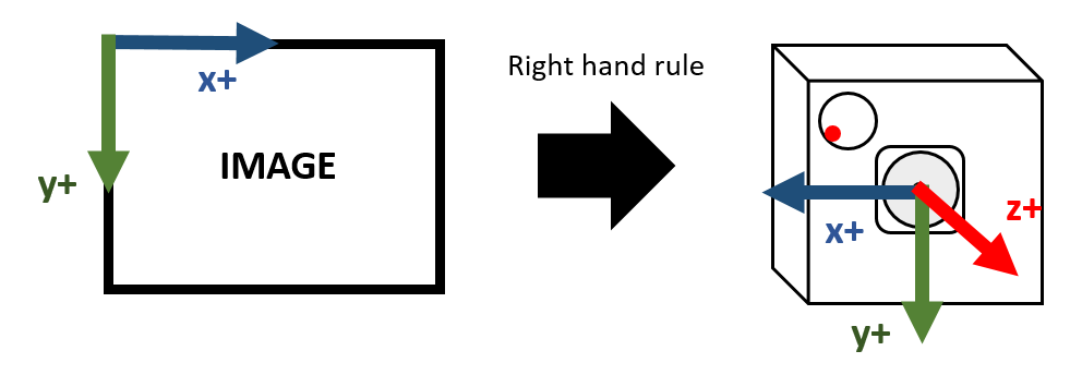
|
The Gyro peripheral coordinate system is as follows (for different models of Gyro, it needs to be confirmed in the corresponding datasheet, using ICM-40607 as follows):
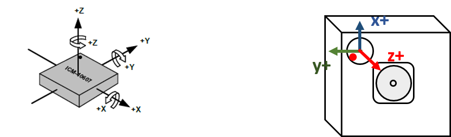
|
The conversion between the two coordinate systems is: Image coordinate system = as32RotationMatrix * Gyro peripheral coordinate system. Based on the above example, the final result of as32RotationMatrix is as follows:
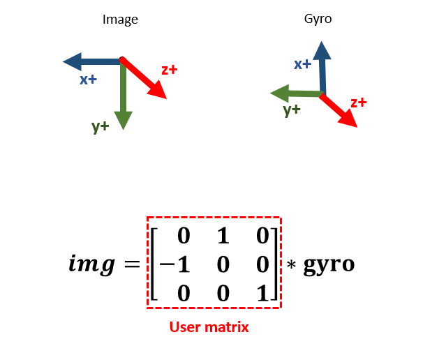
|
3.3.2.2.2 Example
|
|
|
|---|---|
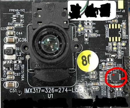
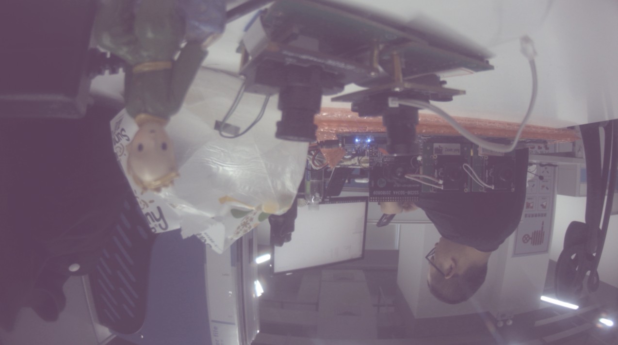
Sensor Front Placement (The gyroscope is located at the red frame position, and the red dot indicates the PIN 1 position of the gyroscope) |
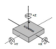
Axis orientation and rotational polarity of gyro sensor ICG-20660 |
|
|
|

|
0, -1, 0, 0, 0, 1] |

|
1, 0, 0, 0, 0, -1] |

|
1, 0, 0, 0, 0, 1] |

|
0, -1, 0, 0, 0, -1] |

|
0, 1, 0, 0, 0, 1] |

|
-1, 0, 0, 0, 0, -1] |

|
-1, 0, 0, 0, 0, 1] |

|
0, 1, 0, 0, 0, -1] |
3.3.2.3 u32UserSliceNum
This input parameter determines how many horizontal slices will be divided by LDC for DIS (MI_LDC_DIS_GYRO) compensation. If the output height (set by MI_LDC_SetOutputPortAttr) is 1512, then each horizontal slice from top to bottom is 1512/6=252. During the setting process, pay attention to whether the slice height is close to the value aligned with 32 to avoid unnecessary CPU resources being occupied. Currently, the recommended setting of this value is 6, and the available setting range is [1, 12].
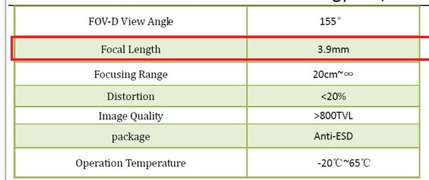
3.3.2.4 u32FocalLengthX and u32FocalLengthY
These two parameters correspond to the setting of focal length in X and Y axis directions. The focal length needs to be converted to pixel units before input. The conversion formula is:
u32FocalLengthX/Y(pixels) = (FocalLength(mm)/CMOS_Unit_CellSize(μm)) * 10^5
FocalLength and CMOS_Unit_CellSize can be found in the Sensor's Lensspec and its datasheet.
|

|
|
|
|
When performing zoom operations, u32FocalLengthX/Y (in pixels) needs to be calculated based on HFOV and VFOV at different focal lengths specified in the lens configuration file. The formula is as follows:
- u32FocalLengthX(pixels) = 100*(0.5*InputImageWidth(pixels))/(tan(HFOV(degree)*PI/180/2)), PI is the ratio of the circumference of a circle to its diameter.
- u32FocalLengthY(pixels) = 100*(0.5*InputImageHeight(pixels))/(tan(VFOV(degree)*PI/180/2)), PI is the ratio of the circumference of a circle to its diameter.
For example, in some lens configuration files, HFOV is referred to as fov_h, and VFOV is referred to as fov_v
|
|
|
|
|
|
|
|
|
|
|
|
|
|
|
|
|
|
|
|
|
- NOTE: When the current ISP module rotates the image by 90 or 270 degrees, the width and height (W/H) of the input to the LDC module will be swapped compared to the pre-rotated image. In this case, FocalLengthX/Y must also be swapped accordingly
3.3.3 Lens parameter configuration
In DIS-GYRO working mode, it is necessary to rely on the nRowTime and nMinFrameLengthLine information of the lens passed in by the previous sensor. Therefore, before running, it is also necessary to confirm whether the configuration parameters of the lens used in the sdk/driver/SensorDriver/directory have been filled in, otherwise it will cause the following errors:
SensorInfo get failed!!! Current: u32ShutterDuration[0], u32RowTime[0], u16TotalLines[0]
In addition to the two parameters mentioned above, if the following parameters exist in the SensorDriver—w_x, h_y, ori_w, ori_h, and binning_mode—they must also be filled in correctly to ensure the accuracy of the anti-shake effect. The instructions for filling in are as follows:
- w_x: The x-coordinate of the cropping starting point relative to the original area (ori_w * ori_h), which must be carefully placed to ensure that the original area is cropped centrally; otherwise, the algorithm will report an error.
- h_y: The y-coordinate of the cropping starting point relative to the original area (ori_w * ori_h), which must be carefully placed to ensure that the original area is cropped centrally; otherwise, the algorithm will report an error.
-
ori_w:
- When binning processing is not applied, this is the width of the sensor's maximum effective resolution (referred to as active full size in some manuals), such as 4032 in the example below.
-
When binning processing is applied, this is the width of the sensor's maximum effective resolution divided by the binning factor. For a 2x2 binning mode setting, the final configuration value would be 4032/2=2016.

-
ori_h:
- When binning processing is not applied, this is the height of the sensor's maximum effective resolution (referred to as active full size in some manuals), such as 3024 in the example below.
-
When binning processing is applied, this is the height of the sensor's maximum effective resolution divided by the binning factor. For a 2x2 binning mode setting, the final configuration value would be 3024/2=1512.
-
binning_mode: Configure according to the corresponding binning mode.
3.3.4 Superimposition of Distortion Calibration
To use this mode, MI_LDC_WORKMODE_DIS_LDC mode should be properly enabled, and the correct lens calibration parameters are required. Please refer to the following document index instructions:
-
To enable MI_LDC_WORKMODE_DIS_LDC mode, there are specific requirements in terms of the calling order of API, please refer to the instruction in MI LDC API;
-
To get the lens calibration parameters, the lens needs to be calibrated first. Please refer to the calibration tool document "SigmaStar_Camera_Calibration_User_Guide", which can be obtained from SourceCode/project/tools/cvtool/doc.
4. DIS-CUST WORKING MODE
4.1 Basic Ideas
The DIS-CUST image stabilization mode is a customized algorithm mode, and the callback function registered by the customer is actually called.
4.2 Basic Principle
The customer needs to register the user-mode callback function through the MI_LDC_SetChnDISAttr interface. When calling this function, the driver will provide the input parameter MI_LDC_IsMatrixInParam_t to the algorithm to help calculate the anti-shake matrix. The calculated anti-shake matrix needs to be filled in by the user into the output parameter MI_LDC_IsMatrixInParam_t . Considering that the matrix calculated by the customer contains floating-point numbers, it needs to be normalized and fixed-pointed according to the following steps.
4.3 TUNING GUIDE
4.3.1 Customized Gyro Driver Adaptation
When using this mode, customers may also need to use the gyro sensor to calculate the anti-shake matrix. For specific porting steps, please refer to Gyro Driver Adaptation of Customized Model.
4.3.2 Parameter settings
4.3.2.1 eMode
DIS algorithm mode.
| Member Name | Description |
|---|---|
| MI_LDC_DIS_CUST | Image stabilization mode based on customized algorithm |
4.3.2.2 pCalIsMatrixCb
Customized callback function.
The type is defined as: typedef MI_S32 (*MI_LDC_CalIsMatrixCb_t)(const MI_LDC_IsMatrixInParam_t * const pstInParam, MI_LDC_IsMatrixOutParam_t * const pstOutParam);
pstInParam is read-only for users and does not need to be filled in. The as32Matrix array in the pstOutParam structure variable needs to be normalized and fixed-pointed. Please refer to the following steps.
4.3.2.3 The process of normalizing and fixing as32Matrix array elements in MI_LDC_IsMatrixOutParam_t
This matrix is a mathematical matrix calculated by the customer, which can be used to complete the plane geometric transformation of the image and generate the output image.
Common types of plane geometric transformations include: translation, rotation, shearing, scaling, and perspective. Each transformation can be superimposed on each other. The superposition process is matrix dot multiplication.

Rigid transformation: translation, rotation
Linear transformation: scaling, shearing, rotation
Affine transformation: linear, rigid
Projection transformation: affine, perspective
4.3.2.3.1 Matrix Usage Instructions
This matrix (m33) describes the mapping relationship from output coordinates to input coordinates. The corresponding relationship between each item in the matrix and the projection transformation is shown below. The values of items in different projection transformations will affect each other, so it is generally necessary to calculate the transformation matrix through tools. Only simple single transformations can be achieved by manual adjustment.

|
The matrix is calculated as follows:
Matrix calculations can be divided into the following types according to requirements. Note that the matrix template provided here is a mapping from the input image to the output image (xy->uv). The result directly calculated based on this template requires its inverse matrix (uv->xy) to be used as the value of m33~origin of the API.
-
Translation matrix template: Translate Δy to the right along the origin (right is positive), and translate Δy downward (downward is positive).

-
Rotation matrix template: Rotate θ degrees counterclockwise around the origin (upper left corner of the input image).

-
Scaling matrix template: Scale the image horizontally by Scalex times and vertically by Scaley times (to achieve mirroring and flipping effects).

-
Shearing matrix template: Tilt the image α degrees along the horizontal axis and β degrees along the vertical axis.

-
The perspective matrix needs to be calculated through the four points of the target plane and their coordinates in the current image.
The use of the m33_origin matrix (uv->xy) requires two steps: quantization and fixed-point conversion. The operations are as follows:
-
Quantification:
m_8 is the quantization factor. After finding the initial M33, each item needs to be divided by m_8 to obtain the quantized M33'.

-
Fixed point:
In order to meet the requirements of the specific algorithm, each m33 needs to be fixed-pointed and uniformly converted into a fixed-point number with the following precision for representation. The fixed-pointing rules are as follows: multiply each item by the corresponding element.

4.3.2.3.2 Single Transformation Example

Input image 800x800 |
|
| Translation Transformation | |
|---|---|
|
Translate right 200 pixels, translate down 100 pixels
Origin m33 (uv->xy): [1,0,-200,0,1,-100,0,0,1] as32Matrix: [16384, 0, -1600, 0, 16384, -800, 0, 0, 1] |
|
| Rotation Transformation | |
|
Rotate 10° counterclockwise around the origin
Origin m33 (uv->xy): [0.984808,-0.173648,0,0.173648,0.984808,0,0,0,1] as32Matrix: [16135, -2845, 0, 2845, 16135, 0, 0, 0, 1] |

|
| Scaling Transformation | |
|
The horizontal axis is reduced to 0.5 of the original value, and the vertical axis is expanded to 1.5 of the original value.
Origin m33 (uv->xy): [2,0,0,0,0.666667,0,0,0,1] as32Matrix: [32768, 0, 0, 0, 10922, 0, 0, 0, 1] |

|
| Shearing Transformation | |
|
Shear in horizontal direction: 15°, shear in vertical direction: 5°
Origin m33 (uv->xy): [1.024005,-0.274381,0,-0.089589,1.024005,0,0,0,1] as32Matrix: [16777, -4495, 0, -1467, 16777, 0, 0, 0, 1] |

|