SDK Architecture Introduction
1. SDK Overview
Alkaid SDK is a software development kit based on the Linux kernel, which includes bootloader, kernel, rootfs and MI multimedia modules. Users can configure and compile a software that can run on the Sgs platform through makefile.
The architecture of Alkaid SDK is shown in the figure below:
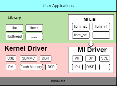
The entire architecture is divided into application layer, software library layer, driver layer and hardware layer from top to bottom.
-
Application layer: Linux applications developed by users, running in Linux user mode;
-
MI user interface layer: The interface of MI SDK in user mode. Applications access MI Driver through this layer to operate hardware.
-
Driver layer: The specific implementation of MI driver;
-
Hardware layer: Hardware of Sgs platform.
2. MI Module Introduction
| Abbr | Full name | Description |
|---|---|---|
| SYS | System | Implements MI system initialization, memory management, and data flow management between various modules |
| SCL | Scaler | Provides functions for scaling, cropping and format conversion, etc. |
| VDISP | Virtual Display | Software stitching |
| DISP | Display Engine | DISP performs hardware stitching for images processed by VDEC/SCL units and encodes them together with AO into HDMI/VGA/CVBS output signal units. |
| VENC | Video Encoder | H.264/H.265/Motion JPEG encoder |
| AI | Audio Input Interface | Audio input capture unit |
| AO | Audio Output Interface | Audio output |
| FB | Frame Buffer | UI display |
| SENSOR | Sensor | Obtains camera interface information, and adjusts resolution, frame rate, etc. |
| VIF | VIDEO Input Interface | MIPI/BT656/BT1120 signal capture unit |
| ISP | Image Signal Processing | Implements HDR, 3D/2D noise reduction, 3A algorithm, WDR and other related functions. |
| RGN | Region | Manages regions, overlays, and masks for SCL data. |
| IVE | Intelligent Video Engine | Provides basic operator support in intelligent graphics recognition algorithms |
| VDF | Video Detection Framework | Middleware framework for integrating various video algorithm recognition libraries, including MD/OD/VG |
| IPU | Intelligence Process Unit | Accelerates the inference of AI models. |
| CIPHER | Cipher | Provides data encryption and decryption functions, including AES, RSA and SHA algorithms. |
The dependencies between modules can be viewed through the lsmod command in the kernel.
mi_venc,mi_scl depend on mi_rgn.
mi_isp depends on mi_vif.
mi_ai,mi_ao depend on mi_aio.
mi_isp,mi_vif depend on mi_sensor.
mi_debug,mi_venc,mi_vdf,mi_ao,mi_ai,mi_ive,mi_scl,mi_rgn,mi_isp,mi_ipu,mi_vif,mi_dummy,mi_sensor depend on mi_sys.
mi_sys,mi_debug,mi_venc,mi_vdf,mi_ao,mi_ai,mi_ive,mi_scl,mi_rgn,mi_isp,mi_ipu,mi_vif,mi_dummy,mi_sensor depend on mi_common.
3. SDK Directory Structure
3.1. SDK Directory Structure Explanation
Please refer to:SDK Directory Structure Explanation
3.2. Decoupling SDK and Kernel
There will inevitably be some coupling between SDK and kernel, which leads to customers needing to rely on Sgs to re release SDK KO when configuring and trimming the kernel themselves;
To achieve this, the SDK section needs to rely on the source code of the kernel source code and open source to the SDK/Linux directory. Users can recompile the SDK KO when configuring and trimming the kernel themselves.
After modifying the kernel, please configure the toolchain environment variables before recompiling the KO:
Complete compilation:
cd project
make clean ;make image -j32
Quick Compilation:
-
Configure the following necessary paths
export PROJ_DIR=/home/xxx/project
export KDIR=/home/xxx/kernel
export SENSOR_DRIVER_DIR=/home/xxx/sdk/driver/SensorDriver/
PROJ_DIR stands for directory after project_xxx.tar.gz decompression.
KDIR stands for directory after kernel_xxx.tar.gz decompression.
SENSOR_DRIVER_DIR stands for sdk/driver/SensorDriver directory after sdk_xxx.tar.gz decompression.
-
Compilation & Packaging
cd sdk/linux make clean ;make all -j32 make install -j32 cd ../../project make image-fast -j32 -
Compile a single mi_xxx.ko
Taking mi_ai.ko as an example:
cd sdk/linux make ai -j32 -
Ignore compilation of certain modules when
make allSet variable FILTER_OUT_MODULES before compilation
If it is not possible or desirable to compile mi_shadow.ko for some reason, you can set:
export FILTER_OUT_MODULES=shadowIf you want to ignore multiple modules, separate them with spaces:
export FILTER_OUT_MODULES=shadow ipu
4. menuconfig Configuration System
menuconfig is a graphical configuration interface that provides comprehensive SDK configuration options. The configuration interface can be started with the make menuconfig command.
4.1. Main Configuration Categories
menuconfig mainly includes the following configuration categories:
- Chip Series Name - Configure the specific chip series model
- Product Form - Select different product forms such as ipc, usbcam, nvr, dispcam
- Development Board - Configure development board model and name related software and hardware settings
- Toolchain Configuration - Set compilation toolchain, architecture and version information
- Uboot Configuration - Configure Uboot build parameters and binary files
- Linux kernel Configuration - Set kernel version and configuration files
- Image Packaging Related Configuration - Configure partition layout, file system and other packaging options
- Sensor Camera Sensor Configuration - Configure IQ files and sensor driver lists
- Customer Function Configuration - Configure MI debug, power management and other functional options
- DRAM_LAYOUT Configuration - Adjust the memory size and layout of various runtime modules
- RTOS Configuration - Configure dual-system and RTOS related options
- SDK Configuration - Configure compilation options for various modules in the SDK
4.2. Configuration Process
- Execute
make menuconfigto start the configuration interface - Select appropriate configuration options according to requirements
- Save the configuration and exit
- Execute
make image -j32to compile
For detailed configuration instructions, please refer to: alkaid_defconfig Configuration Instructions
5. Memory Management
Please refer to:Memory_layout
6. Basic Concepts
-
Data Flow
Each MI Module can be regarded as a data processing unit, where the data flow is uniformly scheduled by MI SYS. The input data flow represents the data received by the unit, and the output data stream represents the data processed by the unit.
-
Control Flow
APP controls the parameters of each MI Module data processing flow, such as configuring MI_VDEC decoding parameters, starting or stopping MI_VDEC channel, setting resolution and format of MI_VDEC channel output port, etc.
-
Channel
For MI modules that need to process or output streams, a channel represents the context of multiplexing a stream for that MI module and related control flow settings.
For modules that support multiplexing like MI_VDEC, MI_DIVP, and MI_DISP, multiple channels can be used.
-
Port
Port is divided into two types, input port and output port. The input port is the location of the channel's input data flow, and the output port is the location of the channel's output data flow.
A channel can have multiple input ports and multiple output ports.
7. root filesystem
Please refer to:partition table
8. bootflow
Please refer to:bootflow