defconfig Configuration Guide
1. About This Document
This document is intended for customers who need to customize their own defconfig on the Comake D3 board. It describes how to use the D3 standard defconfig as a baseline and modify the kernel configuration, the device tree (DTS), and Padmux on a per-module basis (USB, Ethernet, storage, display, audio, UART, and so on).
This document only covers "what needs to be configured, where it is, and how to change it", without going into the underlying principles. For each module it provides: the kernel defconfig items, the DTS nodes (the original text is quoted in full first, followed by the configurable items), and the Padmux items, and it highlights the differences between the linux (Pure Linux) and debian frameworks where relevant.
Configuration information:
- SoC: mhera (D3 is the board/product codename)
- Board: D3 (
project/board/mhera/D3/) - Architecture: ARM64, kernel 6.1
- Storage: eMMC, ext4 filesystem
- Memory: 4096MB (DDR, LPDDR4X)
- Two standard defconfig variants:
linux-(Pure Linux) anddebian-
Configuration hierarchy (a single make defconfig chains together all of the following files):
Project Defconfig
    ├── linux:  project/configs/demo/defconfigs/linux-comake_mhera.emmc.glibc-12.4.0-arm64-ext4.d3.4096.fccsp16_lpddr4x_defconfig
    ├── debian: project/configs/demo/defconfigs/debian-comake_mhera.emmc.glibc-12.4.0-arm64-ext4.d3.4096.fccsp16_lpddr4x_defconfig
    ├── CONFIG_KERNEL_CONFIG      → Kernel Defconfig
    ├── CONFIG_UBOOT_CONFIG       → U-Boot Defconfig
    ├── CONFIG_IMAGE_CONFIG       → partition table config
    ├── CONFIG_SDK_GENERIC_CONFIG → SDK Generic Defconfig
    ├── CONFIG_BOARD="D3"         → project/board/mhera/D3/config/ (board-level JSON)
    └── (screen parameters)        → project/board/mhera/screen_param/config_disp.json
Kernel Defconfig (kernel/arch/arm64/configs/)
    ├── linux:  mhera_comake_d3_linux_emmc_defconfig → CONFIG_SGS_DTB_NAME="mhera-comake-d3-purelinux"
    └── debian: mhera_comake_d3_debian_emmc_defconfig → CONFIG_SGS_DTB_NAME="mhera-comake-d3-debian"
Device Tree (kernel/arch/arm64/boot/dts/sgs/)
    ├── mhera-comake-d3-purelinux.dts   (linux board level)
    ├── mhera-comake-d3-debian.dts      (debian board level)
    ├── mhera.dtsi                      (SoC-level nodes)
    ├── mhera-display-subsystem.dtsi    (display subsystem)
    ├── mhera-comake-d3-padmux.dtsi     (Padmux, shared by linux/debian)
    └── panel-*.dtsi                    (panel parameters)
2. Quick Start (Overall Configuration Flow)
2.1. Starting Point: Deriving Your Own from the Standard defconfig
- Choose a variant: decide whether to use
linux-(Pure Linux) ordebian-(the two use different display frameworks, see Chapter 3). -
Copy and rename: the configuration of a new board is spread across
project/kernel/boot/dts; copy everything from D3 and rename it to your own board name (usingmyboardas an example):# ① project defconfig (project/configs/demo/defconfigs/) cd project/configs/demo/defconfigs cp linux-comake_mhera.emmc.glibc-12.4.0-arm64-ext4.d3.4096.fccsp16_lpddr4x_defconfig \ linux-myboard_mhera.emmc.glibc-12.4.0-arm64-ext4.myboard.4096.fccsp16_lpddr4x_defconfig # ② kernel defconfig (kernel/arch/arm64/configs/) cd kernel/arch/arm64/configs cp mhera_comake_d3_linux_emmc_defconfig mhera_myboard_linux_emmc_defconfig # ③ kernel dts (kernel/arch/arm64/boot/dts/sgs/): board-level dts + padmux cd kernel/arch/arm64/boot/dts/sgs cp mhera-comake-d3-purelinux.dts mhera-myboard-purelinux.dts # use -debian.dts for debian cp mhera-comake-d3-padmux.dtsi mhera-myboard-padmux.dtsi # ④ u-boot (boot/configs/ and boot/arch/arm/dts/) cd boot cp configs/mhera_comake_d3_emmc_arm64_defconfig configs/mhera_myboard_emmc_arm64_defconfig cp arch/arm/dts/mhera-comake-d3.dts arch/arm/dts/mhera-myboard.dts cp arch/arm/dts/mhera-comake-d3-padmux.dtsi arch/arm/dts/mhera-myboard-padmux.dtsi # ⑤ board-level configuration directory (project/board/mhera/) cd project/board/mhera cp -r D3 myboard # contains config_board.json / config_fb.json etc. -
Rename and re-point:
- In ①, change
CONFIG_BOARD="D3"/CONFIG_BOARD_NAME="D3"to your board name, pointCONFIG_KERNEL_CONFIGto the new defconfig in ②, and pointCONFIG_UBOOT_CONFIGto the new defconfig in ④; - In ②, change
CONFIG_SGS_DTB_NAME="mhera-comake-d3-purelinux"to the new dts name in ③ (without the extension); - In the u-boot defconfig of ④, change
CONFIG_DEFAULT_DEVICE_TREE="mhera-comake-d3"to the new dts name.
- In ①, change
-
Change the configuration per module: use the quick reference table below and the main chapters to modify kernel defconfig / DTS / Padmux / board-level JSON.
- Build:
cd project && make linux-myboard_mhera.emmc.glibc-12.4.0-arm64-ext4.myboard.4096.fccsp16_lpddr4x_defconfig && make clean && make image -j16.
2.2. Quick Reference for Common Requirements
| I want to... | See chapter | What to change |
|---|---|---|
| Swap MIPI/HDMI panels, change resolution | Chapter 3 | For panels, see the official screen parameter configuration guide; for DTS/padmux, see Chapter 3 |
| Enable Ethernet (GMAC) | Chapter 4 | Already enabled (SGS_GMAC default y); change DTS phy-mode/max-speed |
| Use USB drive / USB camera / USB serial | Chapter 5 | kernel defconfig (UVC camera is debian-only) |
| Attach a SATA disk | Chapter 6 | Already enabled; only change DTS speed/de-emphasis |
| Use a PCIe device | Chapter 7 | Already enabled; only change lanes/speed |
| Switch eMMC/SD speed mode | Chapter 8 | DTS bus-width / mmc-hs200 etc. |
| Tune UART (baud rate/flow control/mapping) | Chapter 9 | DTS sctp_enable / aliases + padmux |
| Use an SPI device | Chapter 10 | kernel CONFIG_SGS_MSPI + (choose one of SPI_SPIDEV/SGS_SPI_DEVICE) + DTS spidev sub-node |
| Add an I2C sensor | Chapter 11 | DTS speed + i2c sub-node |
| Tune backlight/fan PWM | Chapter 12 | DTS period/duty_cycle + padmux |
| Play audio / record (I2S/DMIC) | Chapter 13 | DTS sound node + padmux |
| Use GPIO for control | Chapter 14 | padmux PINMUX_FOR_GPIO_MODE + pad_init |
| Tune memory layout (MMA/CMA/FB) | Chapter 15 | See Chapter 15 |
3. Display Output (MIPI DSI + HDMI)
Files involved in this chapter:
mhera-comake-d3-purelinux.dts/mhera-comake-d3-debian.dts(board level),mhera-display-subsystem.dtsi,panel-*.dtsi(for panel parameter details, see the official screen parameter configuration guide),mhera-comake-d3-padmux.dtsi,config_disp.json(panel parameters, same external link),config_board.json(panel selection, same external link).
The D3 board display is MIPI DSI 4-lane (RM68200 720×1280) + HDMI (DACOUT_1080P_60); there is no DPI/TTL panel.
3.1. Kernel Configuration
✅ The standard defconfig already includes the display framework; no change is needed.
| Config item | linux | debian | Description |
|---|---|---|---|
CONFIG_FB=y |
✅ | ✅ | framebuffer framework |
CONFIG_DRM=y |
❌ | ✅ | DRM framework (debian) |
CONFIG_SGS_DRM=y |
❌ | ✅ | SGS DRM driver (debian) |
3.2. DTS Configuration
① Board-level DTS (linux: mhera-comake-d3-purelinux.dts)
No special configuration is required for the display part; the touch panel uses the goodix touch IC by default (purelinux uses the FB/mi_disp stack and does not involve the display-subsystem topology):
/* GT911 capacitive touch (I2C1) */
&i2c1 {
    goodix_gt911@5d {
        compatible = "goodix,gt911";
        reg = <0x5D>;
        reset = <PAD_GPIO17>;
        irq = <PAD_GPIO18>;
        // ...
    };
};
Configurable items (linux board-level DTS):
| Item | Meaning | Value |
|---|---|---|
drive-current-level |
panel driving current level | integer |
u8Channel |
MIPI channel selection | 0=Reserved 1=mipi_tx1 2=mipi_tx2 |
eLaneNum |
number of MIPI lanes | integer (4 for D3) |
u8PolCh0~4 |
polarity of each lane | 0/1 |
u8SwapCh0~4 |
swap sequence of each lane | according to the actual panel wiring |
② Board-level DTS (debian: mhera-comake-d3-debian.dts)
On top of the linux version, add the DRM display topology: HDMI→disp0, MIPI→disp1, and delete unused endpoints with /delete-node/ (DRM requires one-to-one connections):
/ {
    /* ... */

    display-subsystem {
        panels {
            panel_misc {
                drive-current-level = <1>;          // configurable
                mipi-lane-config {
                    u8Channel = <1>;                    // configurable
                    eLaneNum = <4>;                     // configurable
                    u8PolCh0 = <0>;                     // configurable
                    u8PolCh1 = <0>;                     // configurable
                    u8PolCh2 = <0>;                     // configurable
                    u8PolCh3 = <0>;                     // configurable
                    u8PolCh4 = <0>;                     // configurable
                    u8SwapCh0 = <2>;                    // configurable
                    u8SwapCh1 = <0>;                    // configurable
                    u8SwapCh2 = <1>;                    // configurable
                    u8SwapCh3 = <3>;                    // configurable
                    u8SwapCh4 = <4>;                    // configurable
                };
            };
        };
    };
};

/* DPI: not used on D3 */
&disp0 {
    port {
        /delete-node/ endpoint@0; /* disp0_out_dpi */
    };
};

&disp1 {
    port {
        /delete-node/ endpoint@0; /* disp1_out_dpi */
    };
};

&dpi_dev {
    ports {
        /delete-node/ port@0; /* disconnect dpi_in_disp0/dpi_in_disp1 */
    };
};

/* MIPI: only disp1 drives the MIPI panel — disconnect disp0 */
&disp0 {
    port {
        /delete-node/ endpoint@1; /* disp0_out_mipi */
    };
};

&{/display-subsystem/drm-device/mipi_dsi} {
    ports {
        port@0 {
            /delete-node/ endpoint@0; /* mipi_in_disp0 */
        };
    };
};

/* HDMI: only disp0 drives HDMI output — disconnect disp1 */
&disp1 {
    port {
        /delete-node/ endpoint@2; /* disp1_out_hdmi */
    };
};

&{/display-subsystem/drm-device/hdmi} {
    ports {
        port@0 {
            /delete-node/ endpoint@1; /* hdmi_in_disp1 */
        };
    };
};
Configurable items (debian board-level DTS additions):
| Item | Meaning | Value |
|---|---|---|
/delete-node/ disconnection |
delete the DPI channel | D3 has no DPI panel, keep it deleted |
| debian disp↔channel pairing | HDMI is fixed to disp0, MIPI is fixed to disp1 | add/remove the corresponding endpoints when changing the topology |
③ Display subsystem (mhera-display-subsystem.dtsi): debian (DRM) only; purelinux does not use the DRM stack at all, and the DRM-related parts of this file have no effect:
/ {
    display-subsystem {
        compatible = "sgs,display-subsystem","simple-mfd";

        drm-device {
            compatible = "sgs,drm","simple-mfd";   // debian only

            disp0: port@0 {
                dev-id = <0>;
                preferred = <1>;              // configurable
                mop-layers = <4 0 32                // configurable (layer configuration)
                              3 0 1
                              3 1 1>;
                port {
                    disp0_out_dpi: endpoint@0 { remote-endpoint = <&dpi_in_disp0>; };    // configurable (change when swapping panels)
                    disp0_out_mipi: endpoint@1 { remote-endpoint = <&mipi_in_disp0>; };   // configurable (change when swapping panels)
                    disp0_out_hdmi: endpoint@2 { remote-endpoint = <&hdmi_in_disp0>; };   // configurable (change when swapping panels)
                };
            };

            /* ... */
            dpi_dev: dpi {
                compatible = "sgs,dpi";
                status = "okay";      // configurable
                /* ... */
            };

            mipi_dsi {
                compatible = "sgs,mipi-dsi";
                status = "okay";   // configurable
                /* ... */
            };

            hdmi {
                compatible = "sgs,hdmi";
                status = "okay";     // configurable
                /* ... */
            };
        };

        drmscl { rdma-support = <0>; rot-support = <1>; rdmaid = <1>; sclid = <0x2>; };

        panels: panels {
            compatible = "simple-mfd";
            backlight_dev1: backlight_dev1 { };
            panel_misc: panel_misc { };
            panel_misc_edp: panel_misc_edp { };
        };

        bridges: bridges { };
    };
};

#include "panel-SAT070AT50H18BH.dtsi"
#include "panel-RM68200HDH40145.dtsi"
Configurable items (debian only):
| Item | Meaning | Value |
|---|---|---|
mop-layers of disp0/disp1 |
layer configuration | <layerType subType winCount ...> |
status of dpi/mipi_dsi/hdmi |
channel enable | "okay" / "disabled" |
remote-endpoint of each endpoint |
which channel the panel is connected to | change when swapping panels |
backlight_dev1 under panels |
backlight control | works with PWM |
The rest (
compatible,reg,dev-id, and all#*-cells) are fixed values; do not modify.
3.3. Padmux Configuration (mhera-comake-d3-padmux.dtsi)
MIPI DSI 4-lane + I2C1 (#if 1):
<PAD_OUTP_TX0_CH0  PINMUX_FOR_MIPITX_OUT_MODE_1  MDRV_PUSE_TX_MIPI_P_CH0>,
<PAD_OUTN_TX0_CH0  PINMUX_FOR_MIPITX_OUT_MODE_1  MDRV_PUSE_TX_MIPI_N_CH0>,
/* CH1~CH4 follow the same pattern, 4 lanes in total */
<PAD_I2C1_SCL      PINMUX_FOR_I2C1_MODE_1        MDRV_PUSE_I2C1_SCL>,
<PAD_I2C1_SDA      PINMUX_FOR_I2C1_MODE_1        MDRV_PUSE_I2C1_SDA>,
HDMI TX (#if 1):
<PAD_HDMITX_HPD  PINMUX_FOR_GPIO_MODE    MDRV_PUSE_HDMI_HOT_PLUG>,
<PAD_HDMITX_SCL  PINMUX_FOR_I2C0_MODE_1  MDRV_PUSE_HDMI_RX_SCL>,
<PAD_HDMITX_SDA  PINMUX_FOR_I2C0_MODE_1  MDRV_PUSE_HDMI_RX_SDA>,
Corresponding schematic:
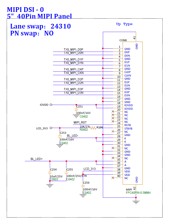
Figure 3-1 MIPI DSI Padmux schematic
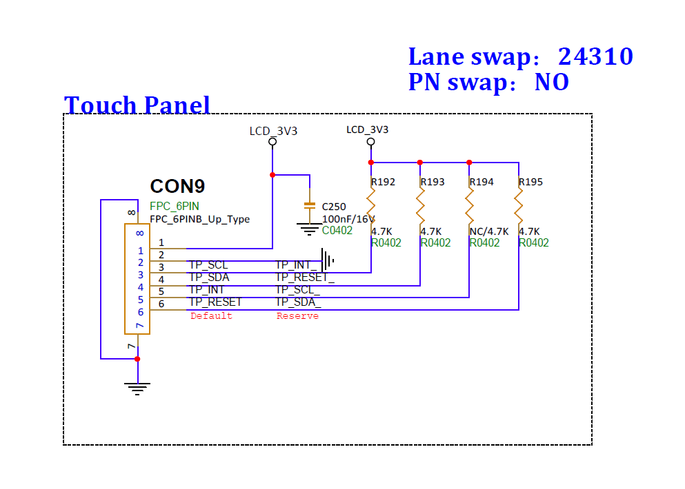
Figure 3-2 HDMI Padmux schematic
3.4. Screen Parameter Configuration
The detailed configuration of screen parameters (panel timings, config_disp.json, panel selection in config_board.json, etc.) is outside the scope of this document. Please refer to the official documentation:
Comake Screen Parameter Configuration Guide
3.5. Verification Commands
ls /dev/fb*                          # Expected: fb0/fb1 are visible (linux)
ls /sys/class/drm/                   # Expected: card0 etc. are visible (debian)
cat /proc/mi_modules/mi_disp/mi_disp0   # Expected: panel parameters are read back (linux)
3.6. Related Links
- For display configuration under linux, refer to MI DISP API;
- For screen parameter configuration, refer to Screen Parameter Usage Guide.
4. Ethernet (GMAC0 / GMAC1)
Files involved in this chapter:
mhera_comake_d3_linux_emmc_defconfig/mhera_comake_d3_debian_emmc_defconfig,mhera.dtsi(gmac0/gmac1),mhera-comake-d3-padmux.dtsi(RGMII/RMII blocks).
D3 supports dual gigabit GMAC (GMAC0/1, RGMII to Gphy / RMII to Ephy).
4.1. Kernel Configuration
✅ GMAC is already enabled in the standard defconfig:
CONFIG_SGS_GMACisdefault yin the kernel Kconfig and automaticallyselect STMMAC_ETH, so no manual addition is needed. (debian/linux difference: none)
If you need explicit control (or want to build it as the sgs_gmac.ko module), you can write it explicitly:
CONFIG_SGS_GMAC=y          # SGS GMAC driver (default y)
CONFIG_STMMAC_ETH=y        # automatically selected by SGS_GMAC
4.2. DTS Configuration (mhera.dtsi)
Node example (fixed items omitted):
#if IS_ENABLED(CONFIG_SGS_GMAC)
        gmac0: gmac0 {
            compatible = "sgs,gmac","snps,dwmac-5.10a";
            // ...
            reset-io = /bits/ 8 <PAD_RGMII0_RSTN>;   // configurable: PHY reset pin
            mclk = /bits/ 8 <25>;                    // configurable: 0 off / 25:25MHz / 50:50MHz
            disable-txfc = /bits/ 8 <1>;             // configurable: 1 disable flow control / 0 enable
            snps,tso;                                // configurable: commenting out this line disables TSO
            phy-mode = "rgmii";                       // configurable: rgmii / rmii
            max-speed = <1000>;                       // configurable: 10 / 100 / 1000
            status = "ok";                            // configurable

            /* ... */
        };
        /* gmac1 has the same structure: reg=0x1F34B400, reset-io=<PAD_RGMII1_RSTN>, phy-handle=<&phy1> */
#endif
Configurable items:
| Item | Meaning | Value |
|---|---|---|
phy-mode |
PHY interface | "rgmii" / "rmii" |
max-speed |
maximum speed | 10 / 100 / 1000 |
mclk |
whether to output a clock to the PHY | 0=off 25=25MHz 50=50MHz |
reset-io |
PHY reset pin | PAD_RGMII0_RSTN etc. |
disable-txfc |
disable hardware flow control | 1=disable 0=enable |
snps,tso |
enable TSO | commenting out this line disables it |
status |
enable | "ok" / "disabled" |
4.3. Padmux Configuration
RGMII of GMAC0/1 is #if 1 and RMII is #if 0 (choose one; switch them when changing the interface):
- RGMII (default):
PAD_RGMII0_RSTN(GPIO),PAD_RGMII0_MCLK/RXCLK/RXCTL/RXD0~3/TXCLK/TXCTL/TXD0~3/MDIO/MDC, with PUSE asMDRV_PUSE_ETH0_*; - RMII (alternative):
PAD_RGMII0_RXCLK/RXCTL/RXD0~1/TXCTL/TXD0~1/MDIO/MDCusePINMUX_FOR_RMII0_MODE_1.
Corresponding schematic:
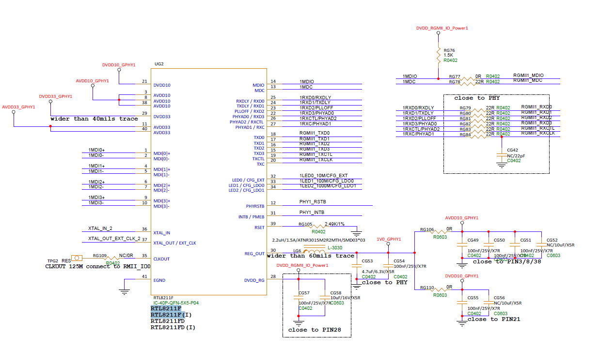
Figure 4-1 GMAC Padmux schematic
4.4. Verification Commands
4.5. Related Links
5. USB
Files involved in this chapter:
mhera_comake_d3_linux_emmc_defconfig/mhera_comake_d3_debian_emmc_defconfig,mhera.dtsi(ehci/dwc3),mhera-comake-d3-padmux.dtsi(VBUS detection).
mhera supports 4 USB ports: 2 USB2.0 host-only ports and 2 USB3.0 ports (Port2/Port3, host/device capable). The standard D3 defconfig already enables them.
5.1. Kernel Configuration
✅ The standard defconfig already includes them; no change is needed. (debian extra: USB serial and UVC camera, see the notes below)
CONFIG_USB=y
CONFIG_USB_XHCI_HCD=m              # USB3.0 host (xhci-hcd.ko)
CONFIG_USB_EHCI_HCD=m              # USB2.0 host (ehci-hcd.ko)
CONFIG_USB_STORAGE=m               # USB drive
CONFIG_SGS_USB_DWC3_OF_SIMPLE=m    # DWC3 glue (sgs-dwc3-of-simple.ko)
CONFIG_SGS_USB3_PHY=m              # USB3 PHY (sgs-usb3-phy.ko)
CONFIG_SGS_USB2_PHY=m              # USB2 PHY (sgs-usb2-phy.ko)
- linux extra:
CONFIG_USB_SERIAL=y(USB serial),CONFIG_USB_NET_RNDIS_HOST=y. - debian extra:
CONFIG_USB_SERIAL=m(CH341/CP210X),CONFIG_USB_VIDEO_CLASS=m(UVC camera). - For USB Device (gadget): add
CONFIG_USB_GADGET=m+ the corresponding function (configfs/adb/UVC). The D3 standard configuration currently focuses on host mode.
5.2. DTS Configuration (mhera.dtsi)
① USB2.0 host (Port0/Port1): node example (fixed items omitted):
sgs_u2phy1: sgs-usb2-phy1 {
    compatible = "sgs,u2phy";
    // ...
    status = "okay";
};

sgs-ehci-1 {
    compatible = "sgs,ehci";
    // ...
    phys = <&sgs_u2phy1>;
    phy-names = "usb";
    status = "ok";   // configurable
};
/* sgs_u2phy2 + sgs-ehci-2 (Port1) have the same structure: reg=0x1f286400, port_id=<1> */
Configurable item: status ("ok"/"disabled"). The rest (compatible/reg/clocks/interrupts/phys) are fixed values.
② USB3.0 (Port3, standalone PIPE PHY): node example (fixed items omitted):
u3phy_p3_utmi: utmi@1f286e00 {
    compatible = "sgs,generic-utmi";
    // ...
    status = "okay";
};

u3phy_p3_pipe: pipe@1f2a5200 {
    compatible = "sgs,generic-pipe";
    // ...
    status = "okay";
};

/* ... */
usb3drd_p3: usb3-p3 {
    compatible = "sgs,generic-dwc3";
    // ...
    usb-phy = <&u3phy_p3_utmi>;
    status = "okay";

    dwc3_p3: dwc3 {
        dr_mode = "host";                 // configurable: host / peripheral
        compatible = "snps,dwc3";
        // ...
        maximum-speed = "super-speed";    // configurable: super-speed / high-speed
        phys = <&u3phy_p3_utmi>, <&u3phy_p3_pipe>;   // configurable: change according to the actual PHYs
        phy-names = "usb2-phy", "usb3-phy";          // configurable: match `phys`
        // ...
        status = "okay";                  // configurable
    };
};
Configurable items:
| Item | Meaning | Value |
|---|---|---|
dwc3.dr_mode |
mode | "host" host / "peripheral" device |
dwc3.maximum-speed |
maximum speed | "super-speed"/"high-speed" |
dwc3.phys / phy-names |
PHY references | change according to the PHYs actually used |
usb3drd_p3.status / dwc3.status |
enable | "okay"/"disabled" |
Port2 shares the same PHY (SUPPHY lane1) with PCIE0; the default is "PCIE0 2x + Port2 USB2.0 only". To make Port2 run USB3.0, give SUPPHY to Port2 (disable PCIE0 or downgrade it to 1x) and change the status and
physreferences ofu3phy_p2_pipe/usb3drd_p2(the nodesu3phy_p2_utmi/u3phy_p2_pipe/usb3drd_p2have the same structure as Port3). The remainingcompatible/reg/clocks/interrupts/snps,*quirk etc. are fixed values; do not modify.
5.3. Padmux Configuration
/* USB VBUS detection */
<PAD_SAR_GPIO3  PINMUX_FOR_VBUS0_DET_MODE_1  MDRV_PUSE_USB3_VBUS_DETECT>,
<PAD_SAR_GPIO4  PINMUX_FOR_VBUS1_DET_MODE_1  MDRV_PUSE_USB2_VBUS_DETECT>,
Corresponding schematic:
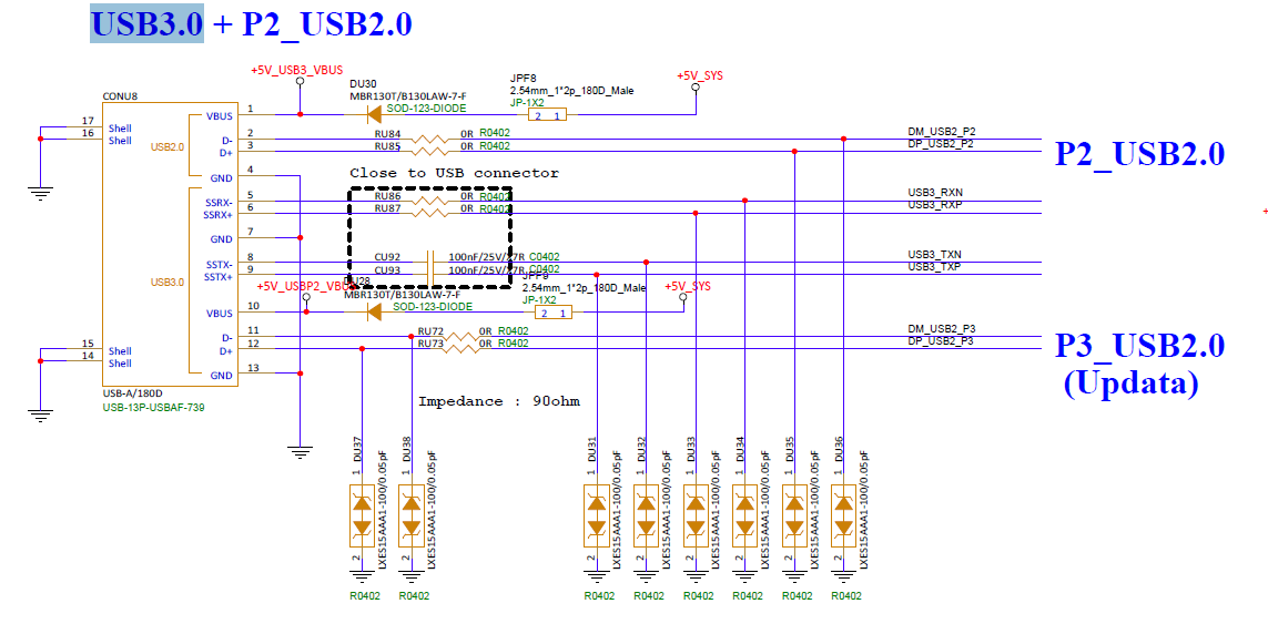
Figure 5-1 USB Padmux schematic
5.4. Verification Commands
lsusb             # Expected: USB devices are listed
ls /dev/sd*        # Expected: sda/sdb appear if a USB drive is inserted
5.5. USB VBUS Configuration
The VBUS power supply of USB ports is controlled automatically by the USB driver; no application-level intervention or extra DTS property is needed: when the host controller is initialized, the driver looks up the VBUS supply GPIO of the port in the padmux table and pulls it high to power on, and pulls it low to power off when the controller is removed or suspended.
Therefore, in the pin list of mhera-comake-d3-padmux.dtsi, you only need to add one line for each port whose VBUS needs to be controlled (GPIO mode is mandatory):
PAD_xxx: the pad connected to the VBUS enable pin of the USB port on the hardware (check the schematic).MDRV_PUSE_USBx_VBUS: replacexwith the USB port number (0/½/3).- The VBUS detection pin (
MDRV_PUSE_USBx_VBUS_DETECT) is different from the supply pin; detection is already configured in Section 5.3.
D3 status:
mhera-comake-d3-padmux.dtsicurrently has only VBUS detection (see Section 5.3) and no VBUS supply design. If a port needs driver-controlled VBUS, add one line as in the example above. Notes:
- The driver is active-high by default (pull high = power on); if the hardware is active-low, the driver must be modified — there is no polarity switch in the DTS layer.
- The pin must be written as
PINMUX_FOR_GPIO_MODE, otherwise the driver will not take over. - padmux is a static boot-time configuration; the table is looked up automatically at probe time, and no other operation is needed after it is configured. Do not let one pad be occupied by multiple pin uses.
5.6. Related Links
6. SATA
Files involved in this chapter:
mhera_comake_d3_linux_emmc_defconfig/mhera_comake_d3_debian_emmc_defconfig,mhera.dtsi(sataphy/sata).
D3 supports two SATA ports (for HDD/SSD). The standard defconfig already enables them.
6.1. Kernel Configuration
✅ The standard defconfig already includes them; no change is needed. (debian/linux difference: none)
CONFIG_SATA_AHCI_PLATFORM=y    # AHCI platform driver
CONFIG_SGS_SATA_HOST=y         # SGS SATA host controller
6.2. DTS Configuration (mhera.dtsi)
Node example (fixed items omitted):
sgs_sataphy: sgs-sata-phy {
    compatible = "sgs,sataphy";
    // ...
    phy_mode = <2>;                            // configurable: 0=GEN1 1=GEN2 2=GEN3
    tx_ssc_mode = <0>;                         // configurable: 0=off 1=on
    tx_gen1_gen2_Vpp = <0xFF>,<0xFF>;          // configurable: 0xFF=default
    tx_gen3_de_emphasis = <0xFF>,<0xFF>,<0xFF>;// configurable: 0xFF=default
    rx_eq_rs1 = <0xFF>,<0xFF>,<0xFF>;          // configurable: 0xFF=default
    rx_eq_rs2 = <0xFF>,<0xFF>,<0xFF>;          // configurable: 0xFF=default
    rx_eq_ctle = <0xFF>;                       // configurable: 0xFF=default
    status = "ok";                          // configurable
};

sata {
    compatible = "sgs,sata";
    // ...
    phys = <&sgs_sataphy>;
    fbs_mode;                 // configurable (add to enable)
    //sata_acp;               // configurable (add to enable)
    //dma-coherent;           // configurable (add to enable)
};
/* sgs_sata1phy + sata1 (Port1) have the same structure, reg uses 0x1F288* / 0x1F346A00 */
Configurable items:
| Item | Meaning | Value |
|---|---|---|
phy_mode |
PHY speed | 0=GEN1 1=GEN2 2=GEN3 |
tx_ssc_mode |
spread-spectrum clock | 0=off 1=on |
tx_gen1_gen2_Vpp |
GEN1/GEN2 voltage swing | 0xFF=default |
tx_gen3_de_emphasis |
GEN3 de-emphasis | <enable>,<db>,<level>, 0xFF=default |
rx_eq_rs1/rs2/ctle |
receiver equalization parameters | 0xFF=default |
fbs_mode |
FIS-Based Switching | add to enable |
sata_acp / dma-coherent |
ACP / DMA coherency | add to enable |
status |
enable | "ok" / "disabled" |
compatible/reg/reg-names/interrupts/clocks/physare fixed values; do not modify.
6.3. Padmux
SATA needs no extra padmux (its GPIO is multiplexed with DMIC, see the Audio chapter).
Corresponding schematic:
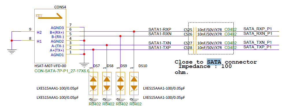
Figure 6-1 SATA schematic
6.4. Verification Commands
6.5. Related Links
7. PCIe
Files involved in this chapter:
mhera_comake_d3_linux_emmc_defconfig/mhera_comake_d3_debian_emmc_defconfig,mhera.dtsi(pcie0/pcie1),mhera-comake-d3-padmux.dtsi(PCIE1_PERST).
D3 supports PCIe RC/EP/hot-plug. The standard defconfig already enables them.
7.1. Kernel Configuration
✅ The standard defconfig already includes them; no change is needed. (debian/linux difference: none)
7.2. DTS Configuration (mhera.dtsi)
Node example (pcie0 as an example, fixed items omitted):
pcie0: pcie@1F356000 {
    compatible = "sgs,dw-pcie-earlyparam"; /* [rc]"sgs,dw-pcie" [ep]"sgs,dw-pcie-ep" */
    // ...
    device_type = "pci";
    bus-range = <0x00 0xff>;        // configurable: bus number range

    /* ... */

    linux,pci-domain = <0>;
    num-lanes = <2>;                // configurable: 1 / 2
    max-link-speed = <2>;           // configurable: 1=Gen1 2=Gen2
    // ...
    dma_read_channel_number = <8>;  // configurable: number of DMA read channels
    dma_write_channel_number = <8>; // configurable: number of DMA write channels
    clk_source = <0>;               // configurable: 0=internal 1=internal_2 2=external 3=wire
    //ssc_enable;
    status = "okay";            // configurable
};
/* pcie1 has the same structure: portid=<1>, reg 0x1f35a000, linux,pci-domain=<1> */
Configurable items:
| Item | Meaning | Value |
|---|---|---|
num-lanes |
link width | 1 / 2 |
max-link-speed |
maximum link speed | 1=Gen1 2=Gen2 |
clk_source |
clock source selection | 0=internal 1=internal_2 2=external 3=wire |
bus-range / ranges |
bus number/address mapping | according to the actual configuration |
dma_read/write_channel_number |
number of DMA channels | 8 by default |
status |
enable | "okay" / "disabled" |
Note: PCIE0 shares SUPPHY with USB Port2 (see the USB chapter); to make Port2 run USB3.0, disable PCIE0 here or downgrade it to 1x. On the D3 board, I2C2 controls PCIE0 and I2C4 controls PCIE1 (see the I2C chapter).
7.3. Verification Commands
7.4. Related Links
8. eMMC / SD Card
Files involved in this chapter:
mhera_comake_d3_linux_emmc_defconfig/mhera_comake_d3_debian_emmc_defconfig,mhera.dtsi(sgs_sdmmc0/1),mhera-comake-d3-padmux.dtsi(eMMC/SD0 blocks).
The standard defconfig already enables them (eMMC as the system disk, SD card as extended storage).
8.1. Kernel Configuration
✅ The standard defconfig already includes them; no change is needed. (debian/linux difference: none)
8.2. DTS Configuration (mhera.dtsi)
Node example (fixed items omitted):
#if IS_ENABLED(CONFIG_SGS_SDMMC)
        // emmc
        sgs_sdmmc0: sgs_sdmmc0 {
            compatible = "sgs,sdmmc";
            bus-width = <8>;                    // configurable: 8 / 4 / 1
            max-frequency = <200000000>;        // configurable: Hz
            non-removable;
            //broken-cd;
            cap-mmc-highspeed;
            mmc-hs200-1_8v;
            mmc-hs400-1_8v;
            //mmc-hs600-1_8v;
            no-sdio;
            no-sd;
            // ...
            clk-driving = <0xffffffff>;         // configurable: 0xffffffff=default
            cmd-driving = <0xffffffff>;         // configurable: 0xffffffff=default
            data-driving = <0xffffffff>;         // configurable: 0xffffffff=default
            en-clk-phase = /bits/ 8 <0>;        // configurable: phase tuning
            rx-clk-phase = <0>;                 // configurable: 0~3
            tx-clk-phase = <0>;                 // configurable: 0~3
            status = "ok";
        };

        // sd
        sgs_sdmmc1: sgs_sdmmc1 {
            compatible = "sgs,sdmmc";
            bus-width = <4>;                    // configurable: 4 / 1
            max-frequency = <200000000>;        // configurable: Hz
            cap-sd-highspeed;                    // configurable (add to enable)
            sd-uhs-sdr104;                     // configurable (add to enable)
            cap-sdio-irq;                        // configurable (add to enable)
            no-mmc;
            // ...
            pwr-pad = <PAD_SD0_GPIO0>;          // configurable: power pin
            cdz-pad = <PAD_SD0_CDZ>;            // configurable: card detect pin
            pwr-on-delay = <1>;                 // configurable: ms
            pwr-off-delay = <30>;               // configurable: ms
            clk-driving = <1>;                  // configurable
            cmd-driving = <1>;                  // configurable
            data-driving = <1>;                // configurable
            en-clk-phase = /bits/ 8 <0>;        // configurable: phase tuning
            rx-clk-phase = <0>;                 // configurable: 0~3
            tx-clk-phase = <0>;                 // configurable: 0~3
            status = "ok";
        };
#endif
Configurable items:
| Item | Meaning | Value |
|---|---|---|
bus-width |
bus width | eMMC 8 / SD 4 (or 1) |
max-frequency |
maximum clock | value (Hz) |
cap-mmc-highspeed / cap-sd-highspeed |
high-speed mode | add to enable |
mmc-hs200-1_8v / mmc-hs400-1_8v / mmc-hs600-1_8v |
eMMC high-speed mode | add to enable (corresponding CONFIG required) |
sd-uhs-sdr50 / sd-uhs-sdr104 / sd-uhs-ddr50 |
SD UHS speed | add to enable |
non-removable / broken-cd |
non-removable / no card detect | add to enable |
no-sd / no-sdio / no-mmc |
disable protocol | choose according to the card type |
cap-sdio-irq |
SDIO interrupt mode | add to enable |
pwr-pad / cdz-pad |
power/card detect pin | <PAD_xxx> |
fake-cdz / rev-cdz |
card detect method | 0/1 |
pwr-on-delay / pwr-off-delay |
power on/off delay | ms |
sdio-use-1bit |
SDIO uses 1 bit | 0/1 |
clk-driving / cmd-driving / data-driving |
driving strength of each signal | level, 0xffffffff=default |
en-clk-phase / rx-clk-phase / tx-clk-phase |
four-phase tuning | 0/1 and 0~3 |
en-eight-phase / rx-eight-phase / tx-eight-phase |
eight-phase tuning | 0/1 |
status |
enable | "ok" / "disabled" |
8.3. Padmux Configuration
- eMMC (8bit):
PAD_EMMC_D0~D7/PAD_EMMC_CLK/PAD_EMMC_CMD/PAD_EMMC_DS/PAD_EMMC_RSTN, usePINMUX_FOR_EMMC_8B_MODE_1. - SD card:
PAD_SD0_D0~D3/PAD_SD0_CLK/PAD_SD0_CMDusePINMUX_FOR_SD0_MODE_1,PAD_SD0_GPIO0(power, GPIO mode),PAD_SD0_CDZ(card detect,PINMUX_FOR_SD0_CDZ_MODE_1).
Corresponding schematic:
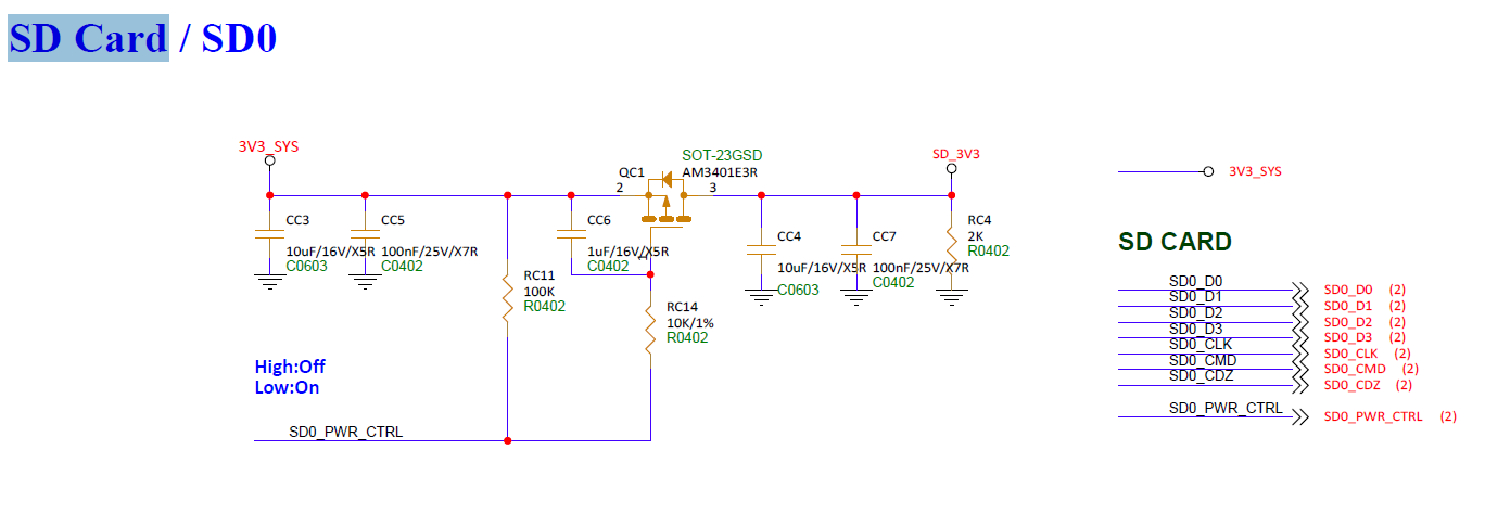
Figure 8-1 eMMC / SD card schematic
8.4. Verification Commands
8.5. Related Links
9. UART
Files involved in this chapter:
mhera_comake_d3_linux_emmc_defconfig/mhera_comake_d3_debian_emmc_defconfig,mhera.dtsi(fuart/uart0~3 + aliases),mhera-comake-d3-padmux.dtsi(FUART/UART½/3 blocks).
The console is uart0 (console=ttyS0); there are also FUART (4-wire, hardware flow control, ttyS2) and UART½/3. The standard defconfig already enables them.
9.1. Kernel Configuration
✅ The standard defconfig already includes them; no change is needed. (debian/linux difference: none)
9.2. DTS Configuration (mhera.dtsi)
Node example (fuart + uart0 as examples; the rest have the same structure, fixed items omitted):
fuart: fuart@1F220400 {
    compatible = "sgs,uart";
    // ...
    sctp_enable = <0>;        // configurable: hardware CTS/RTS flow control (FUART only)
    digmux = <1>;             // fixed (must not be duplicated across uarts)
    rx_fifo_level = <0>;      // configurable: 0~3
    tx_fifo_level = <0>;      // configurable: 0~3
    status = "okay";         // configurable
};

uart0: uart0@1F221000 {
    compatible = "sgs,uart";
    // ...
    digmux = <0>;             // fixed (must not be duplicated across uarts)
    dma-enable;               // configurable (add to enable)
    rx_fifo_level = <0>;      // configurable: 0~3
    tx_fifo_level = <0>;      // configurable: 0~3
    status = "okay";         // configurable
};
/* uart1/uart2/uart3 have the same structure, reg is 0x1F221200/0x1F221400/0x1F221600 respectively */
Aliases (determine the /dev/ttySN mapping):
aliases {
    console = &uart0;   /* console = /dev/ttyS0 */
    serial0 = &uart0;
    serial1 = &uart1;   /* ttyS1 */
    serial2 = &fuart;   /* ttyS2 */
    serial3 = &uart2;   /* ttyS3 */
    serial4 = &uart3;   /* ttyS4 */
};
Configurable items:
| Item | Meaning | Value |
|---|---|---|
dma-enable |
enable DMA mode | add to enable |
sctp_enable |
hardware CTS/RTS flow control (FUART only) | 1=on 0=off |
rx_fifo_level |
RX interrupt watermark | 0=1 char 1=¼ full 2=½ full 3=2 from full |
tx_fifo_level |
TX interrupt watermark | 0=empty 1=2 chars 2=¼ full 3=½ full |
status |
enable | "okay" / "disabled" |
digmux(must not be duplicated across uarts),compatible/reg/interrupts/clocksare fixed values; do not modify.
9.3. Padmux Configuration
- FUART (4-wire) (
#if 1):PAD_FUART_TX/RX/RTS/CTSusePINMUX_FOR_FUART_MODE_1. - UART1 (golden finger,
#if 1):PAD_UART1_TX/RXusePINMUX_FOR_UART1_MODE_1. - UART2 (golden finger,
#if 1):PAD_UART2_TX/RXusePINMUX_FOR_UART2_MODE_1. - UART3 (reuses HSYNC/VSYNC pins,
#if 1):PAD_HSYNC/PAD_VSYNCusePINMUX_FOR_UART3_MODE_4.
Corresponding schematic:
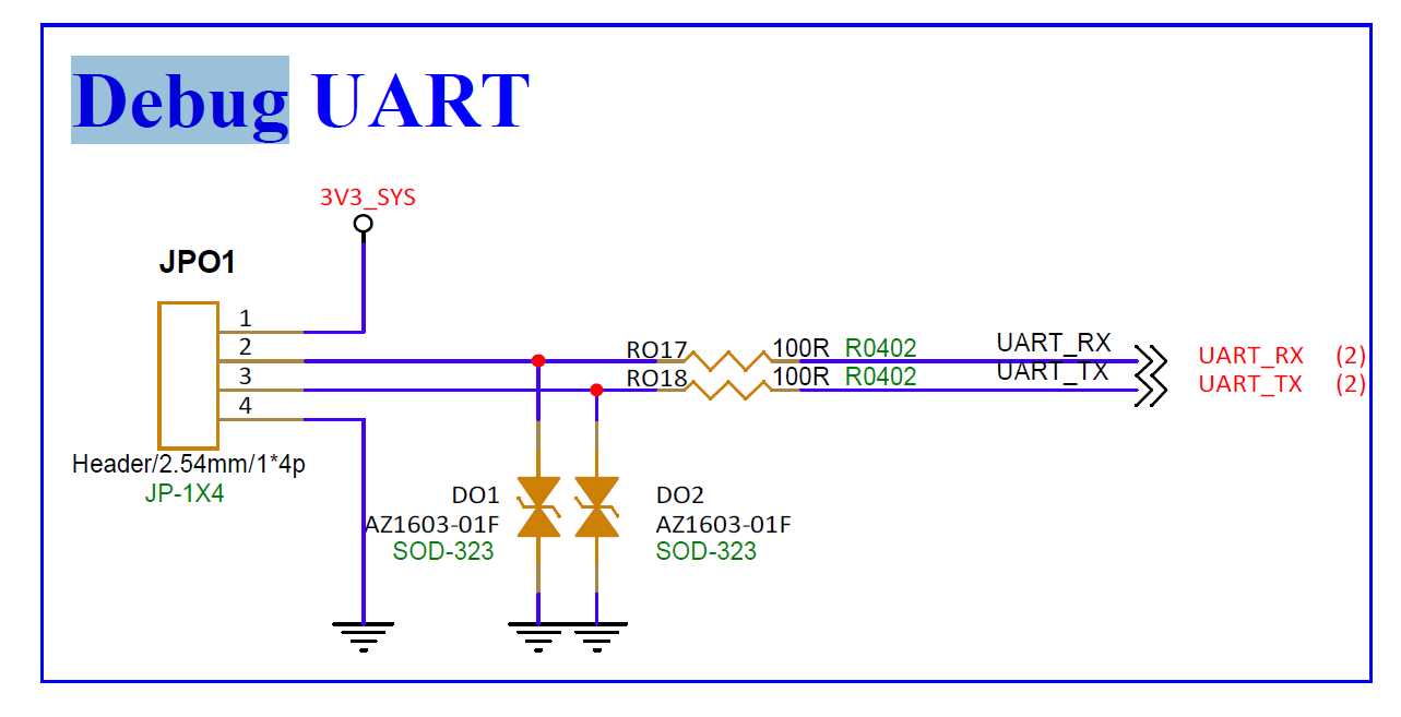
Figure 9-1 UART Padmux schematic
9.4. Verification Commands
9.5. RS232/485 Configuration
RS485 and RS232 both reuse the UART hardware channel; under Linux they uniformly use the standard /dev/ttyS* nodes. The configuration differences between the two:
| Item | RS485 (half-duplex, multi-slave bus) | RS232 (full-duplex, point-to-point) |
|---|---|---|
| Direction control | requires one GPIO to switch the external transceiver direction, done automatically by the kernel RS485 framework (serial_rs485 + TIOCSRS485 ioctl) |
none |
| Extra DTS configuration | requires rs485-gpios |
none |
| Extra application steps | enable kernel RS485 mode via TIOCGRS485/TIOCSRS485 at initialization |
none |
- RS232: configure Section 9.2 (nodes + aliases) and Section 9.3 (TX/RX two-wire padmux); no extra configuration.
-
RS485: on top of Sections 9.2/9.3, two more steps are needed:
-
Enable the gpio-controller binding of the gpio node (not declared by default; must be enabled before
rs485-gpioscan reference a GPIO):&gpio { gpio-controller; #gpio-cells = <2>; }; -
Add the direction-control GPIO to the corresponding uart node (the third parameter is the polarity:
1=GPIO_ACTIVE_LOWtransmit on low,0=GPIO_ACTIVE_HIGHtransmit on high):&uart1 { rs485-gpios = <&gpio 43 1>; /* GPIO_ACTIVE_LOW: low = transmit, high = receive */ }; -
Application layer: RS232 uses
open/read/writedirectly; RS485 additionally callsTIOCGRS485/TIOCSRS485once at initialization (flags = SER_RS485_ENABLED | SER_RS485_RTS_ON_SEND); the direction switch is done automatically by the kernel when transmitting/receiving. Ifrs485-gpiosis not configured,TIOCSRS485may still succeed, but the direction will never switch and the port will stay in the receive state and cannot send data.
The example only uses UART1 (
/dev/ttyS1) as RS485 and UART2 (/dev/ttyS3) as RS232; any UART channel can be used the same way — just switch the device node and complete the 9.2/9.3 configuration (RS232 does not needrs485-gpios). The43inrs485-gpiosis an example GPIO number; modify it according to the actual direction-control pin wiring.
9.6. Related Links
10. SPI
Files involved in this chapter:
mhera_comake_d3_linux_emmc_defconfig/mhera_comake_d3_debian_emmc_defconfig,mhera.dtsi(spi0/spi1),mhera-comake-d3-padmux.dtsi(SPI0/1 blocks).
D3 has 2 MSPI groups (SPI0 uses GPIO8~11, SPI1 uses GPIO12~15, both on the golden finger). MSPI can only act as master; FIFO mode supports full/half duplex, DMA mode supports half duplex only. The standard defconfig already enables them.
10.1. Kernel Configuration
✅ The standard defconfig already includes them; no change is needed. (debian/linux difference: none)
SPI has two layers: MSPI controller driver (mandatory) + device driver (choose one).
# ① controller driver (mandatory)
CONFIG_SPI=y          # SPI subsystem framework
CONFIG_SGS_MSPI=y     # SGS MSPI controller driver (matches DTS compatible="sgs,mspi")
| Config item | Driver | DTS sub-node compatible | /dev node | Usage |
|---|---|---|---|---|
CONFIG_SPI_SPIDEV=y |
Linux standard spidev | "lwn,bk4" |
✅ spidev<bus>.<cs> |
user space open/read/write/ioctl, with tools/spi/spidev_test |
CONFIG_SGS_SPI_DEVICE=y |
SGS in-house spidev | "sgs,mspidev" |
❌ none | kernel space via the drv_mspi_open/read/write/transfer API in drv_mspi.h, shared by Linux/U-Boot |
Choose one; the two cannot be enabled at the same time. The D3 standard defconfig enables
CONFIG_SPI_SPIDEVby default (creating/dev/spidev0.0,/dev/spidev1.0, etc.). To switch to the SGS spidev: disableSPI_SPIDEV, enableSGS_SPI_DEVICE, and change thecompatibleof the spidev sub-node in Section 10.2 to"sgs,mspidev".
10.2. DTS Configuration (mhera.dtsi)
Node example (spi0 as an example):
spi0: spi@1f222000 {
    compatible = "sgs,mspi";
    reg = <0x1F222000 0x200>;
    mspi-group = <0>;                 // fixed (SPI hardware number)
    clocks = <&CLK_mspi0>;            // fixed
    interrupts = <GIC_SPI INT_IRQ_MSPI0 IRQ_TYPE_LEVEL_HIGH>;  // fixed
    #address-cells = <1>;             // fixed
    #size-cells = <0>;                // fixed
    dma-enable;                       // configurable: DMA mode (half duplex only)
    cs-num = <2>;                     // configurable: number of hardware CS (0~n-1)
    //cs-auto;                        // configurable: hardware auto chip select
    //nohandshake;                    // configurable: DMA without handshake
    cs-setup-fifo = <0>;              // configurable: ns (CS delay, depends on cs-auto)
    cs-hold-fifo = <0>;               // configurable: ns (depends on cs-auto)
    cs-setup-dmatx = <0>;             // configurable: ns (depends on cs-auto)
    cs-hold-dmatx = <0>;              // configurable: ns (depends on cs-auto)
    cs-setup-dmarx = <0>;             // configurable: ns (depends on cs-auto)
    cs-hold-dmarx = <0>;              // configurable: ns (depends on cs-auto)
    //cs-ext = <PAD_UNKNOWN>;         // configurable: extra GPIO chip select (numbering starts from cs-num)
    //4to3-mode;                      // configurable: use 4 wires as 3 wires
    //clk-out-mode = <27000000>;      // configurable: output square-wave clock
    status = "ok";                    // configurable

#ifdef CONFIG_SPI_SPIDEV
    spidev0@0 { compatible = "lwn,bk4"; spi-max-frequency = <2000000>; reg = <0>; };   // configurable: spidev device
    spidev1@1 { compatible = "lwn,bk4"; spi-max-frequency = <2000000>; reg = <1>; };   // configurable: spidev device
#endif
};
/* spi1 has the same structure: mspi-group=<1>, reg=0x1F222200, interrupt INT_IRQ_MSPI1 */
Configurable items:
| Item | Meaning | Value |
|---|---|---|
dma-enable |
enable DMA mode | add to enable; DMA is half duplex only, full-duplex transfers automatically fall back to FIFO |
nohandshake |
DMA without handshake (fill continuous waveform) | add to enable |
cs-num |
number of hardware CS | integer n (software chip select 0~n-1) |
cs-ext |
extra GPIO chip select | <PAD_xxx>; numbering starts from cs-num, GPIO mode required in padmux |
cs-auto |
hardware auto chip select | add to enable (setup/hold delays depend on it) |
cs-setup/hold-fifo |
fifo mode CS delay | ns (depends on cs-auto) |
cs-setup/hold-dmatx/dmarx |
dma mode CS delay | ns (depends on cs-auto) |
4to3-mode |
use 4 wires as 3 wires | add to enable (MSPI-related pins cannot be reused for other purposes) |
clk-out-mode |
output square-wave clock (no data transfer) | frequency in Hz |
status |
enable | "ok" / "disabled" |
spidev* sub-node |
chip-select device (standard spidev) | compatible="lwn,bk4" / spi-max-frequency / reg (chip-select number) |
spi_device sub-node |
chip-select device (SGS spidev, via drv_mspi.h) |
compatible="sgs,mspidev" / reg (chip-select number) |
mspi-group/compatible/reg/clocks/interrupts/#address-cells/#size-cellsare fixed values; do not modify.
10.3. Padmux Configuration
/* SPI0: GPIO8~11 */
<PAD_GPIO8   PINMUX_FOR_MSPI0_MODE_1  MDRV_PUSE_SPI0_DO>,
<PAD_GPIO9   PINMUX_FOR_MSPI0_MODE_1  MDRV_PUSE_SPI0_DI>,
<PAD_GPIO10  PINMUX_FOR_MSPI0_MODE_1  MDRV_PUSE_SPI0_CK>,
<PAD_GPIO11  PINMUX_FOR_MSPI0_MODE_1  MDRV_PUSE_SPI0_CZ>,
/* SPI1: GPIO12~15, PINMUX_FOR_MSPI1_MODE_1, MDRV_PUSE_SPI1_* */
Corresponding schematic:
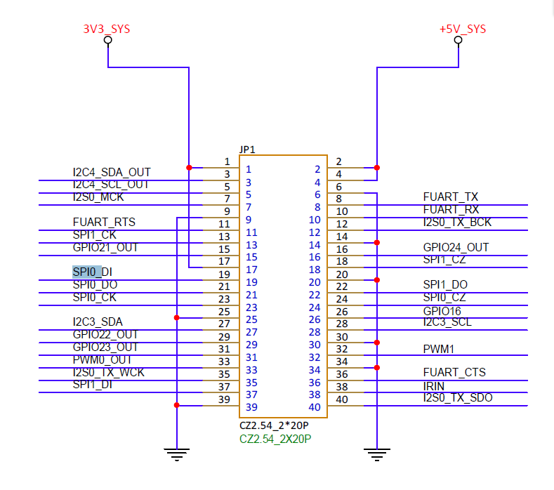
Figure 10-1 SPI Padmux schematic
10.4. Verification Commands
The number of
/devnodes depends on the sum ofcs-num+cs-ext:spidev<bus>.1is created only when the total chip-select count is 2; and only the standard spidev (SPI_SPIDEV) creates /dev nodes — the SGS spidev has no /dev node.
10.5. Related Links
11. I2C
Files involved in this chapter:
mhera_comake_d3_linux_emmc_defconfig/mhera_comake_d3_debian_emmc_defconfig,mhera.dtsi(i2c0~4),mhera-comake-d3-padmux.dtsi(I2C0~4 blocks).
D3 uses 5 I2C groups (I2C0=HDMI DDC, I2C1=panel control, I2C2=PCIE0, I2C3=general purpose, I2C4=PCIE1). The standard defconfig already enables them.
11.1. Kernel Configuration
✅ The standard defconfig already includes them; no change is needed. (debian/linux difference: none)
11.2. DTS Configuration (mhera.dtsi)
Node example (i2c0 as an example, fixed items omitted):
i2c0: i2c@1f222800 {
    compatible = "sgs,i2c";
    // ...
    dma-enable;               // configurable (add to enable)
    group = <0>;              // fixed (I2C hardware number)
    speed = <200000>;         // configurable: 50kHz~1.5MHz
    //t-su-sta = <0>;         // configurable: timing ns (takes effect only when non-zero)
    //t-hd-sta = <0>;          // configurable
    //t-su-sto = <0>;          // configurable
    //t-hd-sto = <0>;          // configurable
    output-mode = <2>;        // configurable: 1=open-drain 2=open-drain+push 1T 3=open-drain+push multi-T 4=push-pull
    status = "ok";            // configurable
};
/* i2c1~i2c4 have the same structure, reg is 0x1F222A00/0x1F222C00/0x1F222E00/0x1F223000 respectively */
Configurable items:
| Item | Meaning | Value |
|---|---|---|
speed |
I2C speed | actual value (e.g. 200000), 50kHz~1.5MHz |
dma-enable |
enable DMA mode | add to enable |
t-su-sta / t-hd-sta / t-su-sto / t-hd-sto |
timing (ns) | 0 by default, takes effect only when non-zero |
output-mode |
output mode | 1=open-drain 2=open-drain+push 1T 3=open-drain+push multi-T 4=push-pull |
status |
enable | "ok" / "disabled" |
group(I2C hardware number),compatible/reg/interrupts/clocks/rd-ack-delayare fixed values; do not modify.
11.3. Padmux Configuration
<PAD_HDMITX_SCL  PINMUX_FOR_I2C0_MODE_1  MDRV_PUSE_HDMI_RX_SCL>,  /* I2C0 */
<PAD_HDMITX_SDA  PINMUX_FOR_I2C0_MODE_1  MDRV_PUSE_HDMI_RX_SDA>,
<PAD_I2C1_SCL    PINMUX_FOR_I2C1_MODE_1  MDRV_PUSE_I2C1_SCL>,     /* I2C1 */
<PAD_I2C1_SDA    PINMUX_FOR_I2C1_MODE_1  MDRV_PUSE_I2C1_SDA>,
<PAD_I2C2_SCL    PINMUX_FOR_I2C2_MODE_1  MDRV_PUSE_I2C2_SCL>,     /* I2C2 */
<PAD_I2C2_SDA    PINMUX_FOR_I2C2_MODE_1  MDRV_PUSE_I2C2_SDA>,
<PAD_I2C3_SCL    PINMUX_FOR_I2C3_MODE_1  MDRV_PUSE_I2C3_SCL>,     /* I2C3 */
<PAD_I2C3_SDA    PINMUX_FOR_I2C3_MODE_1  MDRV_PUSE_I2C3_SDA>,
<PAD_I2C4_SCL    PINMUX_FOR_I2C4_MODE_1  MDRV_PUSE_I2C4_SCL>,     /* I2C4 */
<PAD_I2C4_SDA    PINMUX_FOR_I2C4_MODE_1  MDRV_PUSE_I2C4_SDA>,
Corresponding schematic:
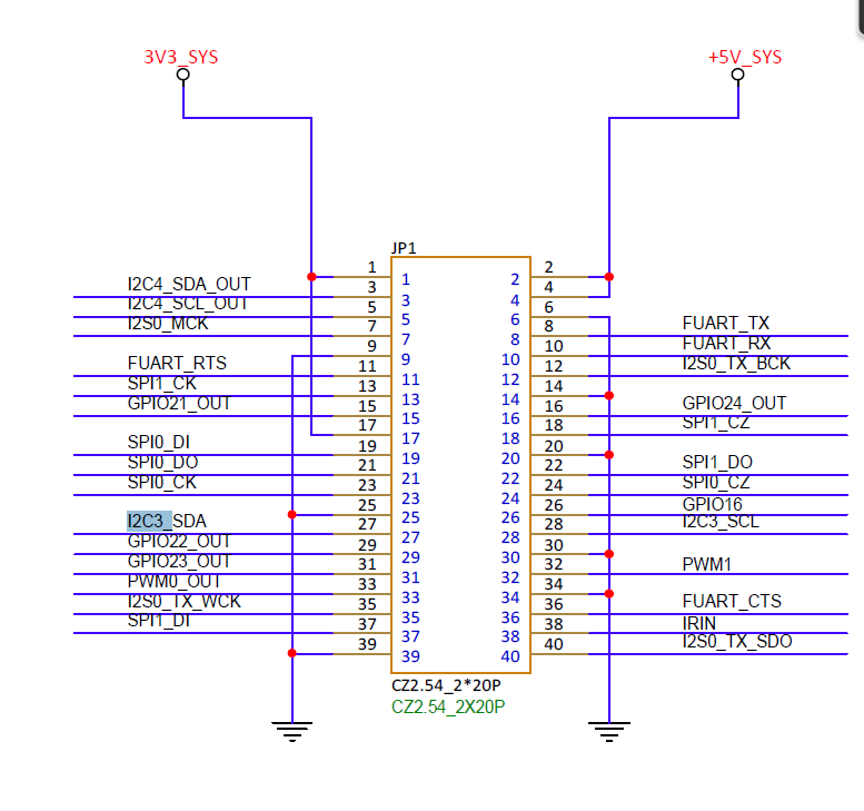
Figure 11-1 I2C Padmux schematic
11.4. Verification Commands
ls /dev/i2c-*        # Expected: i2c-0 ~ i2c-4
i2cdetect -y 0        # Expected: addresses of attached devices are scanned
11.5. Related Links
12. PWM
Files involved in this chapter:
mhera_comake_d3_linux_emmc_defconfig/mhera_comake_d3_debian_emmc_defconfig,mhera.dtsi(pwm0~3),mhera-comake-d3-padmux.dtsi(PWM0/½ blocks).
D3 uses PWM0 for LCD backlight, PWM1 for general purpose, and PWM2 for the fan. The standard defconfig already enables them.
12.1. Kernel Configuration
✅ The standard defconfig already includes them; no change is needed. (debian/linux difference: none)
12.2. DTS Configuration (mhera.dtsi)
Node example (pwm0 as an example, fixed items omitted):
pwm0: pwm@0x1F203200 {
    compatible = "sgs,pwm";
    reg = <0x0 0x1F203200 0x40>;
    interrupts = <GIC_SPI INT_IRQ_PWM_GROUP0 IRQ_TYPE_LEVEL_HIGH>;
    clocks = <&CLK_pwm>;
    #pwm-cells = <3>;
    channel = <0>;            // fixed (0~3)
    group = <0>;              // configurable: 0~3, not added when unset
    clk-select = <0>;         // configurable: clock level
    status = "ok";            // configurable
};
/* pwm1~pwm3 have the same structure, reg is 0x1F203240/0x1F203280/0x1F2032C0 respectively, channel is 1/2/3 respectively */
Configurable items:
| Item | Meaning | Value |
|---|---|---|
clk-select |
clock level | according to the speed range |
group |
whether to join a group | 0/1/2/3, not added when unset |
period |
boot period | normal precision=Hz, high precision=ns |
duty_cycle |
boot duty cycle | normal precision=%, high precision=ns |
polarity |
boot polarity | 0=normal 1=inverted |
status |
enable | "ok" / "disabled" |
channel(0~3),compatible/reg/interrupts/clocksare fixed values; do not modify.
12.3. Padmux Configuration
<PAD_PWM0  PINMUX_FOR_PWM0_MODE_1  MDRV_PUSE_PWM0>,   /* LCD backlight */
<PAD_PWM1  PINMUX_FOR_PWM1_MODE_1  MDRV_PUSE_PWM1>,
<PAD_PWM2  PINMUX_FOR_PWM2_MODE_1  MDRV_PUSE_PWM2>,
Corresponding schematic:
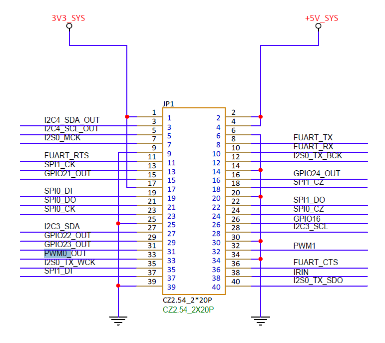
Figure 12-1 PWM Padmux schematic
12.4. Related Links
13. Audio (I2S TX + DMIC)
Files involved in this chapter:
mhera_comake_d3_linux_emmc_defconfig/mhera_comake_d3_debian_emmc_defconfig,mhera.dtsi(soundnode),mhera-comake-d3-padmux.dtsi(I2S0/DMIC/AMP blocks).
D3 supports I2S0 TX audio output (power amplifier) and DMIC digital microphone input. The standard defconfig already enables the audio framework.
13.1. Kernel Configuration
✅ The standard defconfig already includes them; no change is needed. (debian extra:
CONFIG_SND_USB_AUDIO)
13.2. DTS Configuration (the sound node in mhera.dtsi)
Node example (fixed items omitted):
sound {
    compatible = "sgs,audio";
    // ...
    amp-pad = <PAD_UNKNOWN 1 PAD_UNKNOWN 1 PAD_UNKNOWN 1 PAD_UNKNOWN 1>;  // configurable: amplifier pin levels

    /* ... */
    i2s-tx0-tdm-mode    = <1>;   // configurable: 1:master 2:slave
    i2s-tx0-tdm-fmt     = <1>;   // configurable: 1:i2s 2:left justified
    i2s-tx0-tdm-wiremode = <2>;  // configurable: 1:4wire 2:6wire
    i2s-tx0-channel  = <2>;      // configurable: number of channels
    i2s-tx0-soundbar-mode = <1>; // configurable: 0:OFF 1:ON
    // ...

    // DMIC clock mode
    /* 0:not select 1:(8k,600kHz) 2:(8k,1200kHz) ... b:(48k,4800kHz) */
    dmic-bck-mode = <3 6 8 10>;         // configurable
    dmic-bck-ext-mode = <0>;    // configurable: 0=internal 1=I2S RX BCK

    // HPF <switch cutoffHz>
    hpf-adc1-level = <1 20>;    // configurable: <switch cutoffHz>
    hpf-dmic-level = <1 20>;   // configurable: <switch cutoffHz>

    keep-adc-power-on = <0>;   // configurable: 0/1
    keep-dac-power-on = <0>;   // configurable: 0/1
    status = "okay";           // configurable
};
Configurable items:
| Item | Meaning | Value |
|---|---|---|
i2s-tx0/rx0-tdm-mode |
master/slave | 1=master 2=slave |
i2s-tx0/rx0-tdm-fmt |
format | 1=i2s 2=left justified |
i2s-tx0/rx0-tdm-wiremode |
number of wires | 1=4wire 2=6wire |
i2s-tx0/rx0-channel |
number of channels | integer |
i2s-tx0/rx0-tdm-ws-pgm/width/inv/bck-inv |
WS/BCK programmability/width/inversion | see comments |
i2s-tx0-tdm-active-slot |
active slot | bitN→slotN |
dmic-bck-mode |
DMIC clock mode | 0~b (see the comment table) |
dmic-bck-ext-mode |
DMIC clock source | 0=internal 1=I2S RX BCK |
hpf-adc1-level / hpf-dmic-level |
high-pass filter | <switch cutoffHz> |
amp-pad |
amplifier pin levels | <PAD 1 PAD 1 ...> |
keep-adc/dac-power-on |
keep power always on | 0/1 |
status |
enable | "okay"/"disabled" |
compatible/interrupts/clocksand the various*-padmuxvalues are fixed values; do not modify.
13.3. Padmux Configuration
/* I2S0 TX 4-wire */
<PAD_I2S0_MCLK  PINMUX_FOR_I2S0_MCLK_MODE_1  MDRV_PUSE_I2S0_MCK>,
<PAD_I2S0_TX_SDO PINMUX_FOR_I2S0_TX_MODE_1   MDRV_PUSE_I2S0_TX_SDO>,
<PAD_I2S0_TX_WCK PINMUX_FOR_I2S0_TX_MODE_1   MDRV_PUSE_I2S0_TX_WCK>,
<PAD_I2S0_TX_BCK PINMUX_FOR_I2S0_TX_MODE_1   MDRV_PUSE_I2S0_TX_BCK>,
/* DMIC (8CH mode) */
<PAD_PM_GPIO1   PINMUX_FOR_DMIC_8CH_MODE_1  MDRV_PUSE_DMIC0_CLK>,
<PAD_PM_GPIO6   PINMUX_FOR_DMIC_8CH_MODE_1  MDRV_PUSE_DMIC0_D0>,
<PAD_PM_GPIO7   PINMUX_FOR_DMIC_8CH_MODE_1  MDRV_PUSE_DMIC0_D1>,
<PAD_SATA_GPIO0 PINMUX_FOR_DMIC_8CH_MODE_1  MDRV_PUSE_DMIC0_D2>,
<PAD_SATA_GPIO1 PINMUX_FOR_DMIC_8CH_MODE_1  MDRV_PUSE_DMIC0_D3>,
/* amplifier power control (GPIO mode) */
<PAD_GPIO19     PINMUX_FOR_GPIO_MODE        MDRV_PUSE_AIO_AMP_PWR>,
Corresponding schematic:
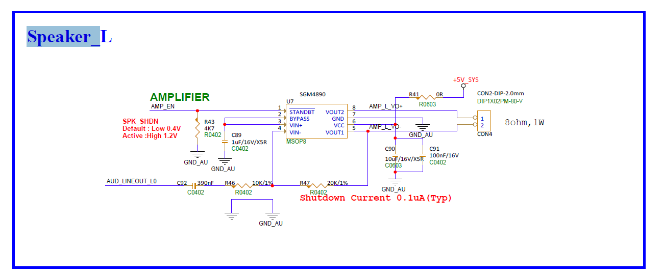
Figure 13-1 Audio (I2S) schematic
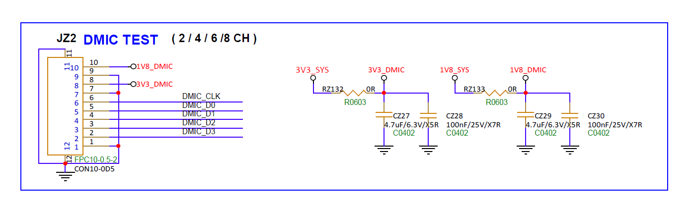
Figure 13-2 Audio (DMIC/amplifier) schematic
13.4. Verification Commands
cat /proc/asound/cards   # Expected: sound cards are listed
aplay -l                 # Expected: playback devices are listed
13.5. Related Links
14. GPIO and PAD_INIT
Files involved in this chapter:
mhera_comake_d3_linux_emmc_defconfig/mhera_comake_d3_debian_emmc_defconfig,mhera.dtsi(gpio node),mhera-comake-d3-padmux.dtsi(schematic + pad_init).
14.1. Kernel Configuration
CONFIG_GPIOLIB=y
CONFIG_GPIO_SYSFS=y        # /sys/class/gpio interface
CONFIG_SGS_PAD_INIT=y      # pin initial state driver
(The pull-up/down and driving-strength sysfs interface requires enabling CONFIG_MSYS_GPIO separately)
14.2. DTS Configuration
The gpio node (mhera.dtsi):
gpio {
    compatible = "sgs,gpio";
    #gpio-cells = <2>;   /* cell0=gpio number, cell1=active level */
    status = "okay";   // configurable
};
Ordinary GPIOs need no extra configuration; #gpio-cells is a fixed value.
14.3. Padmux Configuration
Reuse functions: the schematic list <PAD_xxx PINMUX_FOR_xxx_MODE_n MDRV_PUSE_xxx>; GPIO mode uses PINMUX_FOR_GPIO_MODE.
Power-on default state: the pad_init node configures the default direction/level/pull-up-down/driving strength of the pins at power-on (the pins are already in this state before the kernel starts and before drivers load, ensuring that the peripheral power/reset pins are at the correct level at the moment of power-on). The actual D3 configuration:
pad_init {
    schematic =
        <PAD_PM_GPIO0   GPIO_DIR_OUT  GPIO_LEVEL_HIGH  PAD_PULL_DEFAULT  PAD_DRV_DEFAULT>,   // configurable
        <PAD_SAR_GPIO2  GPIO_DIR_OUT  GPIO_LEVEL_HIGH  PAD_PULL_DEFAULT  PAD_DRV_DEFAULT>,   // configurable
        <GPIO_NR        GPIO_DIR_NA   GPIO_LEVEL_NA    PAD_PULL_DEFAULT  PAD_DRV_DEFAULT>;
};
PAD_PM_GPIO0output-high is a D3 development board specific setting: this pin controls the baseboard peripheral power and is pulled high at power-on to supply the peripherals. If your board has a different power control pin (or does not need one), change it to the corresponding pin or delete the line;PAD_SAR_GPIO2(system LED) is the same. Format:<Pad_Index Direction Level Pull Driving>with valuesGPIO_DIR_IN/OUT/NA,GPIO_LEVEL_HIGH/LOW/NA,PAD_PULL_UP/DOWN/HIZ/DEFAULT,PAD_DRV_0/1/2/.../DEFAULT.
14.4. Related Links
15. Memory Configuration
Memory usually has multiple allocation cases, and understanding the board's memory allocation is very important for development. This chapter uses the Comake D3 development board as an example to introduce how to view, understand, and configure the board's memory allocation.
15.1. Configuration Viewing and Modification
Take the linux defconfig of D3 as an example; open project/configs/demo/defconfigs/linux-comake_mhera.emmc.glibc-12.4.0-arm64-ext4.d3.4096.fccsp16_lpddr4x_defconfig, and you can see:
CONFIG_DRAM_SIZE="0x100000000"
CONFIG_LX_MEM_SIZE="0x100000000"
CONFIG_MMA_MEM_SIZE="0x20000000"
CONFIG_CMA_MEM_SIZE="0x400000"
CONFIG_LOGO_MEM_SIZE="0x800000"
CONFIG_FB_MEM_SIZE="0x4048000"
These are the memory allocation settings:
| Config item | Value | Description |
|---|---|---|
| CONFIG_DRAM_SIZE | 0x100000000 | Total DRAM size = 4GB |
| CONFIG_LX_MEM_SIZE | 0x100000000 | Linux available memory = 4GB |
| CONFIG_MMA_MEM_SIZE | 0x20000000 | Multimedia / dedicated memory = 512MB |
| CONFIG_CMA_MEM_SIZE | 0x400000 | CMA (contiguous memory allocation) = 4MB |
| CONFIG_LOGO_MEM_SIZE | 0x800000 | Logo display buffer = 8MB |
| CONFIG_FB_MEM_SIZE | 0x4048000 | Framebuffer = ~64.28MB |
It can be seen that DRAM_SIZE corresponds to the actual DDR memory size. Here LX_MEM_SIZE, i.e. the available memory allocated to Linux, takes the entire 4GB. This is because MMA, CMA, LOGO, and FB are all taken out of LX_MEM:
The Linux available memory here corresponds to what cat /proc/meminfo shows. Substituting into the formula:
DRAM_SIZE(4GB)=LX_MEM_SIZE(4GB)≈Linux available memory+MMA_MEM_SIZE(512MB)+CMA_MEM_SIZE(4MB)+LOGO_MEM_SIZE(8MB)+FB_MEM_SIZE(64.28MB)
Because of rounding, this is approximate, but the corresponding allocation relationship (inclusion) can be seen.
15.2. Memory Allocation Description
- Linux available memory: memory visible to Linux, for programs under the kernel to apply for and use.
- MMA_MEM: memory provided to MIU, dedicated to internal use by MI modules or applied by MIU. It is a separately divided memory pool, so Linux cannot see it and it is not included in meminfo.
- CMA_MEM: a contiguous physical memory pool reserved for hardware DMA, allowing drivers to dynamically allocate large contiguous buffers to avoid allocation failures caused by memory fragmentation.
- LOGO_MEM: memory occupied by the boot logo at startup.
- FB_MEM: Framebuffer, provided to fb as video memory.
Also note that MMA uses 64-bit addresses and may use a 10E address as the start offset, so the allocated address may exceed the 32-bit representable range; while the fbdev address in the kernel is represented with 32 bits. If MMA is used directly, the address will overflow/be truncated, causing memory corruption or data loss. Therefore a separate block is reserved for fb.
15.3. Viewing from boot
Memory allocation is passed to the kernel through bootargs. We can also understand the current board's memory configuration by viewing bootargs. The bootargs specifies the memory allocation in this format, corresponding to the defconfig. Since memory is allocated to the kernel through bootargs, for temporary modification you can also use setbootargs xxxxxxx to manually modify the memory allocation state.
15.4. Related Links
16. Appendix A: Configuration File Path Overview
| Category | Path |
|---|---|
| Project Defconfig (linux) | project/configs/demo/defconfigs/linux-comake_mhera.emmc.glibc-12.4.0-arm64-ext4.d3.4096.fccsp16_lpddr4x_defconfig (there is also a 2048 memory variant) |
| Project Defconfig (debian) | project/configs/demo/defconfigs/debian-comake_mhera.emmc.glibc-12.4.0-arm64-ext4.d3.4096.fccsp16_lpddr4x_defconfig |
| Kernel Defconfig (linux) | kernel/arch/arm64/configs/mhera_comake_d3_linux_emmc_defconfig |
| Kernel Defconfig (debian) | kernel/arch/arm64/configs/mhera_comake_d3_debian_emmc_defconfig |
| U-Boot Defconfig | boot/configs/mhera_comake_d3_emmc_arm64_defconfig |
| U-Boot DTS | boot/arch/arm/dts/mhera-comake-d3.dts (+ mhera-comake-d3-padmux.dtsi) |
| SDK Generic Defconfig | project/configs/generic/defconfigs/mhera_sdk_generic_defconfig |
| Partition table (linux) | project/image/configs/general/emmc_linux-comake.ext4fs.tfa.partition.config |
| Partition table (debian) | project/image/configs/general/emmc_debian-comake.ext4fs.tfa.dualenv.partition.config |
| Board-level DTS (linux) | kernel/arch/arm64/boot/dts/sgs/mhera-comake-d3-purelinux.dts |
| Board-level DTS (debian) | kernel/arch/arm64/boot/dts/sgs/mhera-comake-d3-debian.dts |
| SoC-level DTS | kernel/arch/arm64/boot/dts/sgs/mhera.dtsi |
| Display subsystem | kernel/arch/arm64/boot/dts/sgs/mhera-display-subsystem.dtsi |
| Padmux | kernel/arch/arm64/boot/dts/sgs/mhera-comake-d3-padmux.dtsi |
| Panel parameters (kernel side) | kernel/arch/arm64/boot/dts/sgs/panel-*.dtsi |
| Board-level configuration | project/board/mhera/D3/config/{config_board.json, config_fb.json, config.json} |
| Panel parameters (SDK side) | project/board/mhera/screen_param/config_disp.json |
16.1. Schematic Page Index
Each PAD_xxx in Padmux corresponds to a net on the schematic. The corresponding circuit figures have been inserted in each chapter; to view the complete pages, open the corresponding page of the original PDF:
| Peripheral / Padmux | Schematic page |
|---|---|
| MIPI DSI | page 8 |
| HDMI_TX | page 9 |
| RGMII0 / RGMII1 (GMAC) | page 7 |
| USB (P0/P2 Host, USB3) | page 10 |
| SATA_P0 / SATA_P1 | page 13 |
| SD card (SD0) | page 5 |
| DMIC / Debug UART / GPIO | page 3 |
| Audio (MIC / Speaker / AMP) | page 6 |
| SPI / I2C / PWM / PCIe / UART1~3 | page 2 (golden finger / overview) |
The eMMC is on the core board and is not in the schematic of this baseboard (D3_BASE).
17. Appendix B: Per-Peripheral Default Enable/Disable Status Summary
| Peripheral | Kernel config | DTS node | Padmux status | Enabled | debian/linux difference |
|---|---|---|---|---|---|
| MIPI DSI | FB (linux) / DRM (debian) | mipi_dsi + panel dtsi + board-level dts | ✅ #if 1 |
✅ | Different frameworks: linux=FB/mi_disp, debian=DRM; there are also two copies of the board-level dts, debian fixes HDMI→disp0, MIPI→disp1 |
| HDMI | same as above | hdmi | ✅ #if 1 |
✅ | same as above |
| Touch GT911 | TOUCHSCREEN_GOODIX (linux) / HID_MULTITOUCH (debian) |
goodix_gt911@5d (board-level dts) | GPIO17/18 | ✅ | linux uses the goodix driver, debian uses HID/evdev |
| GMAC0/1 | CONFIG_SGS_GMAC (default y) + STMMAC |
gmac0/gmac1 | ✅ #if 1 (RGMII) |
✅ | none |
| USB | USB_XHCI/EHCI/STORAGE + SGS PHY |
sgs-ehci-½, usb3drd_p2/p3 | ✅ VBUS | ✅ | linux extra USB_SERIAL/RNDIS; debian extra UVC/CH341/CP210X |
| SATA | SATA_AHCI_PLATFORM + SGS_SATA_HOST |
sata/sata1 | — | ✅ | none |
| PCIe | SGS_PCIE_HOST/EP/HOTPLUG |
pcie0/pcie1 | GPIO21=PCIE1_PERST | ✅ | none |
| eMMC/SD | MMC + SGS_SDMMC + SD30/EMMC50 |
sgs_sdmmc0/1 | ✅ conditional | ✅ | none |
| UART | SGS_UART |
fuart/uart0~3 | ✅ FUART/UART½/3 | ✅ | none |
| SPI | SPI + SGS_MSPI + (SPI_SPIDEV or SGS_SPI_DEVICE) |
spi0/spi1 | ✅ SPI0/1 | ✅ | none |
| I2C | I2C + I2C_CHARDEV + SGS_I2C |
i2c0~4 | ✅ I2C0~4 | ✅ | none |
| PWM | PWM |
pwm0~3 | ✅ PWM0/½ | ✅ | none |
| Audio | SND/SND_SOC/SGS_SND_SOC |
sound | ✅ I2S0/DMIC/AMP | ✅ | debian extra SND_USB_AUDIO |