Alkaid Defconfig
REVISION HISTORY
| Revision No. | Description |
Date |
|---|---|---|
| 1.0 | 02/01/2024 | |
| 1.1 | 05/29/2024 | |
| 1.2 | 06/03/2024 | |
| 1.3 | 07/02/2024 | |
| 1.4 | 08/12/2024 | |
| 1.5 | 08/12/2024 | |
| 1.6 | 03/12/2025 | |
| 1.7 | 03/31/2025 | |
| 1.8 | 05/27/2025 | |
| 1.9 | 09/19/2025 | |
| 1.10 | 10/13/2025 | |
| 1.11 | 02/05/2026 |
1. Overview
1.1. Functional Description
alkaid defconfig is the top-level configuration file of the entire project compilation environment. defconfig provides a graphical configuration interface based on menuconfig.
To display the menuconfig interface, please refer to the environment setup document to set up the toolchain and execute in the project directory:
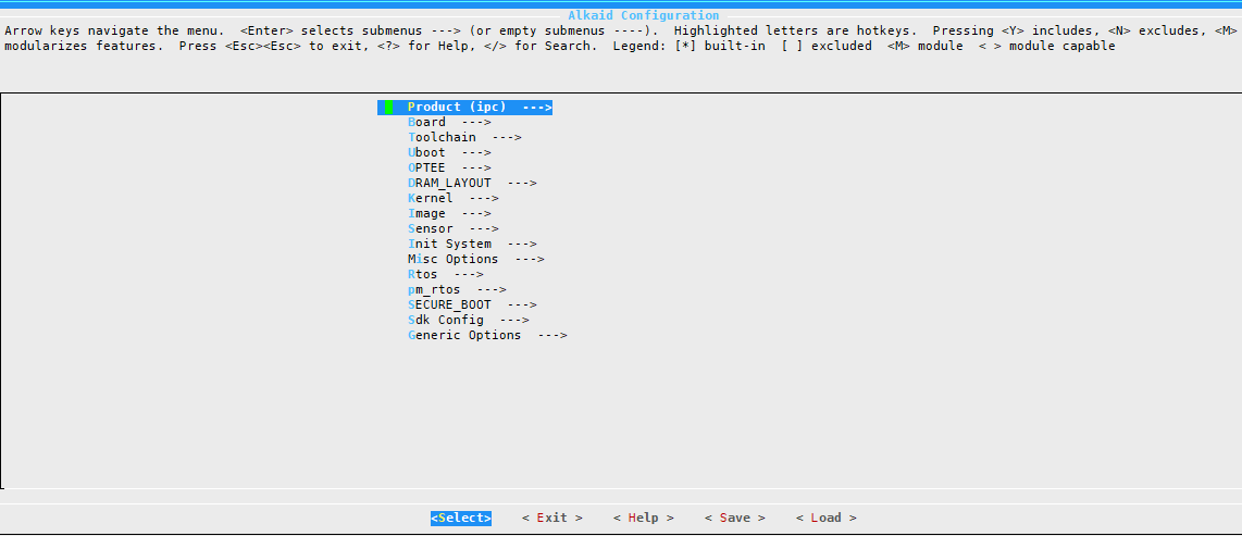
Figure 1-1 alkaid defconfig corresponding menuconfig graphical interface
The main configuration items of alkaid defconfig are as follows:
- Product
- Board
- Toolchain Configuration
- Uboot Configuration
- OPTEE
- DRAM_LAYOUT Configuration
- Linux Kernel Configuration
- Image Packaging Related Configuration
- Camera Sensor Configuration
- Init System
- Misc Option Configuration
- RTOS Configuration
- Vmm
- pm_rtos
- Android
- SECURE_BOOT
- Sdk Configuration
- PMIC
- Generic Options
1.2. Document format constraints
Traditional font: Used for writing the main body of the document, where code snippets need to be written in a monospaced font.
Regular + Bold: Used to write important content in the body of the document.
Italic: Used for writing in the Tips section of the document.
Italic + Bold: Used to write important content in the Tips section of the document.
1.3. Keyword Description
NVR: Network Video Recorder.
DVR: Digital Video Recorder, or digital hard disk recorder.
XVR: X (representing any one or more functions) Video Recorder. The current SGS implementation is NVR+DVR.
IPC: IP Camera, i.e. network camera.
USBCAM: USB Camera.
CARDV: Car Digital Video.
DISPCAM: Display Camera, i.e. camera screen display.
Android: A free and open source mobile operating system based on the Linux kernel (excluding GNU components).
IPC-RTOS: SGS's self-developed dual system, which can run Linux and RTOS systems at the same time, taking into account the lightweight of RTOS and the powerful scalability of Linux, to realize the characteristics of quick startup.
DualOs: Same as IPC-RTOS.
2. Product
Product forms include ipc, nvr, usbcam and other different solutions. Different solutions have different default scenarios, so the packaged configuration files and running bins are different. Please refer to different product forms to use different software solutions for configuration.
3. Board
Development board related hardware and software configuration.
3.1. Board
The development board model is usually almost unchanged after it is determined in the bringup stage. It is normal for the model to be different from the model in the defconfig file name. This parameter will affect some configurations during code compilation. Taking iFord as an example, the ko configuration installed by default at startup is in:
If different boards require different configurations, refer to this path to add configurations.
3.2. Board Name
The full name of the development board model, which generally does not need to be modified. This parameter will affect some configuration scripts used in the image packaging process. Take iFord as an example:
Some config.json files will be saved in the directory.
If different boards require different configurations, refer to this path to add configurations.
4. Toolchain
Toolchain configuration is usually determined before bringup and will not be modified unless a chip supports multiple toolchains (if compatibility issues are resolved).
4.1. LinuxArch
The Linux operating architecture is related to the soc core solution. SGS currently mainly adopts the arm solution.
4.2. Toolchain
Toolchain solution. SGS currently supports glibc, uclibc, and llvm. Please refer to the environment construction for toolchain settings. Once the solution is determined, it will not be modified. This parameter affects the release installation path, so modification should be cautious. Take iFord as an example:
This directory will install some pre-compiled libs and the products of the compilation process for use in the subsequent image packaging stage.
4.3. Toolchain Version
The software version corresponding to the toolchain solution. The parameters are affected as above.
4.4. Toolchain Rel
Toolchain prefix, which is determined during bringup and generally does not need to be modified. Take iFord as an example:
This configuration will be used in the makefile to form the full name of gcc for use.
sdk/verify/sample_code/mi_dep.mk
25:TOOLCHAIN_REL := $(CROSS_COMPILE)
26:TOOLCHAIN_VERSION := $(shell $(TOOLCHAIN_REL)gcc -dumpversion)
Since we added the toolchain path to the PATH environment variable when we set up the environment, we can directly call the corresponding instructions using the name.
$ which  arm-linux-gnueabihf-11.1.0-gcc
/tools/toolchain/gcc-11.1.0-20250211-linaro-glibc-x86_64_arm-linux-gnueabihf/bin/arm-linux-gnueabihf-11.1.0-gcc
5. Uboot
5.1. Uboot build config
Uboot configuration file, used to compile the config file of uboot. Due to different hardware and software configurations, it is necessary to match the development board model. The corresponding config path is:
5.2. uboot Bin
uboot bin name, generally no need to modify. This parameter will specify the corresponding img file from the boot directory to the project directory for alkaid image packaging. When the development board is powered on, ipl will load uboot.bin and decompress it into ram to run. Therefore, different compression formats of uboot will affect the size of uboot.bin and the decompression speed.
5.3. Uboot Version
The uboot version is determined by the boot directory code version and will not be modified midway. Because different uboot versions accept different parameters, some configuration files will use different uboot parameters based on this configuration.
5.4. Uboot DTBO LIST
Android DTBO list. Currently, this configuration only supports Opera.
6. OPTEE
6.1. OPTEE OS make Option
OPTEE compile options, used to pass make parameters to its makefile.
Kernel version, taking souffle as an example, the kernel version is 5.10. Generally, it is determined during bringup. If you need to support other kernel versions, please submit a market request.
6.2. OPTEE Test
Enable and disable compilation of OPTEE test items.
6.3. OPTEE UT
Enable and disable compilation of OPTEE UT items.
6.4. OPTEE client TEE file system with FirmwareFS
Enable and disable compilation of OPTEE FirmwareFS support.
6.5. OPTEE client compile Option
Set the toolchain for the OP-TEE client.
7. DRAM_LAYOUT
Adjust the size of each runtime module
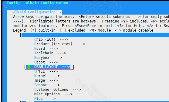
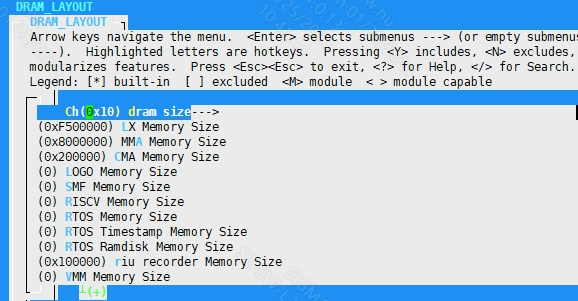
After make defconfig, dram_layout.txt will be generated in the project\configs directory
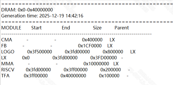
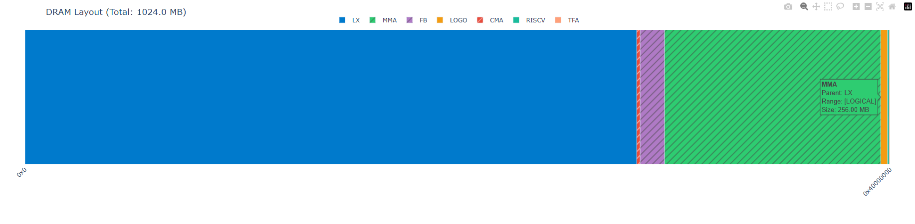
The following diagram shows a typical DRAM layout for the Pcupid platform. You can generate such a view by running python scripts/dram_layout_graph.py --input configs/dram_layout.txt --output configs/dram_layout.html, which helps verify module address ranges and relative placement. Solid-color blocks represent modules with fixed addresses, while the hatched overlays indicate virtual subregions whose addresses are inferred from their parent; these virtual blocks occupy simulated spaces for sizing purposes only and do not correspond to actual load positions.
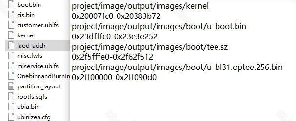
After making the image, it will check whether the laod addr of each runtime module overlaps. It will generate laod_addr.txt in the project\image\output\images directory.
7.1. dram size
Dram memory size
7.2. LX Memory Size
Linux system available memory
7.3. MMA Memory Size
The memory size occupied by MMA
7.4. CMA Memory Size
The memory size occupied by CMA
7.5. LOGO Memory Size
The memory size of the logo
7.6. RISCV Memory Size
The memory size of RISCv
7.7. RTOS Memory Size
The memory size of RTOS
7.8. RTOS Timestamp Memory Size
The memory size of rtos timestamp
7.9. RTOS Ramdisk Memory Size
The memory size of the rtos ramdisk partition
7.10. earlyinit Memory Size
The memory size of earlyinit
7.11. VMM Memory Size
The memory size of VMM
7.12. OPTEE Memory Size
The memory size of optee
7.13. TF-A Memory Size
The memory size of tf-a
7.14. enable to modify TF-A load address
If not set, will use tf-a default loading address.
7.15. FB Memory Size
The memory size of FB
8. Kernel
8.1. Kernel Version
Kernel version. Take Souffle as an example, the kernel version is 5.10. Usually it is determined during bringup. If you need to support other kernel versions, please inform us.
8.2. Kernel Config
Kernel configuration file, used to compile the config file of the Linux kernel. Due to different hardware and software configurations, it is necessary to match the development board model. The corresponding config path is:
8.3. kernel Bin
Kernel bin name, generally no need to modify
8.4. sgs intercore manger
sgs intercore manger is used to communicate cm4/riscv with cortex-a.
8.5. Kernel DTB NAME
Kernel dtb name
8.6. Kernel DTBO NAME
Kernel dtbo name
8.7. Kernel DTBO LIST
Kernel dtbo list
8.8. SELinux
8.8.1. Support SELinux bool
Support SELinux (y/n)
8.8.2. Support SELinux string
Support SELinux (on/off)
8.8.3. SELINUX mode
SELinux mode selection
8.8.4. SELINUX policy path
SELinux policy path selection
8.9. Maximum expected bad eraseblock count per 1024 eraseblocks
Number of ubi bad blocks reserved for overwriting uboot/kernel configuration
8.10. Extra Kernel Boot Arguments
A flexible and configurable way to add extra kernel boot arguments, such as “vmalloc=600M param_a=aa param_b=bb”
9. Image
9.1. Using Customize Image Config
Whether to use the customer's own partition configuration. When packaging the image, the customer's own partition configuration file will be searched from the following path.
9.2. Image Partition Config
Partition configuration file name. For detailed configuration of this file, please refer to System Partition.
The partition configuration varies depending on the flash type, rootfs type, and whether pm_rtos is used. Please configure according to your needs.
9.3. IPL File Config
The name of the IPL file. The path to this file is set in the Image Partition Config file.
9.4. IPL_CUST File Config
The name of the IPL_CUST file. The path to this file is set in the Image Partition Config file.
9.5. IPLX File Config
The name of IPLX file. This file is only used by emmc flash. The path of this file is set in the Image Partition Config file.
9.6. USB Upgrade Image
USB upgrade uses the following images
9.6.1 USB_UPGRADE_IPL_CONFIG
The IPL file name used to create the USB factory upgrade image.
The name of the riscv firmware, currently only used by opera. This configuration takes effect during the image packaging process, and the file path is configured in the corresponding file of Image Partition Config.
9.6.2 USB_UPGRADE_TFA_CONFIG
The tf-a file name used to create the USB upgrade image.
9.7. SD Upgrade Image
SD upgrade uses the following images
9.7.1 SD_UPGRADE_IPL_CONFIG
The IPL image used for SD upgrade
9.7.2 SD_UPGRADE_IPL_CUST_CONFIG
The IPL_Cust image used for SD upgrade
9.7.3 SD_UPGRADE_TFA_CONFIG
The TF-A image used for SD upgrade
9.8. UART BOOT Image
UART upgrade uses the following images
9.8.1 UART_BOOT_IPL_CONFIG
The IPL image used for UART upgrade
9.8.2 UART_BOOT_IPL_CUST_CONFIG
The IPL_Cust image used for UART upgrade
9.8.3 UART_BOOT_TFA_CONFIG
The TF-A image used for UART upgrade
9.9. TF-A File Config
The name of the TF-A bin file. The path of this file is set in the Image Partition Config file.
9.10. OPTEE File Config
The name of the OPTEE bin file. The path of this file is set in the Image Partition Config file. After configuration, optee will be compiled and some dependent files will be packaged into the image during compilation.
9.11. VMM File Config
The name of the VMM bin file. The path of this file is set in the Image Partition Config file.
If HYP is selected for LH or HYP of Dualos Type, the correct VMM bin name must be filled in here.
9.12. Flash Size
Take effect only when the Flash type is nor. This configuration is currently deprecated.
9.13. EMMC BOOT_PART.bin support backups
emm boot.bin backup function.
9.14. riscv
riscv is configured for CHIP with riscv hardware, which is another set of hardware and software architecture independent of arm.
9.14.1. riscv enable
The riscv function is enabled. This configuration takes effect during compilation and packaging.
9.14.2. riscvfw Bin
The riscvfw Bin name copied when packaging the image. This configuration takes effect during the image packaging process, and the file path is configured in the corresponding file of Image Partition Config.
9.14.3. riscv build toolchain
Compile the toolchain used by riscv, please refer to the environment setup. This configuration takes effect during compilation.
9.14.4. riscv build config
The name of the config file used to compile riscv. This configuration takes effect during compilation.
9.15. pm51
pm configuration option
9.15.1 pm51 Bin
The name of the pm firmware, currently only used by opera. This configuration takes effect during the image packaging process, and the file path is configured in the corresponding file of Image Partition Config.
9.16. Support cm4 preload Image
Package mi modules into dualos image
9.17. Support AOV Image
Package the MI module into dualos and compile it into AOV image.
9.18. STRIP OPTION
Setting it to strip unneeded can delete more symbols and reduce ko
9.19. dla firmware
The name of the riscv firmware, currently only used by opera. This configuration takes effect during the image packaging process, and the file path is configured in the corresponding file of Image Partition Config.
9.20. libs list to remove
Used to filter the libs that do not need to be packaged into miservice.
9.21. Whether to enable the addition of dependency for mi libs
It is used to enable or disable the function of adding dependencies to the dynamic library of the MI module.
10. Sensor
10.1. enable sensor
Enable sensor
10.2. IQ0
The IQ bin to be packaged is in the path of project/board/${CHIP}/iqfile/. The file will be installed in the misc/iqfile directory.
10.3. IQ1
The IQ bin to be packaged is in the path of project/board/${CHIP}/iqfile/. The file will be installed in the misc/iqfile directory.
10.4. IQ2
The IQ bin to be packaged is in the path of project/board/${CHIP}/iqfile/. The file will be installed in the misc/iqfile directory.
10.5. IQ3
The IQ bin to be packaged is in the path of project/board/${CHIP}/iqfile/. The file will be installed in the misc/iqfile directory.
10.6. IQ API Bin List
Package the iq file in project/board/${chip}/iqfile/${IQ_API_LIST} into the image.
10.7. Sensor List
The list of sensor drivers installed by default in image. The ko in the list will be automatically insmoded at boot time.
This item does not need to be configured when using dualos.
10.8. Sensor0
Set the corresponding ko for Sensor0
10.9. Sensor0 Opt
Set the insmod parameters for the ko corresponding to Sensor0.
This does not need to be configured when using dualos.
10.10. Sensor1
Set the corresponding ko for Sensor1
10.11. Sensor1 Opt
Set the insmod parameters for the ko corresponding to Sensor1.
10.12. Sensor2
Set the corresponding ko for Sensor2
10.13. Sensor2 Opt
Set the insmod parameters for the ko corresponding to Sensor2.
10.14. VCM List
List of motors that control sensor zoom
10.15. VCM0
Motor 0 for controlling sensor zoom
10.16. VCM0 Opt
Set parameters for VCM0
10.17. VCM1
Motor 1 for controlling sensor zoom
10.18. VCM1 Opt
Set parameters for VCM1
10.19. VCM2
Motor 2 for controlling sensor zoom
10.20. VCM2 Opt
Setting parameters for VCM2
11. Init System
11.1. Init System
Select the Init System type, currently busybox/systemd is supported.
11.2. Busybox
Busybox uses files that are compiled and packaged using the toolchain in the environment setup. The corresponding file storage path is:
Users can add and modify busybox according to their needs. The busybox compressed package will be installed in the corresponding file directory during the alkaid image packaging process.
11.3. Systemd
Set the name of the compressed package, such as systemd-246.5-arm-linux-gnueabihf-glibc-linaro-11.1.0-dynamic.
11.4. Using systemd-bootchart For Profile Startup Time
Set whether to select systemd-bootchart as the init program for analyzing boot time.
12. Misc Options
12.1. Fpga
Used to mark the internal chip development stage of deconfig.
12.2. Fz1
Used to mark the internal chip development stage of deconfig.
12.3. Bench
Used to mark the internal chip development stage of deconfig.
12.4. TFTP Download Addr
The cache address of the file when uboot performs TFTP download. The default value is 0x21000000.
12.5. Kernel Boot Addr
The kernel startup address, the default value is 0x23000000. This item is used for uboot, so directly loading kernel/boot kernel via ipl is not controlled by this item, so this item is invalid for DualOs.
12.6. Init Ramfs Addr
The memory start address where Ramfs is located. The kernel will mount rootfs through this address when it starts. The default value is 0x21800000.
12.7. Split Each File Size
Split into larger partition bins to avoid using too much memory during burning and stepping on the subsequent memory data. The default value is 0x2000000.
12.8. upgrade_type
The firmware upgrade method affects the automatic burning command when entering uboot.
12.9. which mmc device is the SD upgrade card
The mmc device number used for SD upgrade. This configuration is only effective when upgrade_type is set to sd.
12.10. kernel module list that only packs into image but not insmod
Custom kernel modules that are only packaged into the image but not insmod in demo.sh, convenient for adding debug-only ko.
12.11. customized linux modparam.json files
Custom purelinux modparam.json file needs to be placed in the board/$(CHIP)/json/$(PRODUCT)/ directory.
12.12. use ab system boot
Use a/b to back up partitions
12.13. debug tools
Copy the debug tools to the /customer directory.
12.14. AppArmor support
Pack apparmor prebuild tool and profile to rootfs and enable apparmor function.
12.15. sgs_wifi
12.15.1. sgs_wifi
The ko driver corresponding to WiFi is installed by default. If the product you maintain does not require WiFi, you do not need to worry about this parameter.
12.16. SSH
SSH tool packaging option. This option takes effect during the image packaging stage.
12.16.1. Support SSH
Whether to support SSH
12.17. BOOTLOGO
BOOTLOGO option. This option is currently used in Opera to configure bootcmd, and the chip after iford is used to package the configuration files and images required for the bootlogo.
12.17.1. Support BOOTLOGO
Whether to support BOOTLOGO
12.17.2. bootlogo command (0)
The bootlogo command for display device 0 in the U-Boot bootcmd.
Default is "bootlogo". For multi-display scenarios (e.g. HDMI + MIPI simultaneously), set to "bootlogo 1 0 0 0 0 0".
12.17.3. bootlogo command (1)
The bootlogo command for display device 1 in the U-Boot bootcmd.
Default is empty. For multi-display scenarios (e.g. HDMI + MIPI simultaneously), set to "bootlogo 0 0 0 0 1 0".
12.18. BOOTMUSIC
BOOT MUSIC option. This option takes effect during the image packaging stage.
12.18.1. Support BOOTMUSIC
Whether to support BOOTMUSIC
12.18. PQ
PQ option. This option takes effect during the image packaging stage.
12.18.1. Support PQ
Whether to support PQ
12.19. Basic rootfs file name
rootfs option. This option takes effect during the image packaging stage under debian config, used to specify the debian rootfs filename (default: debian-arm64.tar.gz, placed in project/image/rootfs/).
13. Rtos
13.1. Rtos enable
Enable RTOS compilation. This configuration takes effect during compilation and packaging.
Pure Linux system does not need to configure this item, please make sure all functions are disabled
13.2. rtos Bin
The name of the Rtos image file, the default is rtos.sz.
13.3. RtosType
When RTOS compilation is enabled, you can compile and package the system type selection, currently supporting pure rtos and dualos options. This configuration takes effect during compilation and packaging.
13.4. LH or HYP of Dualos Type
When RtosType is set to dualos, you need to configure the dualos solution. Currently SGS supports two solutions: light SMPLH (LH) and hypervisor (HYP). This configuration takes effect during compilation and packaging.
13.5. Rtos build toolchain
The tool chain used to compile Rtos is consistent with the environment setup. This configuration takes effect during compilation and packaging.
13.6. Rtos build config
The name of the config file used to compile Rtos. This file is located in the rtos directory. This configuration takes effect during compilation and packaging.
13.7. Support Sensor driver in RTOS
Compile the sensor driver and enter rtos.
13.8. Config RTOS compile all Sensor Driver
Whether to compile all Sensor Drivers in the RTOS system. The default value is n.
13.9. Support Linux destroy rtos mi resource by MI_SYCALL
Support MI_SYSCALL to destroy multi-process resources created by rtos. If it is disabled, only rtos can destroy multi-process resources created by rtos
13.10. Earlyinit Options
Earlyinit options
13.10.1. Select Earlyinit Mode
Choose earlyinit mode.
13.10.2. Set Earlyinit Setting Default Json Name
Set the json name to be converted to header and use it as the default earlyinit setting.
13.10.3. Set Earlyinit Setting Built-in Json Name List
Set the json name list to be converted into header, separated by space.
bootargs_rtos add earlyinit_json=$(your_json_name), where $(your_json_name) is the corresponding json name.
13.10.4. Support Dynamically Load Earlyinit Setting From File System
Support for loading earlyinit settings from the file system at boot time.
13.10.5. Bitmap for early init enable
The enabled earlyinit sensor bitmap is obtained by ORing one or more sensor chn maps.
13.10.6. Support Vif pipe line create
Enable VIF to create pipeline in earlyinit.
13.10.7. EarlyInit log level
Earlyinit log level setting
13.10.8. Support sensor CM4
Enable CM4 to use sensor.
13.10.9. Support MIPI RX 2Lane mode
Enable MIPI RX 2Lane.
13.10.10. Support earlyinit light sensor enable
Support earlyinit using light sensor.
13.10.11. Support skip earlyinit in cold boot
Support skipping earlyinit in cold boot.
13.10.12. Support MIPI 2+2 lane mode
Enable MIPI RX 2+2 Lane mode.
13.10.13. Sensor PAD0 preset ID
Select the IPL stage earlyinit setting for Sensor PAD0
13.10.14. Sensor PAD2 preset ID
Select the IPL stage earlyinit setting for Sensor PAD2
13.10.15. Enable earlyinit IPL log
Enable IPL Stage earlyinit Debug Messages. Turning this on may increase the Time-To-First-Frame (TTFF) latency following system power-up.
13.11. Rtos Application Options
rtos app related configuration options
13.11.1. Support audio application
Compile the audio application.
13.11.2. Support bench application
Compile the bench application, which will call the coremark function.
13.11.3. Support bootloader application
Compile rtos emulation bootloader application.
13.11.4. Support coremark application
Compile the coremark application.
13.11.5. Support pipeline demo applications
Compile the streaming example application.
13.11.5.1 Support application selector
Supports dynamic switching of selected applications on the board.
13.11.5.2 Support CarCam application
Support CARDV application
13.11.5.3 Support USB gadget application
Enable the USB gadget application.
13.11.5.4 USB_GADGET application config
USB gadget application configuration.
13.11.5.4.1 Support IPU in USB gadget application
Support IPU function in USB gadget application
13.11.5.4.2 Support IPU Detect Stream Number
Set which channel SNR to enable IPU detection function
13.11.5.4.3 Support FD3A by IPU
IPU detection results that support FD3A
13.11.5.4.4 Support MISC partition signature verification
Support MISC partition signature verification
13.11.5.4.5 Support usb auto test
Support usb auto test
13.11.5.5 Support Cust USB gadget
Support for customer USB gadgets
13.11.5.6 Support IPC application
Compile a customized USB gadget.
13.11.5.7 IPC application config
IPC application configuration
13.11.5.7.1 enable MI_SDK_PIPELINE
Enable MI streaming in IPC applications
13.11.5.7.2 Support AI APC in IPC application
Enable AI APC function in IPC application
13.11.5.7.3 Support SED in IPC application
Enable SED function in IPC application
13.11.5.7.4 Support IPU in IPC application
Enable the IPU function in the IPC application
13.11.5.7.5 Support OSD ARGB1555 in IPC application
In IPC applications, enable OSD using the ARGB1555 format.
13.11.5.7.6 Support OSD BMP in IPC application
In IPC applications, enable OSD using the BMP format.
13.11.5.7.7 Support LDC in IPC application
Enable LDC function in IPC application
13.11.5.7.8 Support VDF in IPC application
Enable the VDF function in the IPC application.
13.11.5.7.9 Support PANEL in IPC application
Enable the PANEL function in the IPC application.
13.11.5.7.10 LDC calibration file format
Set the LDC calibration file format.
13.11.5.8 Support Auto Bsp Test
Compile the rtos_bsp_demo application.
13.11.5.9 Applications Supported in sdk/verify/ssmid
Compile SGS Middleware application.
13.11.5.10 Sgs Middleware Rtos Configuration
Apply SGS Middleware Rtos Configuration options.
13.11.5.10.1 Support Sgs Middleware Preload application
Compile the SGS middleware preload application.
13.11.5.10.2 Sgs Middleware Preload File
Select the json file to configure SGS middleware preload streaming.
13.11.5.11 Applications supported in sdk/verify/sample_code
Compile the application in the sample code.
13.11.5.12 Applications configuration
Apply configuration options.
13.11.5.12.1 Support CM4 application
Compile CM4 related applications.
13.11.5.12.2 Support PRELOAD SAMPLE application
Compile the PRELOAD SAMPLE application.
13.11.5.12.3 Support DUALOS SAMPLE application
Compile the DUALOS SAMPLE application.
13.11.6. Camera setting storage
Select the location where the IPC pipeline configuration is loaded, either misc or bootenv.
13.11.7. Support CUS3A
Compile CUS3A.
13.11.8. CUS3A AF enable map
Enable the CUS3A AF module.
13.11.9. Support Cust ISP
Support cust ISP.
13.11.10. Support LPC driver
Compile LPC related drivers.
13.11.11. USB gadget options
13.11.11.1 Composite device supports UVC function
Composite device supports UVC function and video related functions
13.11.11.2 Composite device supports UAC function
Composite devices support UAC and Audio related functions
13.11.11.3 Composite device supports HID function
Composite devices support HID function. USB-HID is the abbreviation of Universal Serial Bus-Human Interface Device.
As the name suggests, HID devices are devices that interact directly with human, such as keyboards, mice, and joysticks.
13.11.11.4 Composite device supports Mass Storage function
Composite devices support the MSDC function. Mass Storage is a part of the USB protocol, which means large-capacity storage or massive storage.
Our USB flash drives are developed and produced using this protocol. Following this protocol, our USB slave devices can be connected to the USB Host device and can perform file transfer (storage, reading and writing, etc.). General operating systems have integrated drivers for this protocol, so when our USB flash drives and other storage devices are inserted into the PC, there is no need to install drivers.
13.11.11.5 Composite device supports Cummunication Device function
The composite device supports CDC function, USB to serial port means the conversion between the computer USB interface and the universal serial port. It provides a fast channel for computers without serial ports.
Moreover, using a USB-to-serial device is equivalent to turning a traditional serial device into a plug-and-play USB device.
Note that the following is the configuration for the standard CDC ACM device. If the device is not a CDC ACM function, you need to open the corresponding manufacturer config to use it.
13.11.11.6 Support USB Suspend To RAM feature
When USB enters Suspend state, it supports STR power saving mode
13.11.11.7 Enable Vbus detection by GPIO
The device is disconnected from the host and GPIO is used to determine whether there is a device on it.
13.11.11.8 USB classes to support
USB support classes
13.11.11.8.1 Support CDC class
USB supports CDC
13.11.11.8.2 Support HID class
USB supports HID
13.11.11.8.3 Select HID usage
Select the HID usage scenario
13.11.11.8.4 Support MSC class
USB supports MSC
13.11.11.8.5 Support UAC class
USB supports UAC
13.11.11.8.6 UAC gadget options
UAC configuration options:
-
Support UAC MIC
-
Support UAC speaker
-
Supports UAC latency fine tune (TEAMS.SPEC.105ms)
-
Supports UAC vesion
13.11.11.8.7 Support UVC class
USB supports UVC
13.11.11.8.8 UVC gadget options
UVC configuration options:
-
Number of UVC video streams
-
Multiple UVC video streams
-
Support UVC status interrupt
-
Support window hello matadata header
13.11.12. Support rtos system unit test
Compile the system unit test application for rtos.
13.11.13. Support mbx test application
Compile the mbx test application.
13.12. RTOS Master HW core ID
Specify which physical core the RTOS runs on.
13.13. Fast Demo
Whether to package fast demo related files and run them automatically after booting. This parameter takes effect during the image packaging process.
13.14. Sensor Type
Sensor model. This parameter will copy the sensor-related resource files to the partition directory corresponding to the image during the packaging process. For example:
13.15. Sensor1 Type
Sensor1 type, used to set the copied sensor1 related resources.
13.16. Sensor2 Type
Sensor2 type, used to set the copied sensor2 related resources.
13.17. Preload Setting file
This parameter configures the configuration file copied to the misc/miscL partition during image packaging. It takes effect together with "Rtos use application".
if [[ "$(CONFIG_RTOS_APPLICATION)" = "dualos_camera" || "$(CONFIG_RTOS_APPLICATION)" = "usb_gadget_app" || "$(CONFIG_RTOS_APPLICATION)" = "aov_preload" || "$(CONFIG_RTOS_APPLICATION)" = "app_selector" ]]; then \
    cp $(PROJ_ROOT)/board/rtos/$(PRELOAD_FILE) $(misc$(RESOURCE))/PreloadSetting.txt ; \
fi;\
if [ -n "$(CONFIG_SSMID_PRELOAD_FILE)" ]; then \
    $(call copy_if_exists,$(PROJ_ROOT)/../sdk/verify/sample_code/libraries/ssmid_config/resource/$(CHIP)/$(CONFIG_SSMID_PRELOAD_FILE),$(misc$(RESOURCE))/ptree.json) \
fi;
13.18. dla firmware
This parameter configures the firmware used by the dla copied to the misc/config partition during the image packaging process.
14. Vmm
14.1. Vmm Load Addr
vmm start address.
14.2. Vmm Memory Size
The memory size used by Vmm.
14.3. Vmm Limit Memory Size
The memory size limit by Vmm.
15. pm_rtos
pm_rtos is configured for CHIP with cm4 hardware, which is another set of hardware and software architecture independent of arm.
15.1. pm_rtos enable
The pm_rtos function is enabled. This configuration takes effect during compilation and packaging.
15.2. pm_rtos Bin
The pm_rtos Bin name copied when packaging the image. This configuration takes effect during the image packaging process, and the file path is configured in the corresponding file of Image Partition Config.
15.3. run cm4 demo at startup
Run cm4 demo at startup
15.4. pm_rtos build toolchain
Compile the toolchain used by pm_rtos, please refer to the environment setup. This configuration takes effect during compilation.
15.5. pm_rtos build config
The name of the config file used to compile pm_rtos. This configuration takes effect during compilation.
16. Android
Android compilation environment configuration.
16.1. Android Ndk
Android compilation environment configuration. Currently only supported by Opera.
16.1.1. NDK API Version
Android NDK API version.
16.1.2. NDK Clang Version
The version of the Clang compiler used by the Android NDK.
16.1.3. NDK Clang Target
The compilation target platform of Android NDK.
16.1.4. NDK Binutils Prefix
The compilation tool prefix of Android NDK.
17. SECURE_BOOT
Secure boot related configuration.
17.1. SECURE_BOOT
The specific algorithm used for secure boot implementation. This option takes effect when the image is compiled.
17.2. IMAGE_AES_DETAILS
Image AES configuration for secure boot. This option is only effective when SECURE_BOOT selects AES related algorithms. This option is effective when the image is compiled.
17.3. Secureboot_debugmode
Secure boot debug mode. Some additional information will be printed. This option takes effect when the image is compiled.
17.4. IPL_With_AES
IPL AES encryption option.
17.4.1. IPL_ENCRYPT
Whether the IPL is encrypted. This option takes effect when the IPL is compiled.
17.4.2. IPL_AES_DETAILS
IPL AES configuration for secure boot
18. Sdk Config
SDK directory compilation configuration.
18.1. sdk support
Whether to compile and package MI related code.
18.2. Verify Compile Config
Compile configuration in the sdk/verify directory.
18.2.1. cardv_app
Whether to compile and package the contents of the cardv/app directory. cardv_app is the Cardv backend software provided by SGS to customers.
18.2.2. cardv iq bin list
The cardv app uses the iq bin list.
18.2.3. cardv_ui
Whether to compile and package the contents of the cardv/ui directory. cardv_ui is the Cardv front-end display software provided by SGS to customers.
18.2.4. cardv_ffmpeg
The cardv app uses the ffmpeg library.
18.2.4.1. ffmpeg_version
Select the ffmpeg version used by the cardv app.
18.2.5. cardv_ui_type
Cardv ui application type.
18.2.5.1. zkgui
Whether to compile and package the zkgui application。
18.2.5.2. cmsui
Whether to compile and package the cmsui application。
18.2.6. mi_demo
Whether to compile and package the contents of the mi_demo directory. mi_demo is the application and configuration file related to the ut test of the mi internal module.
18.2.7. sample_code
Whether to compile and package the sample_code directory content. sample_code is a set of open source scenario demonstration projects provided by SGS to customers.
18.2.8. samples binary release
18.2.8.1. pack_sample
pack sample will pack the sample demo into the image. This is only configured for the emmc version because the size of emmc is relatively large. The nand and nor versions generally do not configure this item.
18.2.8.2. 3rd_party_libs
3rd party libs will copy third-party libraries into the image
18.2.8.3. ssplayer_enable
ssplayer enable will compile the sspler player
18.2.8.4. bootlogo_mem_free_enable
When bootlogo mem free enable is turned on, a demo will be compiled. This demo is used to clear the memory.
18.2.8.5. mp3player_enable
mp3player enable will compile the mp3 player
18.2.9. bsp_demo
Whether to compile and package the contents of the bsp_demo directory. bsp_demo is a test framework for automated testing of each bsp module within SGS.
18.2.10. system_app
Whether to compile and package the contents of the system_app directory. system_app is a test framework for automated testing within SGS.
18.2.11. ssmid
Whether to compile and package the contents of the ssmid directory. ssmid is a middleware for fast integrating of multiple scenarios within SGS.
18.2.12. ssmid binary release
18.2.12.1. release ssmid launch
Whether to package the ssmid directory content. If enabled, ssmid-launch related bin and resource files will be copied to /customer/ssmid/
18.2.13. amigos
Whether to compile and package the contents of the amigos directory. amigos is a test framework for testing multiple application's scenarios within SGS.
18.2.14. amigos binary release
18.2.14.1. release amigos preview
Whether to package the contents of the amigos directory. If enabled, amigos related bin and resource files will be copied to /customer/sample_code/
18.2.15. py_ipu
Whether to package py_ipu. If enabled, py_ipu related whl file will be copied to /usr/local/share under debian.
18.2.16. ffmpeg compile type
Used to configure ffmpeg compile type, with a default value automatically selected by related feature switches.
18.3. Osdk Compile Config
OpenSource SDK compilation options
18.3.1. drm
The DRM module is a display framework natively supported by Linux, used to replace the DISP module as the display output solution. Enabling this option builds sgs_drm.ko, which manages the display hardware. At runtime, mi_disp/mi_hdmi/mi_vdisp should not be loaded simultaneously.
18.3.2. gles_ldc
LDC distortion correction module based on OpenGLES. Currently only supported by Opera.
18.4. sdk generic defconfig
Public defconfig, including some public config options.
18.5. Merge all mi modules to a sgs_mi.ko
All mi modules are integrated and packaged into one sgs_mi.ko to save memory.
18.6. Set combine ignore modules name
When all mi modules are integrated and packaged into a sgs_mi.ko, set the modules to be ignored
19. PMIC
PMIC CONFIG
19.1. enable PMIC
Enable PMIC
19.2. name of PMIC.bin
name of PMIC.bin
19.3. name of PMIC device
name of PMIC device
19.4. I2C bus for PMIC
I2C bus for PMIC
19.5. I2C padmode for PMIC
I2C padmode for PMIC
19.6. specify the toolchain
specify the toolchain
19.7. specify the path for pmic toolchain
specify the path for pmic toolchain
20. Generic Options
20.1. Chip
The chip model series name. Taking the iFord series as an example, this series of chips includes bga1, bga2, qfn128 and combinations with different DDR. This parameter generally does not need to be modified after the bringup stage. When adding defconfig, you only need to use the existing model. This parameter affects the storage path of some resources in the project directory.
20.2. Interface Compile Config
Mi related compilation configuration. It takes effect only when the sdk/interface directory exists. The configurations in this directory take effect at compile time, so the following items will not be described separately.
20.2.1. aio
Audio compilation related compilation configuration. If you enable the ai or ao module, aio will be enabled by default.
20.2.1.1 mi_aio
Enable the aio module
20.2.2. ai
audio in module compilation switch. The compiled product is mi_ai.ko
20.2.2.1 KAPI
Whether to compile ai_api.c into mi_ai.ko
20.2.2.2 mi_ai
Enable the ai module
20.2.3. ao
Audio out module compilation switch. The compiled product is mi_ao.ko
20.2.3.1 KAPI
Whether to compile ao_api.c into mi_ao.ko
20.2.3.2 mi_ao
Enable the ao module
20.2.4. aqserver
Enable the aqserver algorithm.
20.2.4.1 ALG_APC
Decide whether to compile
20.2.5. cipher
The cipher module used for encryption and decryption.
20.2.6. common
mi common module, provides some common function support for other mi modules. All mi ko should be installed after this module.
20.2.7. cus3a
cus3a algorithm module. Users can develop their own AWB/AE/AF algorithm library and connect to ISP by registering AWB/AE/AF Interface. After closing the ISP, the module related functions cannot be used.
20.2.8. debug
mi_debug.ko compile switch. For its function setting, please refer to PROC_DEBUG.
20.2.8.1. trace_cam_os_mem
20.2.9. disp
DISP is a video display unit. Its main function is to do hardware mosaicking of the image output by the front end, and to convert the color space of the image after hardware mosaicking, and finally output it to the display or LCD through interfaces such as HDMI/VGA/MIPI/TTL. This module depends on the mhal_disp function, so it will be forced to enable. The disp function provides functional support for internal modules. The mi fb module depends on the disp function, so when mi fb is enabled, disp will be forced to enable. mi disp provides an interface for user layer calls.
20.2.9.1. mi_disp
Enable the disp module
20.2.9.2. DISP_STATISTIC_DISABLE
Whether to enable STATISTIC
20.2.9.3. DBG_DISABLE
Whether to enable DISP_DEBUG
20.2.9.4. SYSFS_DISABLE
Whether to enable SYSFS
20.2.10. gfx
GFX (Graphic Engine) hardware provides fast graphics drawing functions for drawing UI, mainly including rectangular color filling, bitmap moving (supports scaling, rotation, mirror flipping, format conversion, alpha blending overlay, Color Key and other operations). Currently, only Taiyaki, Takoyaki, Tiramisu, Ikayaki, Muffin, and Mochi series chips support GFX. The mi gfx module provides the user interface, and the compiled product is mi_gfx.ko
20.2.11. hdmi
HDMI (High Definition Multimedia Interface) is a fully digital video and sound transmission interface that can send uncompressed audio and video signals at the same time.
HDMI can be divided into TX end and RX end. TX is the source device, used to transfer data to RX (sink device). This module currently only supports HDMITx based on HDMI ver1.4. The mi hdmi module provides the user layer with the module's operation interface.
20.2.12. ipu
The MI IPU module accelerates the deduction function of AI models. It supports the deduction of multiple AI models through channels, supports the allocation of input/output Tensors within the module, and also supports the direct use of the previous level module out buffer as the input Tensor.
20.2.12.1. mi_ipu
Enable ipu module
20.2.13. iqserver
IQSERVER (Image Quality tuning Server) is used to complete data communication between the tuning tool (IQTool) and the development board, including ISP parameter settings, image acquisition, and upload/download of related files.
20.2.14. isp
Image Signal Processing, which implements HDR, 3D/2D noise reduction, 3A algorithm, WDR and other related functions. This module compilation depends on both vif and sensor modules. isp sub-options are fully enabled by default.
20.2.14.1. KAPI
Whether to compile isp_api.c into mi_isp.ko
20.2.14.2. mi_isp
Enable the isp module
20.2.15. ispalgo
The isp algorithm module provides an interface for users. This module depends on the isp module.
20.2.16. ive
IVE (Intelligent Video Engine) is a hardware acceleration module in the intelligent analysis system of the processing chip.
20.2.17. jpd
The JPD decoding module provides functions such as creating decoding channels, controlling decoding, and transmitting bitstreams. When jpd is enabled, mhal_jdp is enabled by default, and mi_jpd provides an interface for user layer calls.
20.2.18. ldc
Lens distortion correction, currently the module supports functions including lens distortion correction, projection transformation mapping function, image stitching, image stitching area fusion, anti-shake function and lookup table function. When ldc is enabled, mhal_ldc is enabled by default, and mi_ldc provides an interface for user layer calls.
20.2.18.1. mi_ldc
Enable the ldc module
20.2.19. mipitx
Send the Dram data through the MIPI interface protocol. mi_mipitx provides an interface for user layer calls.
20.2.20. rgn
The region management module participates in the internal stream processing of the SCL module. The underlying hardware module is supported by GOP (Graphic output path).
The area management module is a set of software interfaces abstracted from the characteristics of GOP, and uses the principle of time-division multiplexing to attach OSD (On-screen display) or Cover to each channel.
20.2.20.1. mi_rgn
The fb function depends on this module. When this module is enabled, mhal_rgn is enabled by default. mi_rgn provides an interface for user-level calls.
20.2.20.2. mi_rgn_osd
rgn osd support is enabled. This function depends on mi_rgn. It is enabled when the OSD function is used and the chip supports it. It can be disabled separately.
20.2.20.3. sw_osd
OSD jigsaw function. When the number of OSDs exceeds the number of Gwins, OSDs that are close to each other will be automatically jigsawed together to display more OSDs (128) on the same channel.
This function depends on mi_rgn_osd and is enabled when the OSD jigsaw function is used and the chip supports it. It can be disabled separately.
20.2.20.4. overlay_blending
OSD overlay blending function. By configuring alpha, the blending effect of OSD overlay is realized. This function depends on sw_osd, and is enabled when the OSD overlay_blending function is used and the chip supports it. It can be disabled separately.
20.2.20.5. mi_rgn_mff
mi_rgn_mff supports enabling. MFF includes the Cover Frame Line function, which depends on mi_rgn. It is enabled when the MFF function is used and the chip supports it, and can be disabled separately.
20.2.20.6. support_cover
Cover support is enabled. This function depends on mi_rgn_mff. It is enabled when the Cover function is used and the chip supports it. It can be disabled separately.
20.2.20.7. mosaic
Mosaic support is enabled. This function depends on support_cover. It is enabled when the Mosaic function is used and the chip supports it. It can be disabled separately.
20.2.20.8. cover_map
Polygon Cover function. This function depends on support_cover. It is enabled when the polygon Cover function is used and the chip supports it. It can be disabled separately.
20.2.20.9. support_frame
Frame function is enabled. This function depends on mi_rgn_mff. It is enabled when the Frame function is used and the chip supports it. It can be disabled separately.
20.2.20.10. support_line
Line function is enabled. This function depends on mi_rgn_mff. It is enabled when the Line function is used and the chip supports it. It can be disabled separately.
20.2.20.11. mi_rgn_ci
Color invert support is enabled. This function depends on mi_rgn. It is enabled when the color invert function is used and the chip supports it. It can be disabled separately.
20.2.20.12. buffer cnt
The buffer cnt statistics function is used to record the number of RNG buffers requested and released. This function depends on mi_rgn and can be enabled when the RGN buffer usage needs to be observed. It can be disabled separately.
20.2.20.13. mhal_rgn
The fb function depends on this module. When this module is enabled, mhal_rgn is enabled by default. mi_rgn provides an interface for user-level calls.
20.2.21. sed
SED (Smart Encoder) mainly provides functions such as creating and destroying smart encoding channels, starting and stopping detecting source images, calculating results and associating them with specified encoding channels.
20.2.22. sensor
The SNR (sensor) module implements functions such as obtaining camera interface information, adjusting resolution and frame rate, etc. isp depends on this module. This module is mutually dependent on vif. mi_sensor provides an interface for user layer calls.
20.2.22.1. KAPI
Compile sensor's api.c into ko
20.2.22.2. mi_sensor
Enable the sensor module
20.2.22.3. sensor support debug cmd
Whether the sensor supports cmd debug
20.2.22.4. sensor support csi interrput
Whether the sensor supports CSI interrput
20.2.22.5. sensor support IR
Whether the sensor supports IR
20.2.22.6. sensor support realtime dual sensor
Whether to support realtime dual sensor
20.2.22.7. sensor support PWM
Whether the sensor supports PWM
20.2.23. sys
MI_SYS is the basic module of the entire MI system, which provides a basic environment for the operation of other MI modules.
20.2.23.1. KAPI
Compile sys_api.c into mi_sys.ko
20.2.24. vdec
Vdec is a video decoding module that provides functions such as decoding channel creation, bitstream transmission and control, and output image cropping and scaling. This module is required for NVR/XVR scenarios, but is generally not required for IPC scenarios.
20.2.24.1. KAPI
Compile vdec_api.c into mi_vdec.ko
20.2.25. vdf
VDF implements the initialization of MD, OD, VG video channels, channel management, video detection result management, channel destruction and other functions.
20.2.26. vdisp
The VDISP (virtual display) module is designed to combine multiple YUV/RGB and other color space data into a full-width output, and assign a thumbnail display window to each data input. Specific thumbnail windows support area overlap.
20.2.27. venc
encoder module mainly provides functions such as creating and destroying video encoding channels, starting and stopping receiving images, setting and obtaining encoding channel properties, obtaining and releasing bitstreams, etc. This module depends on the vdec module
20.2.27.1. KAPI
Compile venc_api.c into mi_venc.ko
20.2.27.2. mi_venc
Enable the venc module
20.2.28. vif
Video input (video interface) implements functions such as enabling video input devices, video input channels, and binding video input channels. Both the isp and sensor modules depend on this module. vif sub-options need to be enabled by default, and mhal_vif log level and mhal_ispscl_log_level can be adjusted according to needs.
20.2.28.1. mi_vif
Enable the vif module
20.2.28.2. KAPI
Compile vif_api.c into mi_vif.ko
20.2.28.3. vif_debug_interface
Whether to enable debugging of the vif interface layer
20.2.28.4. driver layer debug level
Driver layer debug level
20.2.29. vif support virtual layer
vif support virtual layer
20.2.30. scl
SCL scales the original image to the resolution specified by each output port. Each scl is divided into different devices according to the type of input data source, and each output port has crop/scaling/mirror/flip/pixel conversion functions. Scl depends on the mhal_vpe function, and mi_scl provides an interface for user layer calls.
20.2.30.1. KAPI
Compile scl_api.c into mi_scl.ko
20.2.30.2. mi_scl
Enable the scl module
20.2.31. wlan
Wireless LAN (wlan), provides simple wifi signal scanning. Connection function, provides support for AP and STA mode.
20.2.32. pcie
PCIe (Peripheral component interconnect express) is a universal high-speed serial bus interface standard, widely used in various fields such as PCs, handheld devices, and industry.
MI_PCIE has the characteristics of MI channel and device. By binding other MI modules to the channel of MI_PCIE module, the data flow inside MI can be transmitted to another SOC through PCIe bus communication.
MI_PCIE also provides an interface for the user layer to directly operate the PCIe bus DMA for the transmission of user-defined data types, and provides a message synchronization mechanism based on the PCIe bus --- RPMSG. Message synchronization combined with PCIe bus DMA allows users to expand the transmission protocol based on PCIe. Currently only the Muffin platform supports it.
20.2.32.1. mi_pcie
Enable the pcie module
20.2.32.2. mhal_PCIE
Enabled by default, decide whether to participate in compilation
20.2.33. dsp
Digital signal processing module, currently only supported by the Muffin platform.
20.2.34. dpu
The DPU processes the left and right images input by multiple pairs of cameras using a specific algorithm and outputs depth information corresponding to the input images. Based on the depth information, the distance of the object in the image relative to the camera can be calculated.
20.2.34.1. KAPI
Compile dpu_api.c into mi_dpu.ko
20.2.34.2. mi_dpu
Enable the dpu module
20.2.35. dummy
The dummy module implements a simple workflow of copying inputBuf to outputBuf. Users can use the sys interface to inject its outputBuf to the inputPort of the next level module. Since dummy belongs to the mi module, it also supports mi proc to view debug information. It is convenient to control buffer and frame rate information. The side effect is that the copy action will increase bandwidth consumption.
20.2.36. fb
MI_FB is a graphics layer device driver based on Linux Framebuff. It abstracts the display buffer, shields the underlying differences of the image hardware, and allows upper-layer applications to directly read and write the display buffer in graphics mode. Users do not need to care about the specific location and storage method of the physical display buffer, which are all completed by the MI_FB module driver. On the basis of providing the basic functions of Linux Framebuff, MI_FB also provides some extended functions, such as inter-layer Alpha, ColorKey, setting display area, etc. fb depends on the mhal_rgn function.
20.2.36.1. KAPI
Compile the module's api.c into the module's ko
20.2.36.2. disp_path
MI_FB UI supports directly overlaying on the DISP module. Only chips with GOP hardware for DISP support this path setting. disp_path depends on the disp module. It can be closed individually as needed to save code size.
20.2.36.3. video_path
MI_FB UI supports overlaying on OSD attachable modules via MI_RGN module. video_path depends on rgn module. It can be disabled individually as needed to save code size.
20.2.37. nir
In low-light environments, visible light images retain the color information of the image, but the signal-to-noise ratio is poor and the details are severely lost; infrared images have a relatively high signal-to-noise ratio and better detail performance, but the color information of the image is lost.
The NIR module fuses the above-mentioned visible light image and infrared image to retain color information while improving image details and signal-to-noise ratio, thereby improving image quality in low-light environments.
nir depends on mhal_nir functions, and mi_nir provides an interface for user-level calls.
20.2.38. hvp
HVP is mainly used to access the video data of HDMIRX, and after simple scaling, cropping and frame rate conversion, it is passed back to DISP or SCL; the frame rate change is achieved by controlling the buffer depth of internal DMA access. The operation mode currently supports two modes: frame mode/realtime mode. In realtime mode, data does not pass through internal DMA and frame rate control cannot be performed. hvp depends on the mhal_hvp function, and mi_hvp provides an interface for user-level calls. Currently only opera supports it.
20.2.38.1. mi_hvp
Enable hvp module
20.2.38.2. mhal_HVP
Enabled by default, decide whether to participate in compilation
20.2.39. pspi
Get image data from sensor through PSPI, or transfer image data to panel through PSPI. Pspi depends on mhal_pspi function, and mi_pspi provides interface for user layer calls.
20.2.40. hdmirx
HDMI is divided into RX and TX. TX is the source device, which is used to transmit data to the RX device (Sink device). RX is the receiving end, which receives the HDMI signal sent by TX.
20.2.41. vge
Integrate multiple image processing functions, which can process an input image, such as pixel format conversion, Cover, OSD, Mosaic, line drawing, Faceframe, etc.
20.2.41.1. mi_vge
Enable the vge module
20.3. MI debug level and compiler options for code size verify config
Some compilation configurations that affect code size.
20.3.1 Mi Dbg
Enable MI DBG
20.3.2 Valid mi log level
Select the log level you want to compile.
20.3.3 MI USER LIB OPTIMAZITION
The code optimization level passed to the compiler when compiling the user lib.
20.3.4 enable mi kapi for mi interface called from kernel space
Compile the corresponding kapi of mi user api. These kapi interface functions and parameters are consistent with user api, but kapi is for users to call in kernel mode. Therefore, ko will export more symbols when compiling and running, which will increase the code size.
20.3.5 enable mi log FUNCTION info
Enable to print function names in the log.
20.3.6 enable mi log FILE info
Enable to print the file in the log.
20.3.7 use -ffunction-sections, -fdata-sections and --gc-sections to remove unused code
use -ffunction-sections and -fdata-sections to output each funtion and data into single section, so that linker can use --gc-sections can remove unused function and data. Be careful that ko size may increase a bit (count of t/d in .symtab increase), so it should be used with MINIMAL_MI_KO to prevent ko size increasing.
20.4. Proc Debug
The mi layer proc debug function can cat out some debug information through the nodes of the corresponding module when it is enabled. If it is disabled, no information can be cated out.
20.4.1. DEBUG SUPPORT
Enable the debug function
20.4.2. ENABLE PROC DEBUG
Enable the debug function of the proc node
20.4.3. Enable Common Dump Buf Info
After it is enabled, you can dump the common information of bufinfo
20.4.4. Enable Module Dump Buf Info
After it is enabled, you can dump the information of each module in bufinfo
20.4.5. ENABLE ECHO CMD
Enable the echo cmd debug function
20.4.6. Enable Sys Debug
Enable the debug function of the module
20.4.7. Enable Snr Debug
Enable the debug function of the module
20.4.8. Enable Vif Debug
Enable the debug function of the module
20.4.9. Enable Isp Debug
Enable the debug function of the module
20.4.10. Enable Scl Debug
Enable the debug function of the module
20.4.11. Enable Venc Debug
Enable the debug function of the module
20.4.12. Enable Vdec Debug
Enable the debug function of the module
20.4.13. Enable Ive Debug
Enable the debug function of the module
20.4.14. Enable Jpd Debug
Enable the debug function of the module
20.4.15. Enable Ai Debug
Enable the debug function of the module
20.4.16. Enable Ao Debug
Enable the debug function of the module
20.4.17. Enable Rgn Debug
Enable the debug function of the module
20.4.18. Enable Vge Debug
Enable the debug function of the module
20.4.19. Enable Disp Debug
Enable the debug function of the module
20.4.20. Enable Wbc Debug
Enable the debug function of the module
20.4.21. Enable Hdmi Debug
Enable the debug function of the module
20.4.22. Enable Panel Debug
Enable the debug function of the module
20.4.23. Enable Vdisp Debug
Enable the debug function of the module
20.4.24. Enable Pcie Debug
Enable the debug function of the module
20.4.25. Enable Vdf Debug
Enable the debug function of the module
20.4.26. Enable LDC Debug
Enable the debug function of the module
20.4.27. Enable Dsp Debug
Enable the debug function of the module
20.4.28. Enable Fb Debug
Enable the debug function of the module
20.4.29. Enable Gfx Debug
Enable the debug function of the module
20.4.30. Enable Hvp Debug
Enable the debug function of the module
20.4.31. Enable Pspi Debug
Enable the debug function of the module
20.4.32. Enable hdmirx Debug
Enable the debug function of the module
20.4.33. Enable Nir Debug
Enable the debug function of the module
20.4.34. Enable Dummy Debug
Enable the debug function of the module
20.4.35. Enable Dpu Debug
Enable the debug function of the module
20.5. enable ut api
Used to test the internal ioctl interface
20.6. MI suspend to RAM and standby
Allows the contents to be saved in memory without losing power during sleep mode, this mode is called STR.
20.7. MI runtime pm core functionality
Allow the mi module to automatically enter low power mode when idle to save power. This mode is called runtime pm.
20.8. Check arithmetic operations overflow
Used to enable/disable integer calculation overflow check related functions
20.9. Yuv420/nv21 data is max align uv height to 16
The function of forcing the Yuv420/nv21 data to 16-byte alignment upwards is effective when mi ko/lib is compiled.
20.10. remove .ARM.exidx/.ARM.extab, and remove t/d in .symtab
remove .ARM.exidx/.ARM.extab, and remove t/d in .symtab to save codesize, but backtrace cannot be displayed in mi ko.