SDK Reading Guide
1. SDK Overview
Alkaid SDK is a software development kit based on the Linux kernel. It includes bootloader, kernel, root file system (rootfs) and MI multimedia modules. Users can configure and build, via makefile, a software image that runs on the Sgs platform.
The architecture of Alkaid SDK is shown below:
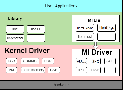
From top to bottom, the whole architecture is divided into application layer, software library layer, driver layer and hardware layer.
-
Application layer: Linux applications developed by users, running in Linux user space;
-
MI user interface layer: User‑space interfaces of MI SDK. Applications access MI drivers through this layer to operate the hardware;
-
Driver layer: Concrete implementation of MI drivers;
-
Hardware layer: Hardware of the Sgs platform.
2. Module Introduction
| Abbr | Full name | Responsibility |
|---|---|---|
| SYS | System | Implements MI system initialization, memory management, and data‑flow management between modules |
| SCL | Scaler | Provides scaling/cropping/format‑conversion functions |
| VDISP | Virtual Display | Software mosaic/pseudo display |
| DISP | Display Engine | Performs hardware composition for images output by VDEC/SCL units and, together with AO audio, encodes them into HDMI/VGA/CVBS output signals |
| VDEC | Video Decoder | Decodes H.264/H.265 video streams, providing channel management, stream input, and output image crop/scale control |
| VENC | Video Encoder | H.264/H.265/Motion JPEG encoder |
| JPD | JPEG Decoder | JPEG decoder module that provides decoding channel creation, stream input and decoding control |
| AI | Audio Input Interface | Audio input capture unit |
| AO | Audio Output Interface | Audio output |
| RGN | Region | Region management module, used to mask/overlay SCL data |
| IVE | Intelligent Video Engine | Provides basic operators used in intelligent vision algorithms |
| VDF | Video Detection Framework | Middleware framework integrating video detection libraries such as MD/OD/VG |
| IPU | Intelligent Process Unit | Intelligent processor, accelerates AI model inference |
| IPU_CASCADE | IPU Cascade | Cascade interface for multi‑IPU parallel inference of large models, accelerating offline LLM cascade models across local and remote IPU boards |
| GFX | Graphic Engine | Hardware graphics engine for fast 2D drawing and bitmap blit operations with scaling, rotation, mirroring, format conversion, alpha blending and Color Key |
| FB | Framebuffer | Graphics‑layer driver based on Linux framebuffer, managing display buffers and overlaying graphics layers onto video paths |
Dependencies between modules can be viewed in the kernel via the lsmod command.
mi_venc,mi_scldepend onmi_rgn.mi_ai,mi_aodepend onmi_aio.mi_debug,mi_venc,mi_vdf,mi_ao,mi_ai,mi_ive,mi_scl,mi_rgn,mi_ipudepend onmi_sys.-
mi_sys,mi_debug,mi_venc,mi_vdf,mi_ao,mi_ai,mi_ive,mi_scl,mi_rgn,mi_ipu,mi_jpd,mi_fb,mi_gfxdepend onmi_common. -
mi_vdecdepends on bothmi_sysandmi_common. -
The IPU_CASCADE interface is built on top of the
mi_ipumodule; in practice it reusesmi_ipuand its basic dependencies.
3. SDK Directory Structure
3.1. Detailed SDK directory structure
For the generic SDK directory explanation, please refer to SDK Directory Guide.
3.2. SDK and kernel decoupling notes
There is inevitably some coupling between SDK and kernel. When customers reconfigure and trim the kernel by themselves, they may need Sgs to re‑release SDK ko modules.
To address this, the SDK parts that depend on kernel source code are open‑sourced into sdk/linux. When customers reconfigure/trim the kernel, they can rebuild the SDK ko modules themselves.
After modifying the kernel, you can rebuild ko modules as follows (make sure the toolchain environment is set first):
Full rebuild:
    cd project
    make clean ; make image -j32
Fast rebuild:
-
Configure the following necessary paths:
export PROJ_DIR=/home/xxx/project    # project root directory
export KDIR=/home/xxx/kernel         # kernel root directory
Typically,
PROJ_DIRis the path where the project tree resides, andKDIRis where the kernel sources reside. -
Build & package:
cd sdk/linux make clean ; make all -j32 make install -j32 cd ../../project make image-fast -j32 -
Build a single
mi_xxx.ko(takingmi_ai.koas an example):cd sdk/linux make ai -j32 -
Ignore certain modules when running
make all:Set the variable
FILTER_OUT_MODULESbefore building.
If, for some reason, mi_shadow.ko cannot or should not be built, you can set:
export FILTER_OUT_MODULES=shadow
If you want to ignore multiple modules, separate them with spaces:
export FILTER_OUT_MODULES="shadow ipu"
4. menuconfig Configuration System
menuconfig is a graphical configuration interface that provides comprehensive SDK configuration options. You can launch it with the make menuconfig command.
4.1. Main configuration categories
menuconfig mainly includes the following configuration categories:
- Chip series name – Configure the specific chip family/model
- Product type – Select product forms such as ipc, usbcam, nvr, dispcam
- Development board – Configure board model/name and related hardware/software settings
- Toolchain configuration – Set compiler toolchain, architecture and version
- U-Boot configuration – Configure U-Boot build parameters and binary
- Linux kernel configuration – Set kernel version and kernel config file
- Image packaging configuration – Configure partition layout, file system and other packaging options
- Customer feature configuration – Configure MI debug, power management and other customer‑specific features
- DRAM_LAYOUT configuration – Adjust memory size and layout of runtime modules
- SDK configuration – Configure build options for modules within the SDK
4.2. Configuration flow
- Run
make menuconfigto start the configuration UI; - Select configuration options according to your requirements;
- Save the configuration and exit;
-
Run
make image -j32to build.For detailed configuration instructions, please refer to alkaid_defconfigconfiguration guide.
5. Memory Management
5.1. Memory allocation
For details, please refer to memory layout description.
6. Basic Concepts
-
Data flow: Each MI module can be regarded as a pure data‑processing unit. Data flow scheduling is unified inside MI SYS. The input data flow represents the input data of the unit, and the output data flow represents the data produced after processing.
-
Control flow: The process in which the APP configures parameters for each MI module’s data processing, such as setting MI_VDEC decoding parameters, starting/stopping MI_VDEC channels, and configuring resolution/format of MI_VDEC output ports.
-
Channel:
For MI modules that need to process or output streams, a channel represents the time‑multiplexed context for one stream of that module and the associated control‑flow settings.
For modules that support time‑multiplexing, such as MI_VDEC, MI_DIVP, MI_DISP, multiple channels are supported.
-
Port:
Ports are divided into two types: input port and output port. The input port is where a channel receives its input data flow, and the output port is where the channel outputs its data flow.
A channel can have multiple input ports and multiple output ports.
7. Root File System
Please refer to system partition guide.
8. Boot Flow
Please refer to boot flow description.