PCIE DebugSOP Manual
REVISION HISTORY
| Revision No. | Description |
Date |
|---|---|---|
| 1.0 | 05/14/2026 |
1. PCIe Link Training Failure (Link Not Up)
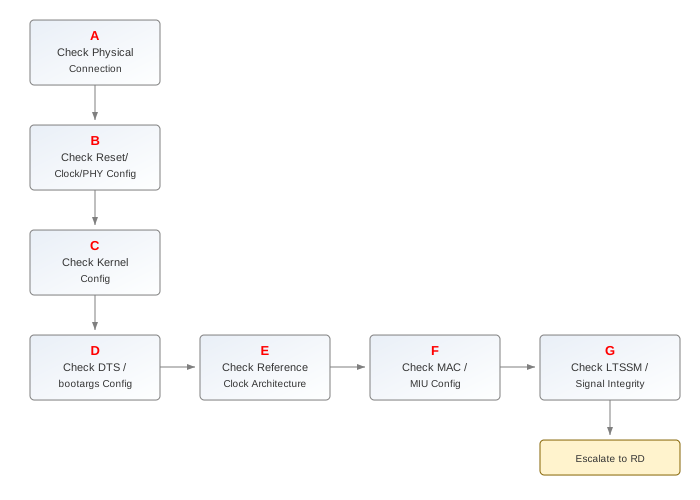
| Step | Method | Exit Conditions | Next Step | Information to Provide to FAE | Related FAQs |
|---|---|---|---|---|---|
| A | 1. Check the physical connection between RC and EP. Verify the PCIe cable/riser is properly seated and the connector pins are not damaged. 2. Use a multimeter to confirm the power supply to the PCIe slot is within spec (3.3V/12V as applicable). 3. Confirm the cable type matches the PCIe port configuration (e.g., same port type on both ends for dual EVB cascade). |
Exit Condition 1: 1. Physical connection is abnormal (cable damaged, loose connector, or power out of spec) 2.>Hardware connection issue Exit Condition 2: Physical connection is normal> No issue |
Exit Condition 1: > Process ends Exit Condition 2: > B |
Exit Condition 1: ==> Seek hardware assistance |
|
| B | 1. Check chiptop SW RESET register: bank 0x101E, offset 0x1F. PCIE0: bit14, PCIE1: bit15. The reset must be released for PCIe to function. 2. Check AXI SLV CLK configuration: CLKGEN2 bank 0x103F, confirm the clock is enabled. 3. Check PHY configuration: confirm PHY registers are set correctly according to ASIC requirements. For PCIE0 LAN1, note that the PHY is shared with USB3.0 Port2. |
Exit Condition 1: 1. SW RESET is not released or AXI SLV CLK is not enabled 2.>Clock/Reset configuration error Exit Condition 2: 1. PHY configuration does not match the specification (ASIC vs FPGA vs PZ1) >PHY configuration issue Exit Condition 3: All basic configurations are normal==> No issue |
Exit Condition 1: > Process ends Exit Condition 2: > Process ends Exit Condition 3: ==> C |
Exit Condition 1: > Check reset and clock settings in software Exit Condition 2: > Dump PHY registers for analysis |
|
| C | 1. Check the kernel config: confirm CONFIG_SGS_PCIE_HOST is enabled for RC mode, CONFIG_SGS_PCIE_EP is enabled for EP mode. 2. For dual EVB cascade testing, both RC and EP drivers may be needed depending on the test scenario. 3. Confirm CONFIG_SGS_PCI_ENDPOINT_TEST and CONFIG_SGS_PCI_EPF_TEST are enabled for pcitest-based validation. |
Exit Condition 1: 1. Required kernel configs are not enabled >Kernel config issue Exit Condition 2: Kernel config is normal> No issue |
Exit Condition 1: > Process ends Exit Condition 2: > D |
Exit Condition 1: ==> Enable the missing kernel configs and rebuild |
|
| D | 1. Check DTS configuration for PCIe nodes (PCIE0/PCIE1). The compatible property has three options: - sgs,dw-pcie: Force RC mode - sgs,dw-pcie-ep: Force EP mode - sgs,dw-pcie-earlyparam: Mode determined by U-Boot bootargs env 2. If using sgs-dw-pcie-earlyparam, verify bootargs contains correct mode settings (e.g., pcie0=rc, pcie1=ep for dual EVB cascade). 3. For dual EVB cascade: one board should be configured as RC, the other as EP. 4. For single EVB dual-port cascade: use a long cable to connect the two PCIe ports, configure one as RC and the other as EP (e.g., pcie0=rc pcie1=ep or pcie0=ep pcie1=rc). |
Exit Condition 1: 1. DTS compatible is not correctly configured >DTS configuration error Exit Condition 2: 1. bootargs mode configuration does not match the physical connection >bootargs configuration error Exit Condition 3: Configuration is normal==> No issue |
Exit Condition 1: > Process ends Exit Condition 2: > Process ends Exit Condition 3: ==> E |
Exit Condition 1: > Correct the DTS compatible property Exit Condition 2: > Correct the bootargs env setting |
|
| E | 1. Check the Reference Clock architecture configuration: - Common Clock (CC): RC and EP share the same 100MHz reference clock source. This is the most common and recommended setup. - Independent Refclk (IR): RC and EP use independent clock sources. SOC internal sources include MPLL (432MHz) and GMAC PLL (100MHz). External source from on-board clock generator chip is also available. 2. For IR mode, verify bootargs clk parameter configuration: - No clk parameter: default uses MPLL 432MHz - With clk parameter: can select GMAC 100MHz or external clock chip 3. For CC mode, verify the clock line connection and any required board rework (e.g., disconnect on-board clock chip on the clock-receiving board). 4. Note: SSC (Spread Spectrum Clocking) can only be applied to Common Clock architecture. |
Exit Condition 1: 1. Reference clock architecture mismatch between RC and EP >Clock architecture configuration error Exit Condition 2: 1. For CC mode, board rework not done (clock chip not disconnected on receiving board) >Board rework required Exit Condition 3: 1. Clock configuration is normal but link still fails ==>Proceed to next step |
Exit Condition 1: > Process ends Exit Condition 2: > Process ends Exit Condition 3: ==> F |
Exit Condition 1: > Verify clock configuration in bootargs and DTS Exit Condition 2: > Hardware rework needed |
|
| F | 1. Check MAC configuration: - reg_slv_wstrb_mask must be set to 0xFFFF - reg_enable_axi_mstr_optimize: used to optimize PCIe access to MIU - reg_pcie_msi_mask_irq: controls whether MSI interrupts are visible to CPU - reg_sup_phy_bifurcation_sel_mac: controls PCIE0 LAN1 switching 2. Check reg_sel_pcie_axi_mstr_to_imi: only valid for PCIE1, used for PCIe boot accessing IMI. 3. Check MIU back-pressure configuration: if not configured, DMA data will be corrupted and DMA interrupt done status may not be received. 4. Check DB_RO_WR_EN: some read-only registers can be written after enabling this. For example, PCIE0 MISC_CONTROL1_OFF bit0 is DBI_RO_WR_EN; without enabling it, vendor ID and device ID cannot be written. |
Exit Condition 1: 1. MAC register configuration is incorrect >MAC configuration error Exit Condition 2: 1. MIU back-pressure not configured >MIU configuration missing Exit Condition 3: All configurations are normal==> No issue |
Exit Condition 1: > Process ends Exit Condition 2: > Process ends Exit Condition 3: ==> G |
Exit Condition 1: > Dump MAC registers for analysis Exit Condition 2: > Enable MIU back-pressure configuration |
|
| G | 1. Check the PCIe log during boot to confirm LTSSM state transitions. 2. Verify both RC and EP have enabled ltssm_enable for link training. 3. If link training still fails after all above checks, use LA/oscilloscope to capture the PCIe TX/RX signal waveforms and check signal integrity. 4. Consider cross-validation: swap RC/EP roles, try different PCIe ports, or test with different cables/boards. |
Exit Condition 1: 1. LTSSM fails to reach L0 state >Signal integrity or PHY issue Exit Condition 2: 1. LTSSM reaches L0 but link is unstable >Possible signal quality issue Exit Condition 3: 1. Link is up after cross-validation ==>Specific hardware issue on the failing board |
Exit Condition 1: > Process ends, provide waveform data to RD Exit Condition 2: > Process ends, adjust PHY parameters Exit Condition 3: ==> Process ends |
Exit Condition ½: 1. Provide serial log including PCIe initialization 2. Provide waveform capture of TX/RX signals 3. Dump RIU registers for PCIE banks |
2. PCIe EP Enumeration Failure (RC Cannot Detect EP)
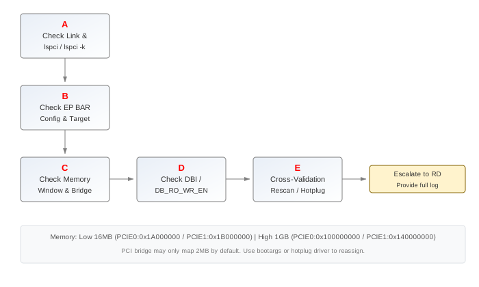
| Step | Method | Exit Conditions | Next Step | Information to Provide to FAE | Related FAQs |
|---|---|---|---|---|---|
| A | 1. Confirm the PCIe link is up by checking boot log. Look for messages indicating "Link Up". 2. Execute lspci on the RC side to see if the EP device is listed.3. Execute lspci -k to check detailed device information including vendor ID, device ID, and kernel driver binding. |
Exit Condition 1: 1. Link is not up, no PCIe device found >Refer to Issue 1: Link Training Failure Exit Condition 2: 1. Link is up but EP not enumerated >Proceed to next step |
Exit Condition 1: > Go to Issue 1 Exit Condition 2: > B |
||
| B | 1. Check EP-side BAR configuration. EP BAR0 can use Target0 or Target1 (default is Target0). Target0 allows RC to access EP's DMA/ATU/ELBI registers. 2. Verify EP BAR size configuration. BAR0 default is 4MB because DMA(4K)+ATU(4K)+RIU(4MB)=4.8MB, covering RIU up to bank 0x1AEF. 3. RC init will reset BAR1 because the default 1GB BAR1 would exhaust the PCIe memory space. 4. Check whether the target register (e.g., bank 0x1AB4 offset 7 bit0) is correctly configured for Target0/Target1 selection. Only BAR0 target selection is effective; other BARs can only use Target1. |
Exit Condition 1: 1. BAR configuration is incorrect or BAR size mismatch >BAR configuration error Exit Condition 2: BAR configuration is normal> No issue |
Exit Condition 1: > Correct BAR configuration Exit Condition 2: > C |
Exit Condition 1: ==> Check target register settings and BAR size |
|
| C | 1. Check RC-side memory window configuration in DTSI. mHera has two address spaces: - Low 16MB: PCIE0 at 0x1A000000, PCIE1 at 0x1B000000 - High 1GB: PCIE0 at 0x100000000, PCIE1 at 0x140000000 2. Kernel defaults to using the high 1GB space. If using low 16MB space, modify DTSI accordingly. 3. Note: 16MB may not be sufficient to allocate all RC and EP BARs. RC BAR0 is 4MB, EP BAR0 is 4MB, plus other EP BARs with size alignment requirements. 4. Check PCI bridge resource allocation. Sometimes the bridge only maps 2MB by default. Can set bootargs env to force a larger window, or enable PCIe hotplug driver to automatically reassign memory space based on EP BAR size. |
Exit Condition 1: 1. Memory window size is insufficient for BAR allocation >Memory space exhaustion Exit Condition 2: 1. PCI bridge resource mapping is too small (e.g., only 2MB) >Bridge resource mapping issue Exit Condition 3: Memory configuration is normal==> No issue |
Exit Condition 1: > Increase memory window or reduce BAR sizes Exit Condition 2: > Adjust bootargs or enable hotplug driver Exit Condition 3: ==> D |
Exit Condition 1: > Provide DTSI configuration and BAR size requirements Exit Condition 2: > Provide bootargs and lspci output |
|
| D | 1. Check DBI access configuration. Verify DBI read/write is functioning correctly. 2. Verify DB_RO_WR_EN is enabled for writing read-only registers. Without it, vendor ID and device ID writes will not take effect. 3. Check PCIE0 MISC_CONTROL1_OFF bit0 (DBI_RO_WR_EN). 4. Confirm EP-side driver is loaded and initialized correctly. Check dmesg for EP driver initialization logs. |
Exit Condition 1: 1. DBI access is not working >DBI configuration issue Exit Condition 2: 1. Vendor/Device ID not properly configured >DB_RO_WR_EN not enabled Exit Condition 3: All checks pass==> No issue |
Exit Condition 1: > Process ends Exit Condition 2: > Enable DB_RO_WR_EN Exit Condition 3: ==> E |
Exit Condition 1: ==> Dump DBI registers for analysis |
|
| E | 1. Perform cross-validation: swap RC/EP roles between the two boards/ports. 2. Try manual rescan: echo 1 > /sys/bus/pci/rescan3. Enable CONFIG_SGS_PCIE_HOTPLUG for automatic EP detection and BAR reassignment after link up. |
Exit Condition 1: 1. EP enumerated after rescan/hotplug >Enumeration timing issue Exit Condition 2: 1. EP enumerated after role swap >Configuration issue on one side Exit Condition 3: Enumeration still fails ==> Escalate to RD |
Exit Condition 1: > Process ends Exit Condition 2: > Fix configuration on the failing side Exit Condition 3: ==> Process ends |
Exit Condition 3: 1. Provide complete boot serial log 2. Provide lspci output 3. Provide DTSI configuration |
3. PCIe DMA Data Transfer Failure
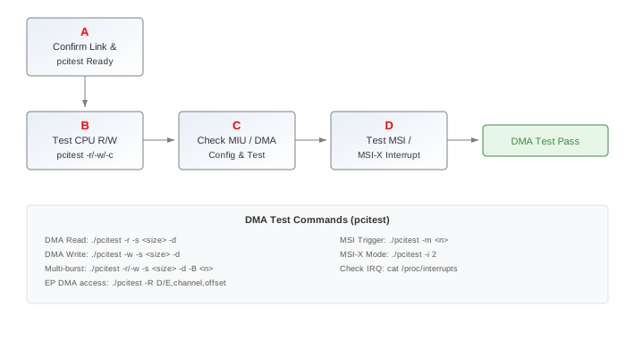
| Step | Method | Exit Conditions | Next Step | Information to Provide to FAE | Related FAQs |
|---|---|---|---|---|---|
| A | 1. Confirm PCIe link is up and EP is enumerated successfully (refer to Issue 1 and Issue 2 if needed). 2. Check pcitest tool is compiled correctly: go to kernel/tools/pci/ and run make to generate pcitest binary. 3. pcitest runs on the RC side. RC sends commands through test BAR to instruct EP operations. 4. Verify CONFIG_SGS_PCI_ENDPOINT_TEST and CONFIG_SGS_PCI_EPF_TEST are enabled in kernel config. |
Exit Condition 1: 1. Link is not up or EP not enumerated >Refer to Issue ½ Exit Condition 2: 1. pcitest tool not available or kernel config missing >Tool/config issue Exit Condition 3: Prerequisites are met==> No issue |
Exit Condition 1: > Go to Issue 1 or 2 Exit Condition 2: > Build pcitest and enable configs Exit Condition 3: ==> B |
||
| B | 1. Test CPU-based read/write first: - Read (EP->RC): ./pcitest -r -s <size>- Write (RC->EP): ./pcitest -w -s <size>- Copy (RC->EP->RC): ./pcitest -c -s <size> (verifies PCIe path integrity)2. If CPU R/W works but DMA fails, the issue is DMA-specific. If CPU R/W also fails, check BAR and target configuration. |
Exit Condition 1: 1. CPU R/W fails >BAR or target configuration issue Exit Condition 2: 1. CPU R/W succeeds but DMA fails >DMA-specific issue Exit Condition 3: Both CPU R/W and DMA work==> Test other features |
Exit Condition 1: > Go to Issue 2 (BAR/target check) Exit Condition 2: > C Exit Condition 3: ==> D |
Exit Condition 1: ==> Check BAR0 target0 configuration and memory mapping |
|
| C | 1. Check MIU back-pressure configuration: without proper MIU back-pressure, DMA data will be corrupted and DMA interrupt done status may not be received. 2. Test DMA with various sizes and burst configurations: - Read (EP->RC) by DMA: ./pcitest -r -s <size> -d- Write (RC->EP) by DMA: ./pcitest -w -s <size> -d- Multi-burst read: ./pcitest -r -s <size> -d -B <burst_count>- Multi-burst write: ./pcitest -w -s <size> -d -B <burst_count>3. Check DMA channel configuration. RC can access EP DMA through Target0 using: ./pcitest -R D/E,channel,offset (D=read channel, E=write channel).4. Verify reg_enable_axi_mstr_optimize is enabled for optimizing PCIe MIU access. |
Exit Condition 1: 1. MIU back-pressure not configured >MIU configuration missing Exit Condition 2: 1. DMA works with single burst but fails with multi-burst >Burst configuration issue Exit Condition 3: 1. DMA data corruption observed >Signal integrity or MIU issue Exit Condition 4: DMA works correctly> No issue |
Exit Condition 1: > Enable MIU back-pressure Exit Condition 2: > Adjust burst parameters Exit Condition 3: > Check PHY signal quality Exit Condition 4: > D |
Exit Condition 3: 1. Provide DMA test log with data comparison 2. Dump MIU and DMA registers |
|
| D | 1. Test MSI interrupt functionality: cat /proc/interrupts to check MSI interrupt information.2. Trigger specific MSI interrupt: ./pcitest -m <msi_number>3. Test MSI-X: ./pcitest -i 2 to switch to MSI-X mode.4. Check reg_pcie_msi_mask_irq register: controls whether MSI interrupts are visible to CPU. 5. Verify EP DMA remote interrupt works (RC write EP DMA via Target0 and trigger remote interrupt). Note: MSI stop address, MSI data/SAR/DAR in test scripts may be hardcoded and need adjustment based on actual configuration. |
Exit Condition 1: 1. MSI/MSI-X interrupts not received >Interrupt configuration issue Exit Condition 2: 1. Interrupt test passes >Proceed to next feature test |
Exit Condition 1: > Check interrupt mask and configuration Exit Condition 2: > Process ends |
Exit Condition 1: 1. Provide /proc/interrupts output 2. Provide interrupt test log |
4. PCIe BAR and ELBI Access Issues
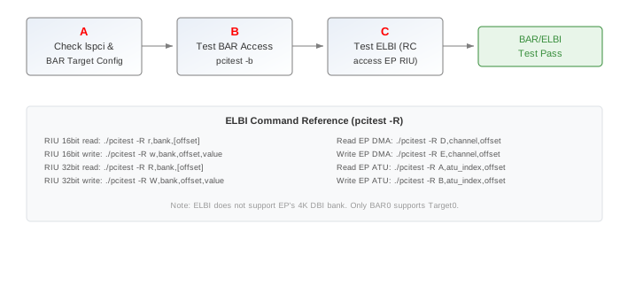
| Step | Method | Exit Conditions | Next Step | Information to Provide to FAE | Related FAQs |
|---|---|---|---|---|---|
| A | 1. Confirm PCIe link is up and EP is enumerated. Execute lspci -k to check device information.2. Identify which BAR is being accessed and its configuration: - EP BAR0: can use Target0 (default) or Target1. Target0 allows RC to access EP DMA/ATU/ELBI. - EP BAR1-BAR5: can only use Target1. - RC BAR0: default 4MB, RC BAR1 is reset by init to avoid exhausting memory space. 3. Verify the target selection register configuration (EP PCIE0: bank 0x1AB4 offset 7 bit0; EP PCIE1: bank 0x1AB4 offset 7 bit0). Only BAR0 target selection is effective. |
Exit Condition 1: 1. Target selection register is misconfigured (bit0 should be 0 for Target0) >Target configuration error Exit Condition 2: 1. BAR size too large causing memory allocation failure >BAR size issue Exit Condition 3: BAR configuration is normal==> No issue |
Exit Condition 1: > Correct target selection register Exit Condition 2: > Reduce BAR size Exit Condition 3: ==> B |
Exit Condition 1: ==> Dump target selection register |
|
| B | 1. Test BAR access using pcitest: - BAR test: ./pcitest -b (default tests BAR1-BAR5 since BAR0 uses Target0 for special purposes)2. If BAR test fails for specific BAR, check if the corresponding memory region is properly allocated. 3. For low 16MB address space users: verify BAR sizes fit within the available window. Consider reducing BAR sizes if 16MB is insufficient. |
Exit Condition 1: 1. BAR test passes for all tested BARs >BAR access normal Exit Condition 2: 1. Specific BAR test fails >BAR allocation or mapping issue |
Exit Condition 1: > C Exit Condition 2: > Check memory allocation and BAR mapping |
Exit Condition 2: 1. Provide lspci output with BAR info 2. Provide BAR test log |
|
| C | 1. Test ELBI (RC access EP RIU) functionality using pcitest: - ./pcitest -R r/w/R/W,bank,[offset]- r: 16-bit RIU read, w: 16-bit RIU write - R: 32-bit RIU read, W: 32-bit RIU write - Without offset: r/R reads the entire bank - Note: does not support accessing EP's 4K DBI bank 2. Example commands: - RC read EP bank 0x1004: ./pcitest -R r,0x1004- RC read EP bank 0x1004 offset 0: ./pcitest -R r,0x1004,0- RC 32-bit read EP bank 0x1AB0: ./pcitest -R R,0x1AB0 (log may interleave due to printk continuous)- RC 32-bit read EP bank 0x1AB0 offset 0: ./pcitest -R R,0x1AB0,0- RC write EP bank 0x1004 offset 0: ./pcitest -R w,0x1004,0,<value>3. Test RC access EP DMA: ./pcitest -R D/E,channel,offset (D=read DMA channel, E=write DMA channel).4. Test RC access EP ATU: ./pcitest -R A/B,atu_index,offset (A=read ATU index, B=write ATU bank). |
Exit Condition 1: 1. ELBI read/write works correctly >ELBI function normal Exit Condition 2: 1. ELBI access returns incorrect data >Target0 configuration or RIU mapping issue Exit Condition 3: 1. ELBI access fails completely ==>BAR0 Target0 not configured or link issue |
Exit Condition 1: > Process ends Exit Condition 2: > Verify target0 configuration and RIU mapping Exit Condition 3: ==> Go to Issue 1 |
Exit Condition ⅔: 1. Provide ELBI test commands and output 2. Dump target register configuration |
5. PCIe Hotplug and Link Stability Issues
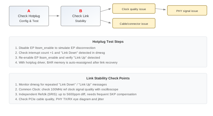
| Step | Method | Exit Conditions | Next Step | Information to Provide to FAE | Related FAQs |
|---|---|---|---|---|---|
| A | 1. Check if CONFIG_SGS_PCIE_HOTPLUG is enabled in kernel config. 2. With hotplug enabled, RC will automatically detect EP after link up and reassign BAR memory space without manual rescan. 3. Verify hotplug functionality by disabling EP ltssm_enable to simulate EP disconnection: check if interrupt count increases and "Link Down" is detected. 4. Re-enable EP ltssm_enable to verify "Link Up" is detected. |
Exit Condition 1: 1. Hotplug is not enabled >Enable kernel config Exit Condition 2: 1. Hotplug enabled but Link Down/Up not detected >Interrupt or ltssm configuration issue Exit Condition 3: 1. Hotplug works correctly ==>Function normal |
Exit Condition 1: > Enable hotplug config Exit Condition 2: > B Exit Condition 3: ==> Process ends |
Exit Condition 2: 1. Provide interrupt status 2. Check ltssm_enable register |
|
| B | 1. Check if the link is frequently going down and up. Monitor dmesg for repeated "Link Down" / "Link Up" messages.2. Verify the reference clock stability. For Common Clock architecture, check clock signal quality with oscilloscope. 3. For Independent Refclk architecture, verify both sides have stable clock sources. SRIS mode allows up to 5600ppm frequency difference, which requires frequent SKP Ordered Set compensation and may affect stability. 4. Check PCIe cable quality and connection stability. 5. Verify PHY signal integrity. Check for excessive jitter, insufficient eye width/height on TX/RX signals. |
Exit Condition 1: 1. Link instability caused by clock signal quality >Clock quality issue Exit Condition 2: 1. Link instability caused by cable/connection >Physical connection issue Exit Condition 3: 1. Link instability caused by PHY signal quality >Signal integrity issue Exit Condition 4: 1. Link is stable after fixing >Issue resolved |
Exit Condition 1: > Improve clock signal quality or switch clock architecture Exit Condition 2: > Replace cable or fix connection Exit Condition 3: > Adjust PHY parameters or check board layout Exit Condition 4: > Process ends |
Exit Condition ⅓: 1. Provide dmesg log showing link instability pattern 2. Provide clock/signal waveform captures 3. Provide PHY register dumps |
6. Appendix
6.1 mHera PCIe Address Space
mHera provides two PCIe CPU-accessible address spaces:
| Address Space | PCIE0 | PCIE1 | Size |
|---|---|---|---|
| Low Address | 0x1A000000 | 0x1B000000 | 16MB |
| High Address | 0x100000000 | 0x140000000 | 1GB |
Kernel defaults to using the high 1GB address space. The low 16MB space may be insufficient for BAR allocation due to size alignment requirements.
6.2 DTSI Compatible Configuration
The PCIe node compatible property supports three options:
| Compatible | Description | Usage |
|---|---|---|
| sgs,dw-pcie | Force RC mode | Fixed RC device |
| sgs,dw-pcie-ep | Force EP mode | Fixed EP device |
| sgs-dw-pcie-earlyparam | Mode from bootargs | Flexible, recommended for debugging |
For sgs-dw-pcie-earlyparam, set mode via bootargs env:
- Dual EVB cascade:
pcie0=rc pcie1=ep(one board) andpcie0=ep pcie1=rc(other board) - Single EVB dual-port:
pcie0=rc pcie1=eporpcie0=ep pcie1=rc
6.3 Reference Clock Architecture
| Architecture | Description | SSC Support | Notes |
|---|---|---|---|
| Common Clock (CC) | RC and EP share same 100MHz ref clock | Supported | Most common, simple design, good signal quality |
| Independent Refclk (IR) - SRNS | Separate clocks, no SSC | Not supported | Uses SKP Ordered Sets for compensation |
| Independent Refclk (IR) - SRIS | Separate clocks, with SSC | Supported | Up to 5600ppm difference, higher latency |
| Data Clocked | Recover clock from data stream | Not supported | Not supported on mHera, not recommended |
SOC internal clock sources for IR mode:
- MPLL: 432MHz (default, no clk parameter in bootargs)
- GMAC PLL: 100MHz (set via bootargs clk parameter)
- External: from on-board clock generator chip (set via bootargs clk parameter)
6.4 Key Register Reference
| Register | Bank | Offset | Bits | Description |
|---|---|---|---|---|
| SW RESET | 0x101E | 0x1F | bit14 (PCIE0), bit15 (PCIE1) | Release reset for PCIe operation |
| AXI SLV CLK | CLKGEN2 (0x103F) | - | - | AXI slave clock enable |
| MISC_CONTROL1_OFF (DBI_RO_WR_EN) | PCIE0 DBI | - | bit0 | Enable writing to read-only registers |
| reg_slv_wstrb_mask | MAC | - | - | Must be set to 0xFFFF |
| Target Selection | 0x1AB4 | 0x7 | bit0 | BAR0 target: 0=Target0, 1=Target1 |
6.5 pcitest Command Reference
pcitest tool is located at kernel/tools/pci/. Compile with make in that directory. pcitest runs on the RC side.
| Command | Description |
|---|---|
| ./pcitest -r -s \<size> | CPU read (EP->RC) |
| ./pcitest -w -s \<size> | CPU write (RC->EP) |
| ./pcitest -c -s \<size> | CPU copy (RC->EP->RC) |
| ./pcitest -r -s \<size> -d | DMA read (EP->RC) |
| ./pcitest -w -s \<size> -d | DMA write (RC->EP) |
| ./pcitest -r -s \<size> -d -B \<n> | DMA multi-burst read |
| ./pcitest -w -s \<size> -d -B \<n> | DMA multi-burst write |
| ./pcitest -m \<n> | Trigger MSI interrupt n |
| ./pcitest -i 2 | Switch to MSI-X mode |
| ./pcitest -b | BAR test (BAR1-BAR5) |
| ./pcitest -R r/w/R/W,bank,[offset] | ELBI: RIU read/write (r=16bit read, w=16bit write, R=32bit read, W=32bit write) |
| ./pcitest -R D/E,channel,offset | RC access EP DMA (D=read, E=write) |
| ./pcitest -R A/B,atu_index,offset | RC access EP ATU (A=read, B=write) |