Pspi_DebugSop
REVISION HISTORY
| Revision No. | Description |
Date |
|---|---|---|
| 1.00 | 2024.12.13 |
1. Introduction
This document aims to introduce how to conduct preliminary troubleshooting when encountering MI PSPI-related issues, quickly locate the problem, and determine what information needs to be provided to RD for analysis if it is a Sgs SDK issue.
2. Panel-related Issues
| BUS | MODULE BANK | BDMA BANK | PSPI CLOCK BIT |
|---|---|---|---|
| PSPI0 | 0x1670 | 0x100B | 0x1038 0x30 BIT0 |
| PSPI1 | 0x1676 | 0x100C | 0x1038 0x30 BIT8 |
2.1 No Display on Panel (Black Screen)
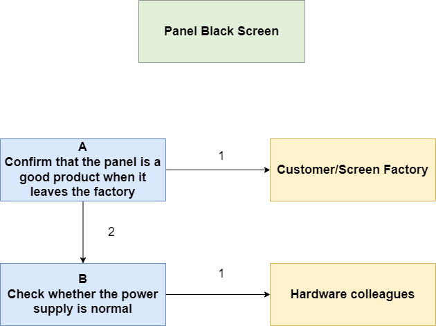
After the panel hardware is connected, it remains in a black screen state. Debug process:
| Process | Confirmation Method | Exit Conditions | Next Step | Information to Provide | Related FAQs |
|---|---|---|---|---|---|
| A | Cross-test to confirm if the panel is functioning normally | Exit Condition 1: Panel is abnormal; Exit Condition 2: Panel is normal | Exit Condition 1: Please seek assistance from the customer/screen factory; Exit Condition 2: B | ||
| B | Check if the power supply voltage at the board end meets the panel requirements, especially pay attention to insufficient voltage on data pin, which may prevent the panel from receiving data | Exit Condition 1: Power supply voltage meets requirements; | Exit Condition 1: Please seek assistance from hardware colleagues; |
2.2 Panel Cannot Display Any RGB Images
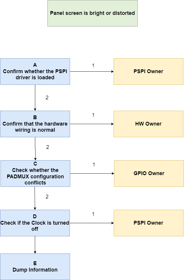
After running the pspi ut demo, the panel only shows a bright screen or is in a garbled state. Debug process:
| Process | Confirmation Method | Exit Conditions | Next Step | Information to Provide | Related FAQs |
|---|---|---|---|---|---|
| A | Confirm if the PSPI driver is loaded: 1. Compile ko, lsmod -> can see mi_pspi info 2. Build in, check the value of module bank 0x2, if all are 0, it indicates the driver is not loaded | Exit Condition 1: PSPI driver not loaded; Exit Condition 2: PSPI driver loaded | Exit Condition 1: Please seek assistance from the pspi owner; Exit Condition 2: B | Exit Condition 1: Initialization log and bank information | |
| B | Confirm hardware wiring: 1. Check the tmux table, connect the used PINs to LA or oscilloscope 2. Operate GPIO registers to pull high and low, observe if the PINs change synchronously | Exit Condition 1: Pulling GPIO high and low, PINs do not change; Exit Condition 2: Wiring is normal | Exit Condition 1: Please seek assistance from hardware colleagues; Exit Condition 2: C | ||
| C | Confirm PADMUX configuration: 1. Check the tmux table, confirm if the PADMUX multiplexing relationship is correct | Exit Condition 1: PSIPI MODE not configured or occupied by a higher priority MODE; Exit Condition 2: PADMUX configuration is normal | Exit Condition 1: Correct the configuration yourself or seek assistance from the gpio owner; Exit Condition 2: D | ||
| D | Confirm if the pspi clock is turned off: 1. CLOCK BIT = 1, indicating the clock is abnormally turned off | Exit Condition 1: Clock is off; Exit Condition 2: Clock is normal | Exit Condition 1: Please seek assistance from the pspi owner; Exit Condition 2: E | ||
| E | Provide debug information: Provide module bank, bdma bank, and log information to the pspi owner |
2.3 Panel Displays a Single Color or Screen Tearing
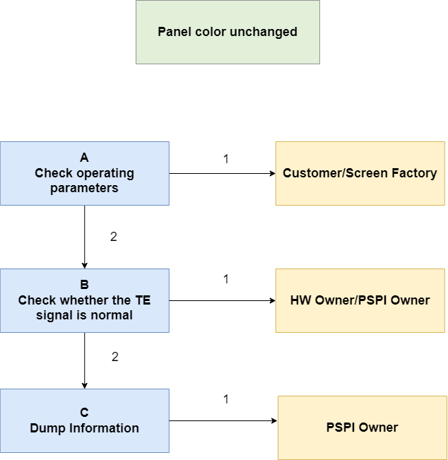
After running the pspi ut demo, the panel only displays one color and cannot continuously refresh RGB. Debug process:
| Process | Confirmation Method | Exit Conditions | Next Step | Information to Provide | Related FAQs |
|---|---|---|---|---|---|
| A | Check running parameters: 1. Check if the dataline meets the panel requirements 2. Check if the communication frequency meets the panel requirements | Exit Condition 1: Parameters are abnormal; Exit Condition 2: Parameters are normal | Exit Condition 1: Please confirm parameters with the customer or screen factory; Exit Condition 2: B | ||
| B | Confirm TE signal: 1. Connect TE/DATA and other PINs to LA or oscilloscope 2. Check if the TE signal is continuously changing 3. Generally, TE signal is low level during data transmission, and one signal cycle transmits one frame of data | Exit Condition 1: TE signal is abnormal; Exit Condition 2: TE signal is normal | Exit Condition 1: Please seek assistance from hw/pspi owner; Exit Condition 2: C | ||
| C | Provide debug information: Provide module bank, bdma bank, and log information to the pspi owner |
3. Sensor-related Issues
| BUS | MODULE BANK | BDMA BANK | PSPI CLOCK BIT | MCLOCK BIT |
|---|---|---|---|---|
| PSPI0 | 0x1670 | 0x100B | 0x1038 0x30 BIT0 | 0x1038 0x62 BIT8 |
| PSPI1 | 0x1676 | 0x100C | 0x1038 0x30 BIT8 | 0x1038 0x62 BIT8 |
3.1 No Image Generation from Sensor
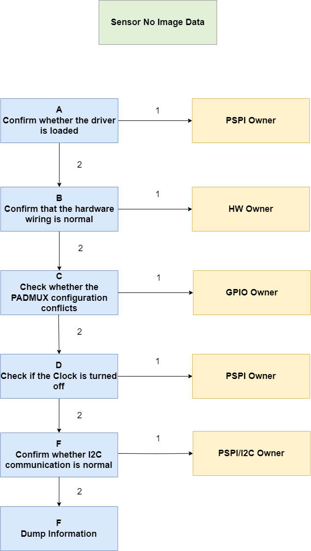
After running the pspi ut demo, no image data from the sensor is generated. Debug process:
| Process | Confirmation Method | Exit Conditions | Next Step | Information to Provide | Related FAQs |
|---|---|---|---|---|---|
| A | Confirm if the PSPI and Sensor drivers are loaded: lsmod -> can see the info of mi_pspi and sensor ko, such as drv_pspi_bf3901, bf3901 is the sensor model, please pay attention to the correct binding of the sensor | Exit Condition 1: PSPI driver not loaded; Exit Condition 2: Sensor driver not loaded; Exit Condition 3: Both drivers are loaded | Exit Condition 1: Please seek assistance from the pspi owner; Exit Condition 2: Please seek assistance from the pspi owner Exit Condition 3: B | ||
| B | Confirm hardware wiring: 1. Check the tmux table, connect the used PINs to LA or oscilloscope 2. Operate GPIO registers to pull high and low, observe if the PINs change synchronously | Exit Condition 1: Pulling GPIO high and low, PINs do not change; Exit Condition 2: Wiring is normal | Exit Condition 1: Please seek assistance from hardware colleagues; Exit Condition 2: C | ||
| C | Confirm PADMUX configuration: 1. Check the tmux table, confirm if the PADMUX multiplexing relationship is correct | Exit Condition 1: PSIPI MODE and I2C MODE not configured or occupied by a higher priority MODE; Exit Condition 2: PADMUX configuration is normal | Exit Condition 1: Correct the configuration yourself or seek assistance from the gpio owner; Exit Condition 2: D | ||
| D | Confirm if the pspi clock is turned off: 1. PSPI CLOCK BIT = 1, indicating the clock is abnormally turned off 2. MCLOCK BIT = 1, indicating mclock is abnormally turned off | Exit Condition 1: Clock is off; Exit Condition 2: Clock is normal | Exit Condition 1: Please seek assistance from the pspi owner; Exit Condition 2: E | ||
| E | Confirm if I2C communication is normal: 1. Connect SCL and SDA to LA or oscilloscope 2. Check I2C timing, whether it executes according to the initialization command, and if there is any nack signal | Exit Condition 1: I2C communication is abnormal; Exit Condition 2: I2C communication is normal | Exit Condition 1: Please seek assistance from the i2c owner; Exit Condition 2: F | ||
| F | Provide debug information: Provide module bank, bdma bank, and log information to the pspi owner |