Audio User Guide
REVISION HISTORY
| Revision No. | Description |
Date |
|---|---|---|
| 1.0 | 11/13/2024 |
Device Tree Configuration
-
I2S tdm configuration
Property name Description Value range i2s-rx0-tdm-ws-pgm TDM programmable mode 0: OFF
1: ONi2s-tx0-tdm-ws-pgm TDM programmable mode 0: OFF
1: ONi2s-rx0-tdm-ws-width Configure the width of tdm WCK 0~31 (width = value + 1) i2s-tx0-tdm-ws-width Configure the width of tdm WCK 0~31 (width = value + 1) Example:
i2s-rx0-tdm-ws-pgm = <0>;
i2s-rx0-tdm-ws-width = <0>;
i2s-tx0-tdm-ws-pgm = <1>;
i2s-tx0-tdm-ws-width = <0xf>;
If the pgm:width attribute is not enabled, the WCK duty cycle is fixed at 50%.
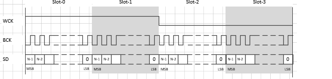
Open pgm: At this time, the width attribute takes effect, and the WCK width is (width+1)*bclk
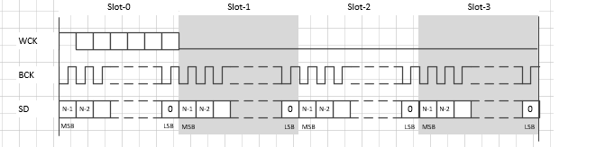
-
I2S wck flip
Property name Description Value range i2s-rx0-tdm-ws-inv I2S wck inversion 0: Do not invert
1: Inverti2s-tx0-tdm-ws-inv I2S wck inversion 0: Do not invert
1: InvertNo inversion:
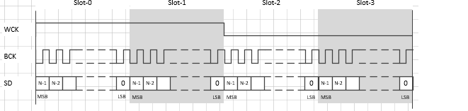
Inversion:
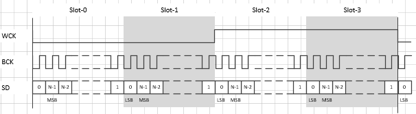
-
I2S rx-ch-swap
Property name Description Value range i2s-rx0-tdm-ch-swap Configure rx i2s channel swap See details below Each bit is set to 1 to turn it on, and 0 to turn it off. [0] : 0<-->2, 1<-->3, 4<-->6, 5<-->7 8<-->10, 9<-->11, 12<-->14, 13<-->15 [1] : 0<-->4, 1<-->5, 2<-->6, 3<-->7 8<-->12, 9<-->13, 10<-->14, 11<-->15 [2] : 0<-->8, 1<-->9, 2<-->10, 3<-->11 4<-->12, 5<-->13, 6<-->14, 7<-->15 [3]: 0: L at slot 0/2/4/6/8/10/12/14 R at slot 1/3/5/7/9/11/13/15 1: L at slot 0/1/2/3/4/5/6/7 R at slot 8/9/10/11/12/13/14/15Example:
i2s-rx-tdm-ch-swap = <0 0 0 0>; -
I2S tx-ch-swap
Property name Description Value range i2s-tx0-tdm-ch-swap Configure tx i2s channel swap See details below Each bit is set to 1 to turn it on, and 0 to turn it off. [0] : 0<-->2, 1<-->3, 4<-->6, 5<-->7 8<-->10, 9<-->11, 12<-->14, 13<-->15 [1] : 0<-->4, 1<-->5, 2<-->6, 3<-->7 8<-->12, 9<-->13, 10<-->14, 11<-->15 [2] : 0<-->8, 1<-->9, 2<-->10, 3<-->11 4<-->12, 5<-->13, 6<-->14, 7<-->15 [3]: 0: L at slot 0/2/4/6/8/10/12/14 R at slot 1/3/5/7/9/11/13/15 1: L at slot 0/1/2/3/4/5/6/7 R at slot 8/9/10/11/12/13/14/15Example:
i2s-tx-tdm-ch-swap = <0 0 0 0>; -
I2S tx valid channel
Property name Description Value range i2s-tx-tdm-active-slot Configure I2S tx active channel 0x00 ~ 0xFF (bit0->slot0, bit1->slot1, ... ) -
High pass filter
Property name Description Value range hpf-adc1-level High pass filter level < switch value >
switch:
0: disable hpf
1: enable hpf
value: 0~1500 cutoff frequencyhpf-dmic-level High pass filter level < switch value >
switch:
0: disable hpf
1: enable hpf
value: 0~1500 cutoff frequencyExample:
hpf-adc1-level = <1 20>; // Enable the high pass filter cutoff frequency of adc1 to 20hz
hpf-dmic-level = <1 20>; // Enable the high pass filter cutoff frequency of dmic to 20hz
Detailed description of the cutoff frequency parameters:
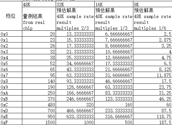
The actual cutoff frequency parameters of the HPF high-pass filter are different for different sampling rates:
The supported cutoff frequencies at 48K sampling rate are:
    20hz 23hz 26hz 32hz 38hz 52hz 65hz 95hz 140hz 190hz 250hz 370hz 480hz 700hz 980hz 1500hz
The supported cutoff frequencies at 32K sampling rate are:
    13hz 15hz 17hz 21hz 25hz 34hz 43hz 63hz 93hz 126hz 166hz 246hz 320hz 466hz 633hz 1000hz
The supported cutoff frequencies at 16K sampling rate are:
    6hz 7hz 8hz 10hz 12hz 17hz 21hz 31hz 46hz 63hz 83hz 123hz 160hz 233hz
    316hz 500hz
The supported cutoff frequencies at 8K sampling rate are:
    3hz 4hz 5hz 6hz 8hz 10hz 15hz 23hz 31hz 41hz 61hz 80hz 116hz 158hz 250hz
The driver will find the maximum value that is not greater than the set value based on the actual supported parameters.
For example: According to the example parameter configuration hpf-adc1-level = <1 20>; the actual cutoff frequency at 48K will be 20hz, the actual cutoff frequency at 32K will be 17hz, the actual cutoff frequency at 16K will be 17hz, and the actual cutoff frequency at 8K will be 15hz
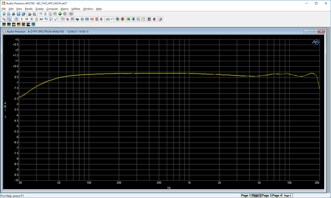
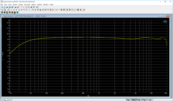
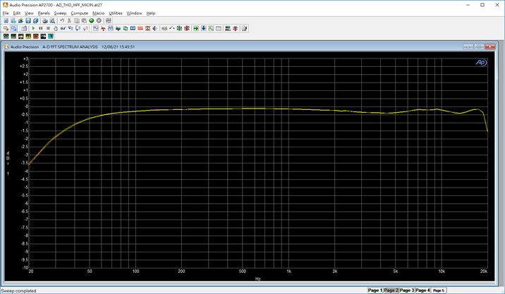
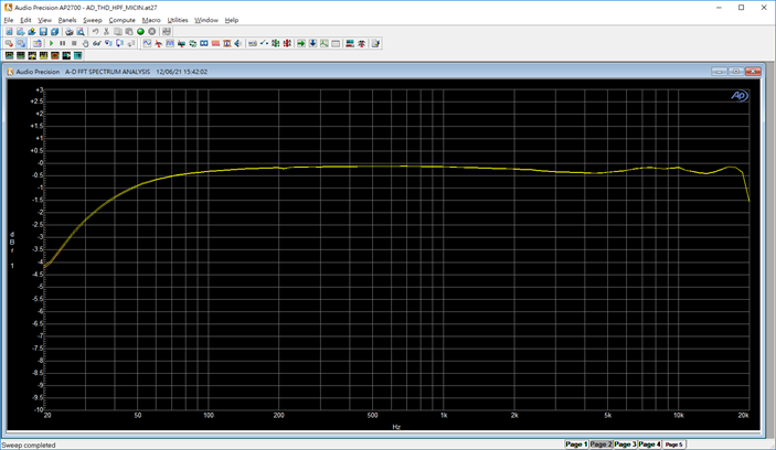
PS: The example waveform in the figure below is captured at a sampling rate of 48K
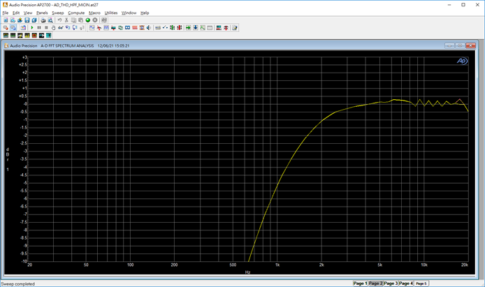
HPF off cut-off frequency 20Hz:
HPF 0x0 cut-off frequency 20Hz:
HPF 0x1 cutoff frequency 23Hz:
HPF 0x2 cutoff frequency 26Hz:
HPF 0x3 cutoff frequency 32Hz:
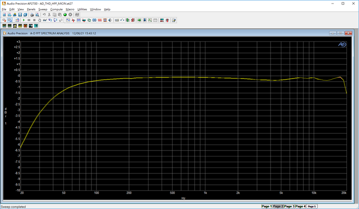
HPF 0x4 cutoff frequency 38Hz:
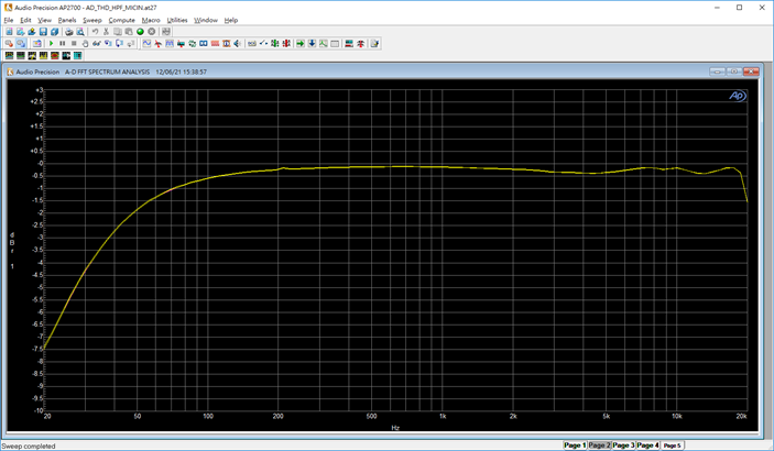
HPF 0x5 cutoff frequency 52Hz:
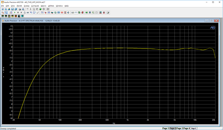
HPF 0x6 cutoff frequency 65Hz:
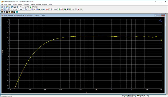
HPF 0x7 cutoff frequency 95Hz:
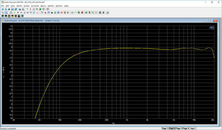
HPF 0x8 cutoff frequency 140Hz:
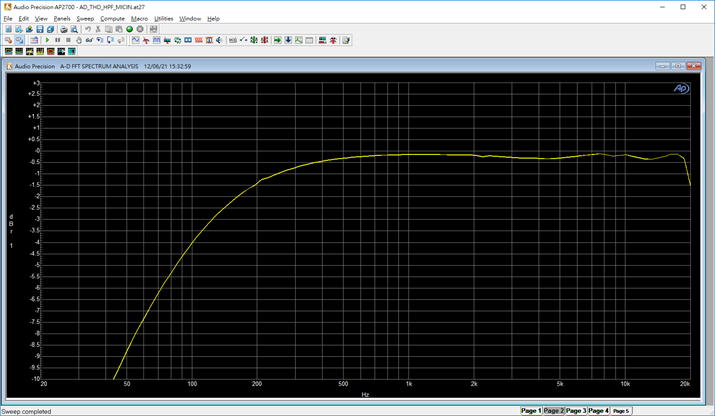
HPF 0x9 cutoff frequency 190Hz:
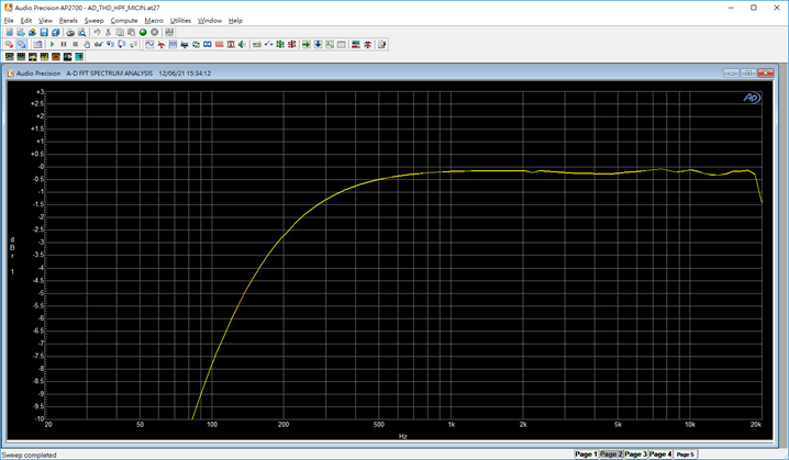
HPF 0xA cut-off frequency 250Hz:
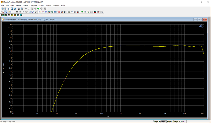
HPF 0xB cut-off frequency 370Hz:
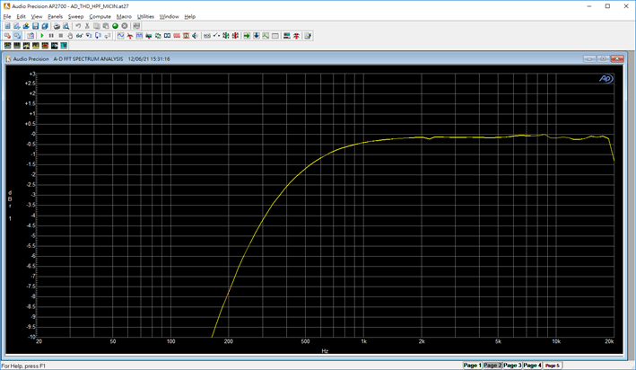
HPF 0xC cut-off frequency 480Hz:
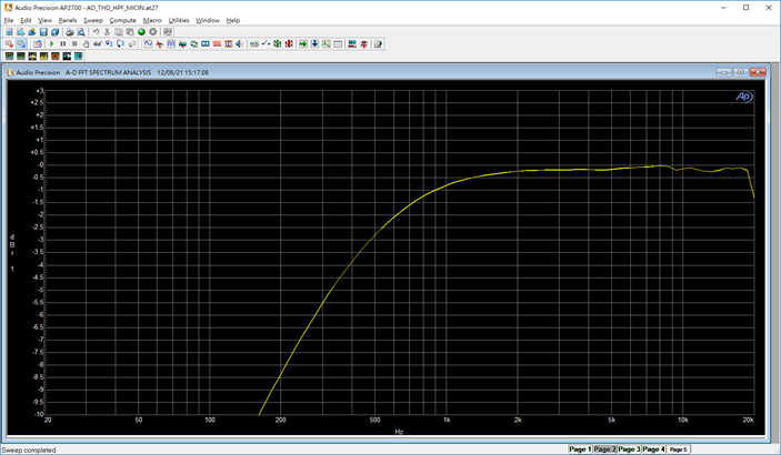
HPF 0xD cut-off frequency 700Hz:
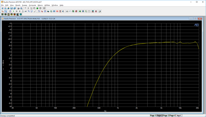
HPF 0xE cut-off frequency 950Hz:
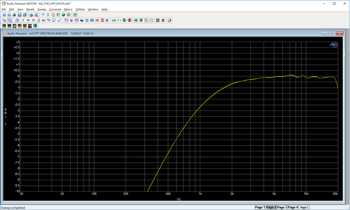
HPF 0xF cut-off frequency 1500Hz:
Relationship between sampling rate and cutoff frequency:
-
dmic bck mode
Property name Description Value range dmic-bck-mode Configure BCK mode 0~11 Gear Sampling rate BCK maximum value 0 NA no select 1 8k 600kHz 2 8k 1200kHz 3 8k 2400kHz 4 16k 800kHz 5 16k 1200kHz 6 16k 2400kHz 7 16k 4800kHz 8 32k 2400kHz 9 32k 4800kHz 10 48k 2400kHz 11 48k 4800kHz Example:
dmic-bck-mode = <3 6 9 11>; //2.4M, 2.4M, 4.8M, 4.8M The four parameters represent the BCK clock selected for 8K 16K 32K 48K sampling rate. The current example shows that: when the sampling rate is 8K, bck is gear 3, and the table shows 2.4Mhz When the sampling rate is 16K, bck is in gear 6, and the table shows that it is 2.4Mhz When the sampling rate is 32K, bck is gear 9, and the table shows that it is 4.8Mhz When the sampling rate is 48K, bck is in gear 11, and the table shows that it is 4.8Mhz Note: The sampling rate in the second column of the table indicates that only the corresponding sampling rate can take effect. For example, the 8K sampling rate only supports the selection of gears 1, 2, and 3; the corresponding BCK is 600khz 1.2mhz and 2.4mhz -
dmic-bck-ext-mode
Property name Description Value range dmic-bck-ext-mode dmic clock selection 0: Use dmic internal clock1: Use I2S RX BCK as DMIC clock for synchronization with I2S -
short-ff-mode
Property name Description Value range i2s-rx-short-ff-mode Configure how many BCKs I2S should delay before sending the MSB 0~3 i2s-tx-short-ff-mode Configure I2S to delay how many BCKs before sending the MSB 0~3 -
adc-out-sel
Property name Description Value range adc-out-sel Select the hardware entity of amic 0: adc0 (SDM_L) 1: adc1 (SDM_R) 2: adc2 (SDM_M) 3: adc3 Example:
adc-out-sel = <0 1 2 2>; //ADC_A ch0 corresponds to amic0, ADC_A ch1 corresponds to amic1, ADC_B ch0/1 corresponds to amic2 Note: iFackel only supports ADC_A and ADC_B, and does not support switching -
keep_anolog_power_on
Property name Description Value range keep_adc_power_on/keep_dac_power_on Whether to keep adc/dac power on. Turning on this configuration can save the delay time of adc/dac startup, but it will increase certain additional power consumption. 0: Disable; 1: Keep adc/dac power on -
amp pin configuration
Property name Description Value range amp-pad Select the pad pins of the left and right amplifiers and the high/low level configuration gpiopad 0,1 Example:
amp-pad = <PAD_PWM_OUT0 1 PAD_PWM_OUT 1>;
Note: For unified management, the pad parameter selection is placed in padmux.dtsi, so the parameters 1 and 3 PAD_PWM_OUT0 are actually ineffective. The PAD that is actually effective is placed in the MDRV_PUSE_AIO_AMP_PWR field of padmux.dtsi; the parameters 2 and 4 are effective on the dts side; a value of 1 indicates a high level to enable the amp, and a value of 0 indicates a low level to enable the amp