FLASH LIST ADDED FLASH SOP
REVISION HISTORY
| Revision No. | Description |
Date |
|---|---|---|
| 1.0 | 04/18/2023 | |
| 1.1 | 04/11/2025 | |
| 1.2 | 04/28/2026 |
1. OVERALL IDEA
Find a similar model that has been added, first configure the newly added flash according to the parameters of the similar model, and then make corresponding modifications according to the datasheet of the new flash. The meaning of each parameter is detailed below.
Use the NandInfoEditor software provided in the SDK package to open the flash_list configuration file.
Path:
nor flash:project/board/mehra/boot/nor/partition/flash_list.nri
spinand flash:project/board/mehra/boot/spinand/partition/flash_list.sni
After modification and saving, recompile and package the image, and then use the burning tool to burn the blank chip.
Note: The models in the nor flash list are all supported. The spinand flash needs to determine whether its flags and maxWaitTime parameters have values. Only when there is a value (non-0) does it mean that it is a supported spinand flash model.
2. sni / nri yaml text-based format
2.1. Purpose of text-based format
To make it more convenient and intuitive to modify the flash sni file, yaml files are introduced. You can directly modify the flash information through text editing, which also facilitates the modification of rom sni information for 4k page and 2 plane flash.
The flash driver ultimately still uses the flash_list.sni / flash_list.nri packaged in the cis.bin. The method of editing flash information has changed from flash editor to text yaml editing.
When adding a new flash, you can find a flash yaml of a similar model, copy it, and then modify the parameters that differ.
Currently, this process supports the following chips: pcupid, ifackel, ifliegen, ihalo, mhera.
2.2. Structure description
2.2.1 Path:
spinand flash:
    `project/board/mehra/boot/spinand/partition/sni_yaml/common/*`    (Collection of individual flash information for non-fast boot)
    `project/board/mehra/boot/spinand/partition/flash_list.txt`         (Generate flash_list.sni, used in conjunction with the common directory to determine which flash to use)

    `project/board/mehra/boot/spinand/partition/sni_yaml/fb/*`          (Collection of individual flash information for fast boot)
    `project/board/mehra/boot/spinand/partition/flash_list-fb.txt`    (Generate flash_list-fb.sni, used in conjunction with the fb directory to determine which flash to use)
nor flash:
    `project/board/mehra/boot/nor/partition/nri_yaml/common/*`          (Collection of individual flash information for non-fast boot)
    `project/board/mehra/boot/nor/partition/flash_list.txt`               (Generate flash_list.nri, used in conjunction with the common directory to determine which flash to use)

    `project/board/mehra/boot/nor/partition/nri_yaml/fb/*`                (Collection of individual flash information for fast boot)
    `project/board/mehra/boot/nor/partition/flash_list-fb.txt`          (Generate flash_list-fb.nri, used in conjunction with the fb directory to determine which flash to use)
2.2.2 yaml content description:
rom sni:
Specifically the spinor_basic_info and spinand_basic_info at the beginning of the yaml file, which were transparent in the previous editor.
Mainly for some flash with special requirements, such as parameter configuration for 4k page, 2 plane flash, for use by rom. Generally, no adaptation or modification is required.
sni / nri:
The specific data structure is spinor_info and spinand_sni. The meaning of each field is consistent with the previous editor description and has not changed.
2.2.3 Generation principle:
When make image is executed in the project directory, the corresponding tool is called to parse the content in flash_list.txt,
The corresponding yaml file content is taken out in order and the corresponding flash information is generated, and finally spliced into a complete flash_list.sni.
The same applies to spinor flash.
3. NOR FLASH
3.1. Add Flash
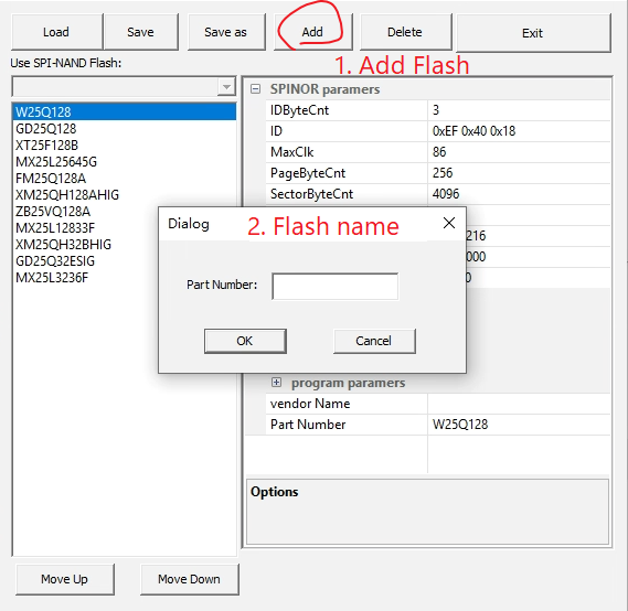
3.2. Basic Parameters (Flags)
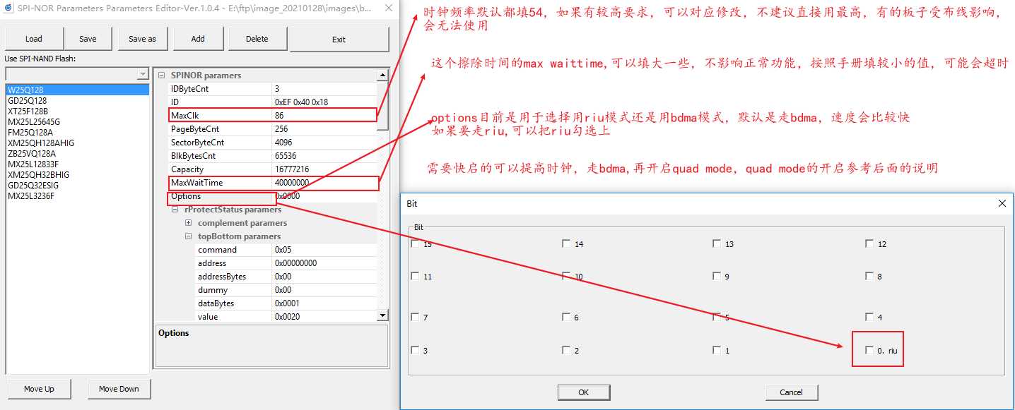
Figure 3-2: Flash_2
Parameter meaning:
-
PageByteCnt: the size of a flash page
-
SectorByteCnt: the size of a flash sector
-
BlkByteCnt: the size of a flash block
-
Capacity: the capacity of the flash = BlkByteCnt * (the number of blocks)
3.3. Protection Status Parameters
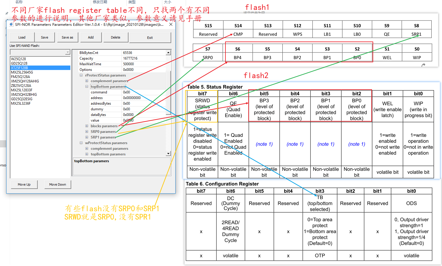
Figure 3-3: Flash_3
3.4. Read/Write Status Register
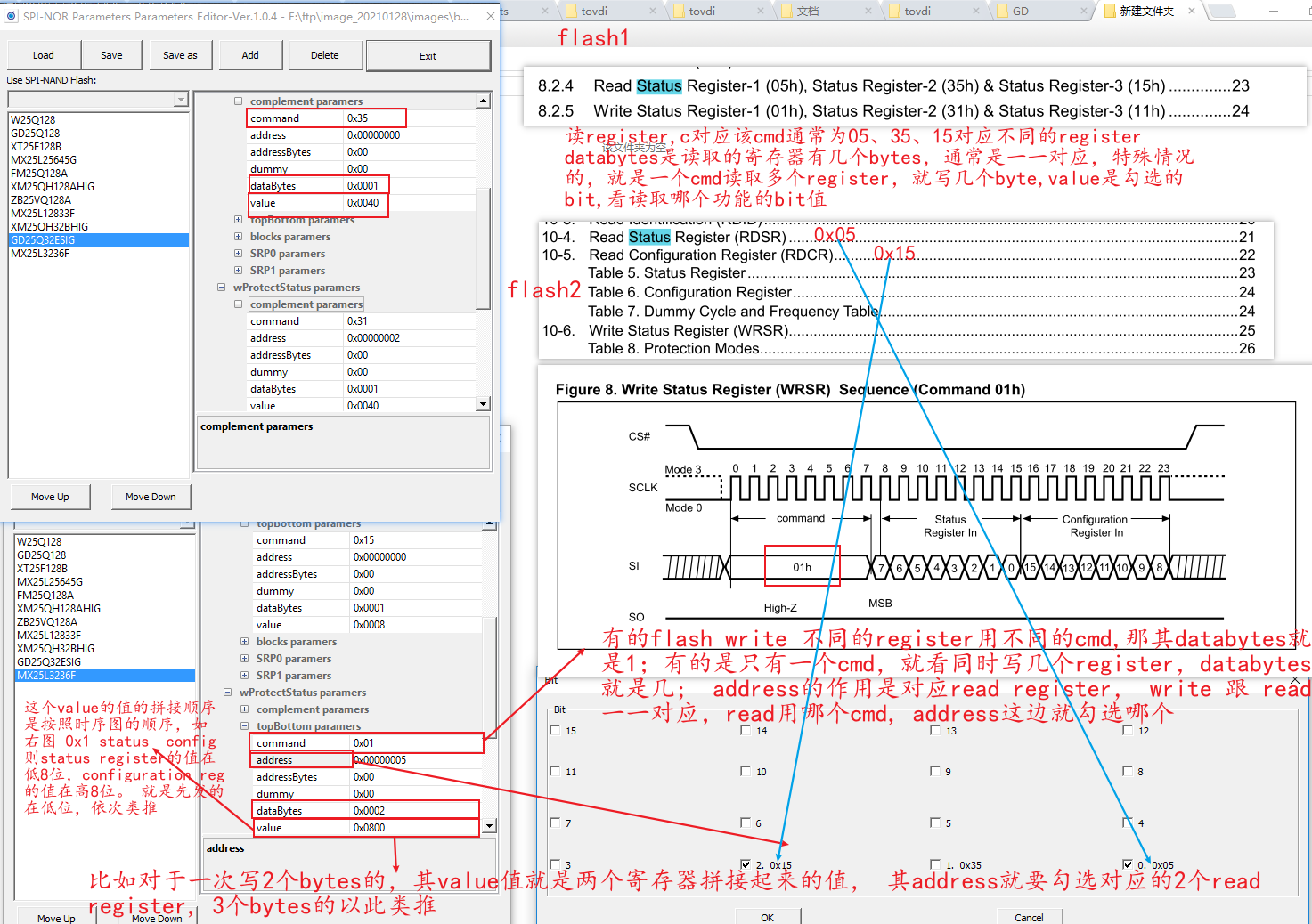
Figure 3-4: Flash_4
3.5. Quad Mode Register
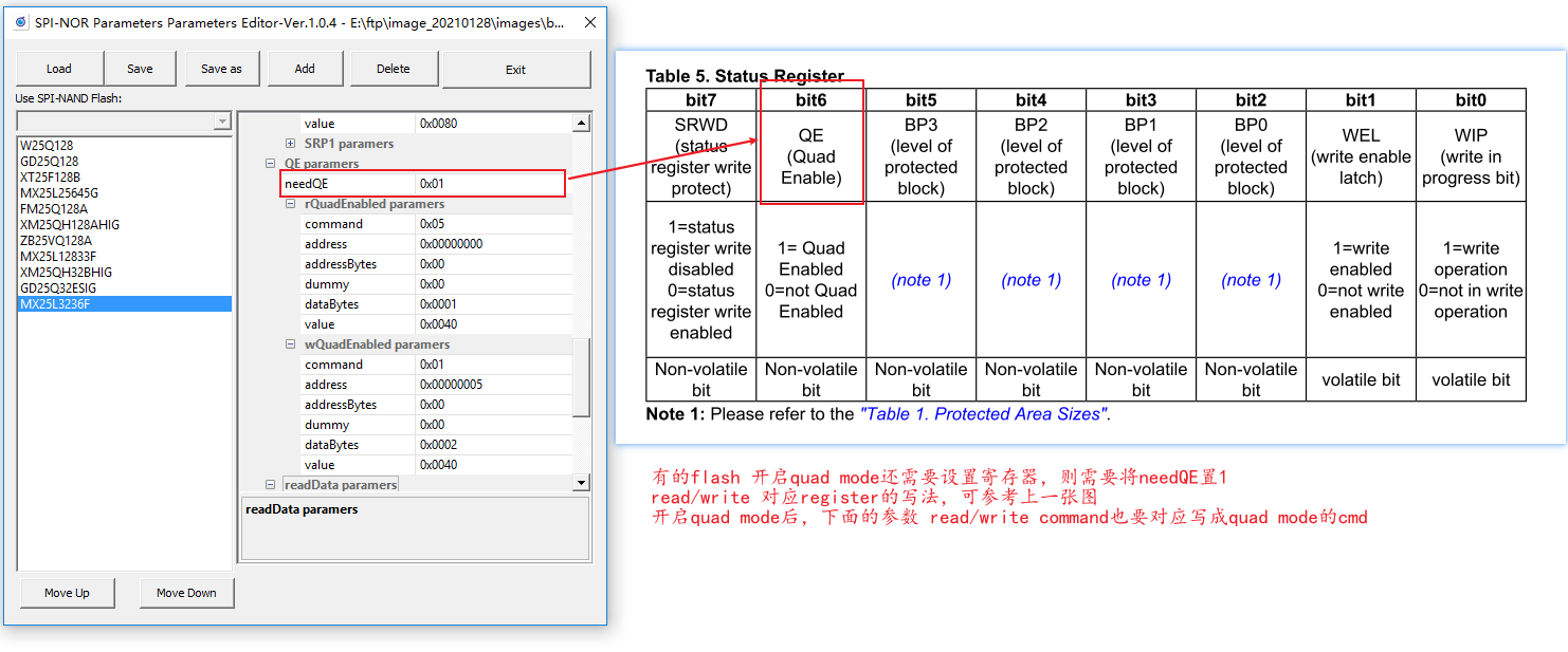
Figure 3-5: Flash_5
3.6. Read/Write Command
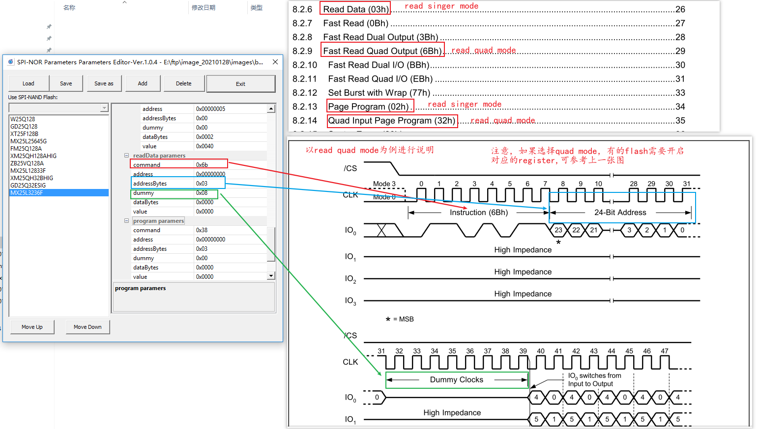
Figure 3-6: Flash_6
4. nand flash
4.1. Add Flash
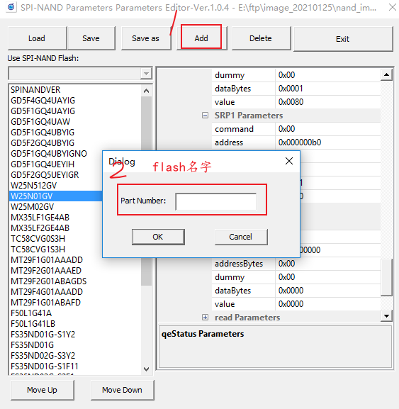
Figure 4-1: Flash_7
4.2. Basic Parameters
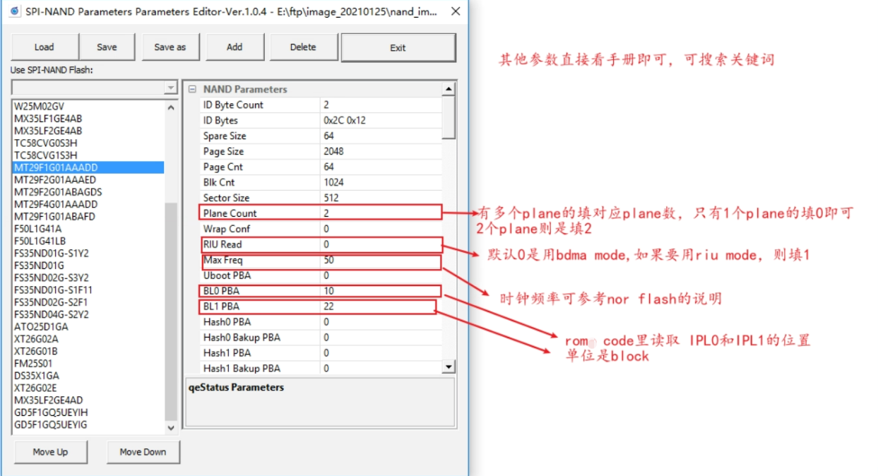
Figure 4-2: Flash_8
Parameter meaning:
-
Spare Size
- Size of flash oob area
-
Page Size
- Size of a flash page
-
Page Cnt
- How many pages are there in a flash block
-
Blk Cnt
- How many blocks are there in flash, total size of flash = page size * page cnt * blk cnt
-
Sector Size
- Size of a flash sector
4.3. flags
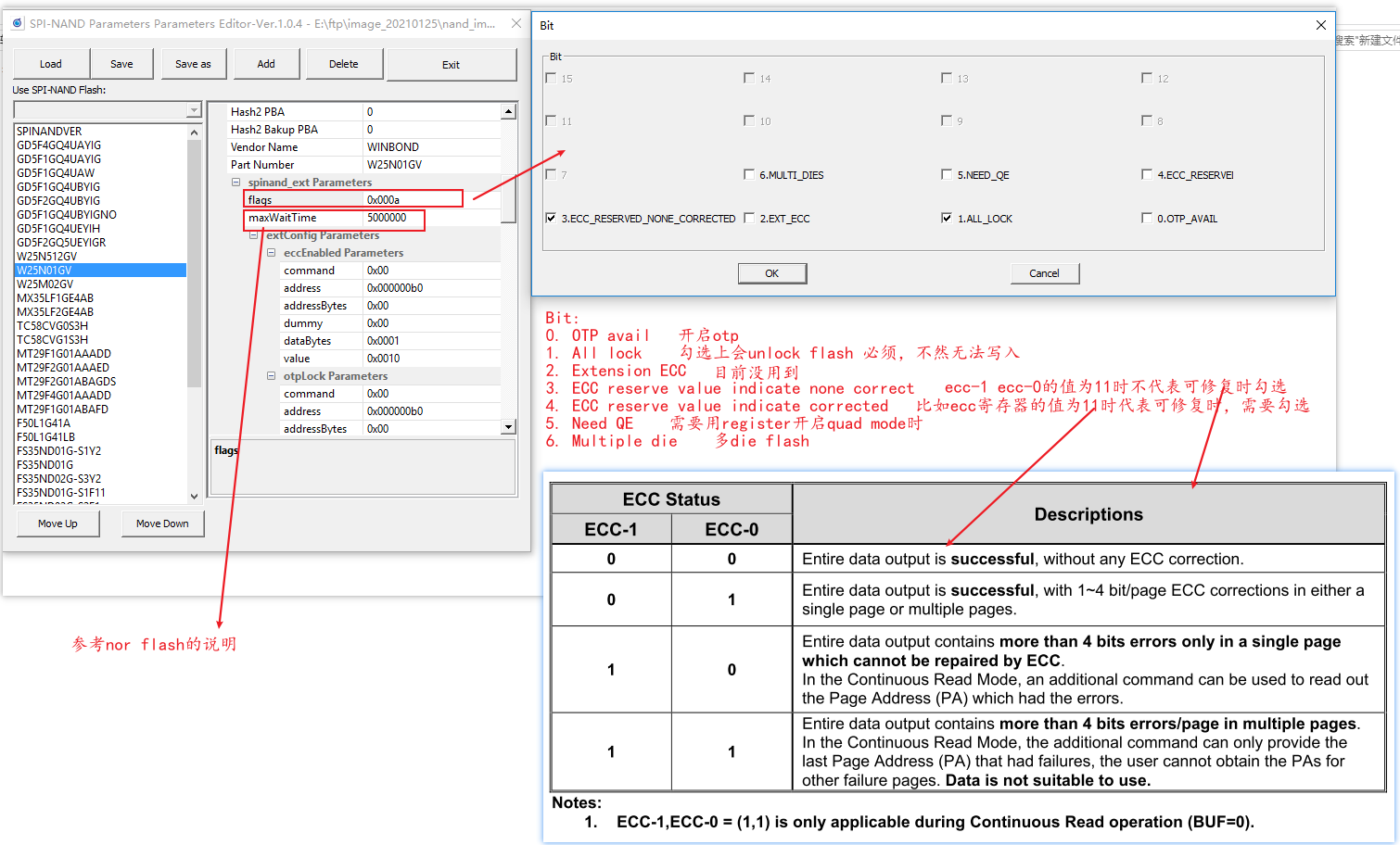
Figure 4-3: Flash_9
4.4. Status Register
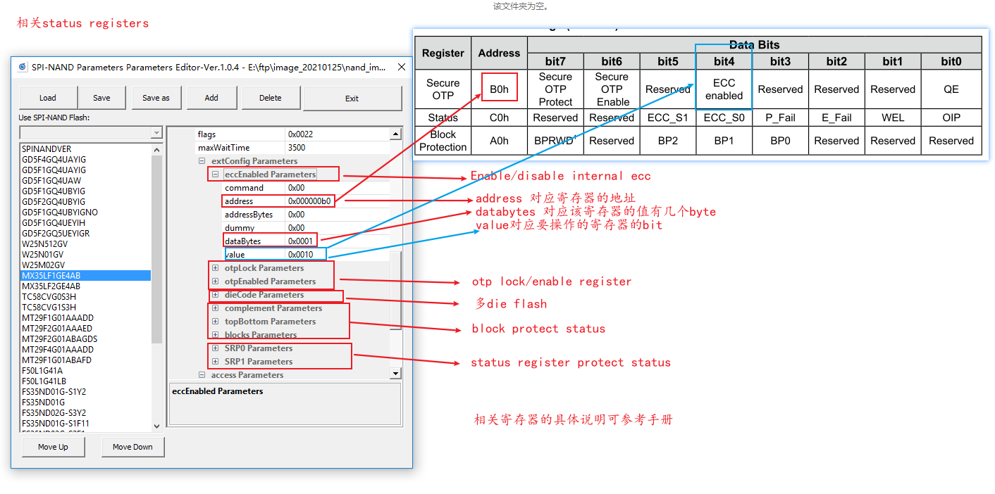
Figure 4-4: Flash_10
4.5. Read/Write Parameters
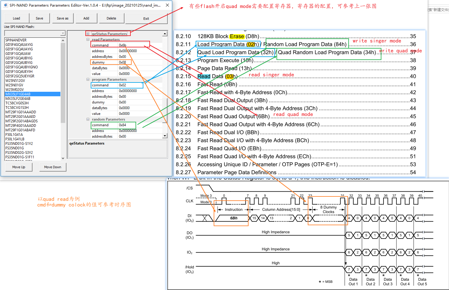
Figure 4-5: Flash_11
4.6. CR MODE (continue read)-None Buffer Mode
Except for special requirements, there is generally no need to click cr mode, which is more complicated and only used for IPL.
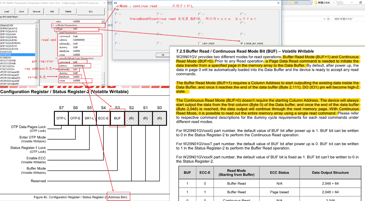
Figure 4-6: Flash_12
4.7. CR MODE (continue read)-Buffer Mode
Except for special requirements, there is generally no need to click cr mode, which is more complicated and only used for IPL.
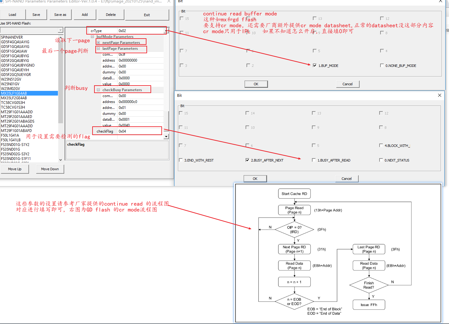
Figure 4-7: Flash_13