SDK Quick Start Guide
This document is based on the COMAKE PI D3 development board. It mainly introduces the D3 development board interfaces and describes the basic usage of the SDK, aiming to help you quickly get started with the D3 development board and become familiar with the SGS SDK package.
1. System Introduction
- The main chip SCM8003G adopts six-core ARM Cortex-A55, The maximum clock speed is 1.8GHz;
- VDD_CPU voltage: default 1.0V, software can adjust voltage with frequency;
- VDD_IPU voltage: default 1.0V, software can adjust voltage with frequency;
- VDD_Core voltage: default 1.0V, software can adjust voltage with frequency;
- DVDD_DDR voltage: default 1.0V, not adjustable;
- DRAM voltage: LPDDR4X-1.8V, 1.1V, 0.6V;
- IO voltage: 1.8V/3.3V;
- The core board carries an onboard 32bit 32Gbit LPDDR4X-3200Mbps;
- The core board carries an onboard 1.8V_EMMC with a capacity of 64GB;
- Supports 5-inch MIPI Panel (interface maximum Max 2560*1600@60fps);
- Has 3 USB2.0 ports and 1 USB3.0 port (USB2.0_P0 and P1 only support Host mode);
- Has 2 RGMII interfaces, the core board and base board each carry 1 GPHY, supporting 1000M/100M/10M auto-adaptation;
- Has 2 SATA interfaces, supporting 1.5/3/6Gbps, 1 SATA connector and 1 mSATA connector;
- Has 2 PCIe gen2*2 interfaces, 1 PCIe-64p connector and 1 M.2 B-key connector;
- Has an HDMI-TX interface, supporting v1.4b, maximum 3840*2160@30fps;
- Supports 2-channel AMIC differential input;
- Supports 4x2 DMIC input;
- Supports Lineout single-ended dual-channel output;
- Power input: 12V 3A;
- Core board normal operating temperature range: -20°C ~ +70°C;
1.1 Development Board Information
Base board front and back:

Main board front and back:

| No. | Component | Description |
|---|---|---|
| J1 | RTC PWR | RTC battery header |
| J2 | SODIMM CON | SODIMM connector |
| J4 | mSTATA | mSATA interface, supports mSATA hard disk |
| J7 | SATA PWR | SATA hard disk power interface |
| J13 | FAN CON | Fan interface, can control fan with PWM, default 5V, optional 12V |
| JP1 | 40P Expansion Header | 40pin header |
| JP2 | 30P Expansion Header | 30pin header |
| JPF6 | USB BOOT | Header for entering USB boot mode. After inserting the jumper cap, it switches to USB boot |
| JPF8 | USB3.0 PWR | USB3.0 VBUS power supply header for CONU8. When configured as HOST to power the Device, the jumper cap must be inserted |
| JPF9 | USB2.0 PWR | USB2.0 VBUS power supply header for CONU8. When configured as HOST to power the Device, the jumper cap must be inserted |
| JPO1 | DBG | Debug serial port, default baud rate 1500000. After flashing UBoot, the baud rate is 115200. It can also be switched to I2C mode to upgrade uboot with Sgs ISP Tool and read register information |
| JZ2 | DMIC | 4ch DMIC interface, supports up to 8 DMICs |
| JW1 | IPEX | IPEX socket for WiFi antenna |
| SDC2 | TF Socket | TF card socket |
| CN1 | M.2 B-KEY 2230 | M.2 B-Key socket, includes PCIe2.0*2 supporting Nvme SSD 2230 hard disk and a pair of USB2.0 supporting 4G module EM05-CN |
| CN4 | NANO-SIM CON | SIM card socket, used with the M.2 4G module |
| UW2 | USB-Wifi | Reserved USB WiFi module, connected to SSW105AT, USB P0 defaults to Type-A |
| CON4 | SPK_L | Left channel speaker interface, reserved AEC circuit routed back to MIC0 for hardware AEC |
| CON8 | MIPI Panel | MIPI-TX interface for connecting MIPI panel. The MIPI panel is connected via FPC, note not to connect it reversed |
| CON9 | TP CON | Touch interface, default left-side line sequence, default with opposite-side FPC ribbon cable. Near the screen side is FPC bottom-connection, near the main board side is FPC top-connection, note not to connect it reversed |
| CON10 | SPK_R | Right channel speaker interface, reserved AEC circuit routed back to MIC1 for hardware AEC |
| CON11 | USB2.0*2 | Double-layer USB2.0 interface, namely USB P0/P1, can only act as Host, upper layer is P0, lower layer is P1 |
| CON23 | MIC0 | Default connected to microphone, connecting Line In requires modifying the divider resistor on the board |
| CON24 | MIC1 | Default connected to microphone, connecting Line In requires modifying the divider resistor on the board |
| CONP2 | PCIE CON | PCIe connector, specification gen2*2 |
| CONS4 | SATA | SATA interface, supports SATA gen3 |
| CONG1 | RJ45 GE0 | Gigabit network port socket, built-in network transformer |
| CONG2 | RJ45 GE1 | Gigabit network port socket, built-in network transformer |
| CONH1 | HDMI | HDMI-TX interface |
| CONU8 | USB2.0+USB3.0 | Double-layer USB3.0+USB2.0 interface, upper layer is USB2.0, lower layer is USB3.0 |
| CONV1 | DC 12V | DC 12V power input interface |
1.2 Serial Port
Power: DC 12V; Debug serial port: TTL level, baud rate 115200
Connection method:
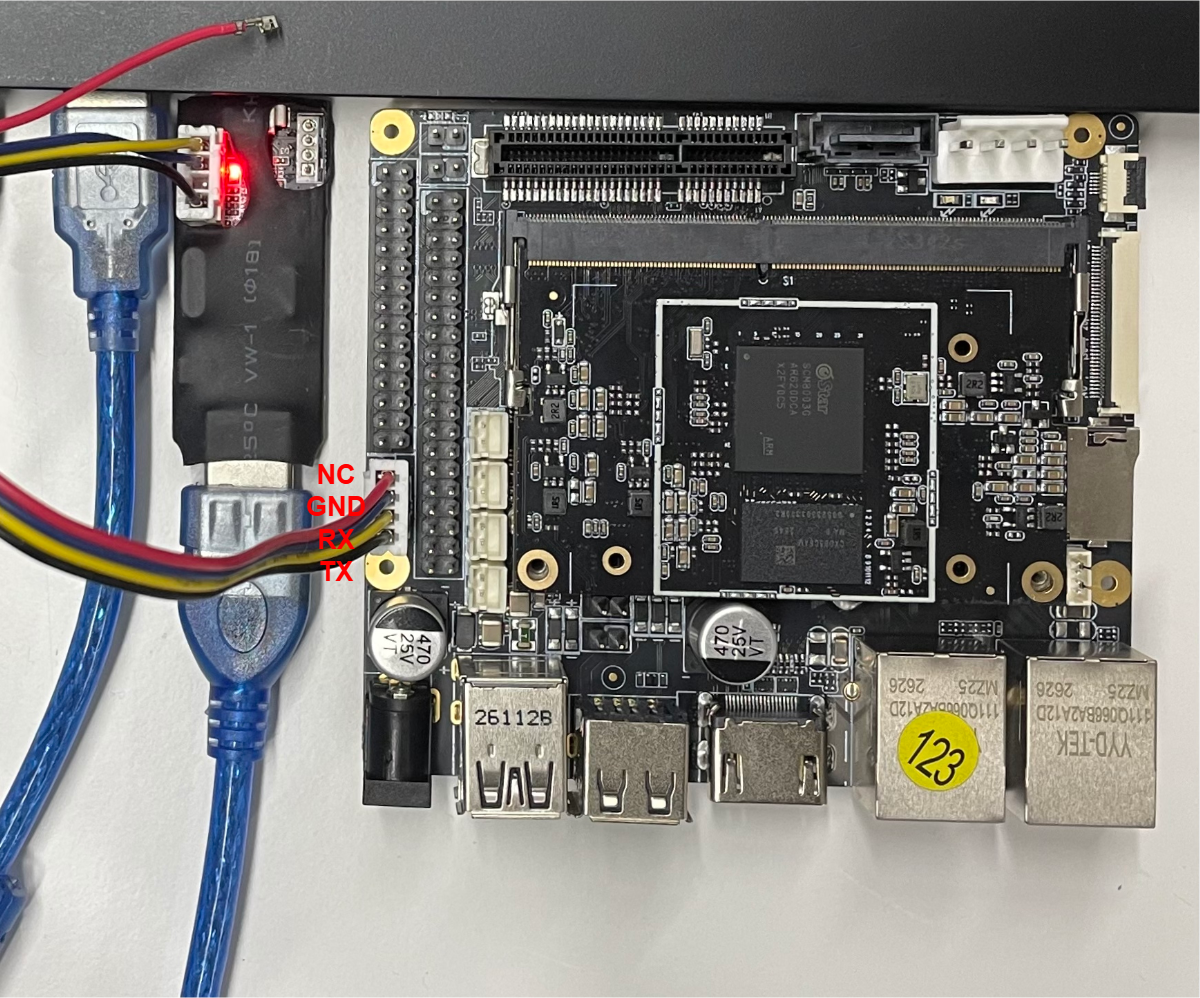
Connect the Type-A USB port of the Sgs Debug Tool sub-board to Windows, and connect the other end to the D3 Debug UART port. The connection method is shown in Figure 1-1.
Figure 1-1 D3 Board Uart Debug Connection Diagram
2. Environment Setup
2.1. Development Environment Overview
The mHera development environment typically consists of a Linux server, a Windows workstation and an EVB development board, all connected within the same network, as shown in Figure 2-1.
Development environment description:
- After the Bootloader (IPL+U-Boot) on the target board boots, the operation information of the target board is output to the host machine through the serial port for display.
- Enter commands in the console on the host machine to control the target machine.
- Set up a cross-compilation environment on the Linux server for program development.
- The Windows workstation is connected to the EVB board via a serial port for program development and debugging.
Figure 2-1 Embedded Development Environment Diagram
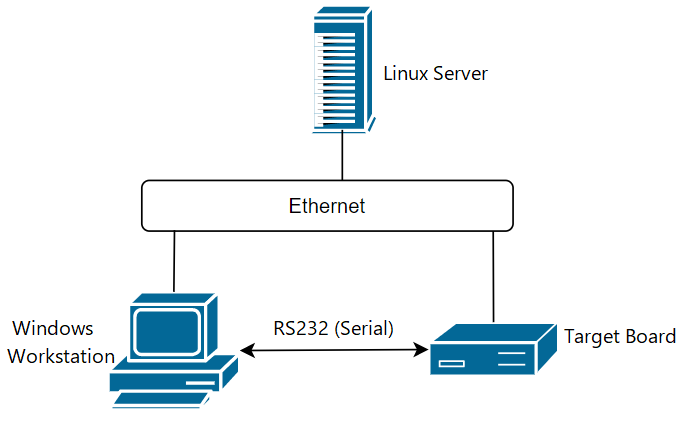
Table 2-1 Development Environment Software Description
| Platform | Operating System | Software Description |
|---|---|---|
| Windows workstation | Windows XP/7/10 | putty (or Xshell/SecureCRT, etc.), tftp server (tftpd32), SGS ISP tool (Flash_Tool_xxx.exe) |
| Linux server | Ubuntu or CentOS (Ubuntu 24.04 recommended) | NFS, telnetd, samba, vim, ARM cross-compilation environment, etc. |
| EVB development board | SGS Linux | The Linux kernel is ported from version 6.1.111, and the root file system is built based on busybox 1.33.0 |
2.2. Server Environment Setup
2.2.1. Server Hardware Requirements
A 64-bit Linux server is recommended, with the following specifications:
- CPU: Intel(R) Xeon(R) CPU E5-2450 0 @ 2.10GHz or better
- Memory: >= 16GB
- Hard disk: >= 600GB
- Network: Gigabit Ethernet
- Operating system: Ubuntu 22.04 64bit
Or a virtual machine with the equivalent configuration.
Verified systems:
| Server Distribution | Docker Version | Image Loading | Compilation |
|---|---|---|---|
| Ubuntu 24.04 | 20.10.21 | pass | pass |
2.2.2. Software Package Installation
Docker Environment Preparation
Step 1: Install dependency packages
Run the following command to install qemu-user-static, binfmt-support, and docker.io to provide cross-architecture execution capability and a container runtime environment:
sudo apt-get update && sudo apt-get install -y qemu-user-static binfmt-support docker.io
Step 2: Verify aarch64 cross-architecture support
After installation, run the following command to verify whether aarch64 cross-architecture support is enabled:
update-binfmts --display | grep "aarch64"
Expected output:
qemu-aarch64 (enabled):
 interpreter = /usr/libexec/qemu-binfmt/aarch64-binfmt-P
If it is not enabled, run:
sudo update-binfmts --enable
Step 3: Configure Docker user permissions (root users can skip this step)
Add the current user to the docker group to avoid having to use sudo every time you run a docker command:
sudo usermod -aG docker $USER
Note: After running the command above, you need to log in again or run
newgrp dockerfor the change to take effect.
Software Package Download
Step 1: Obtain Git download credentials
After registering an account on the Comake community, visit the Comake user center and note the following information for Git authentication:
-
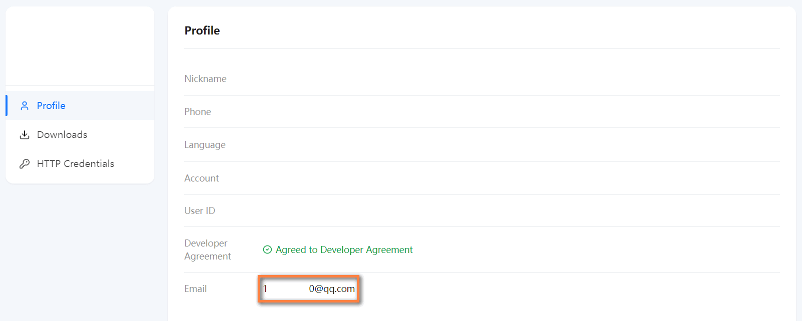
Email: The email used to register your Comake account.
-
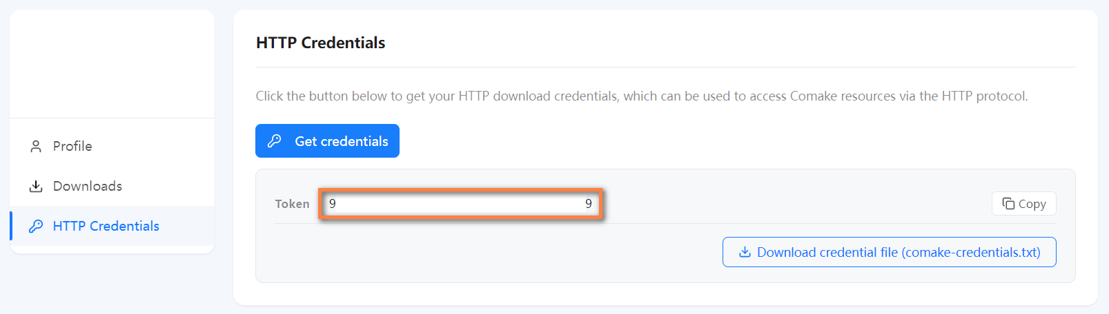
Token: On the “HTTP Credentials” page, click the “Get credentials” button to generate it.
Step 2: Configure the Git environment
-
Write the Git download credentials into the local
.netrcfile (so Git authenticates automatically without prompting for a username and password each time):echo "machine git.sigmastar.com.cn login <Email> password <Token>" >> ~/.netrc chmod 600 ~/.netrc -
Install the
repomulti-repository management tool (the download script uses it to fetch the SDK source code):sudo wget https://mirrors.tuna.tsinghua.edu.cn/git/git-repo -O /usr/bin/repo sudo chmod a+x /usr/bin/repo
Step 3: Download the scripts and packages
-
Download the scripts:
git clone https://git.sigmastar.com.cn:9090/sigmastar/download_scripts.gitAmong them,
D3_linux_setup.shis the one-click download script for the Linux packages, anddocker_versions.yamlcontains the relevant version information. -
Enter the download_scripts directory and run the script to download all resources in one click (including the Docker image, SDK source code, SDK toolset, algorithm models, etc.):
bash D3_linux_setup.sh allUsage of
D3_linux_setup.sh:Command Description bash D3_linux_setup.sh allOne-click download of all resources of the latest version bash D3_linux_setup.sh all <version>One-click download of all resources of a specified version bash D3_linux_setup.sh dockerDownload the latest version of the Docker image bash D3_linux_setup.sh docker <version>Download a specified version of the Docker image bash D3_linux_setup.sh sdk_toolchainsDownload the cross-compilation toolchain bash D3_linux_setup.sh sdkDownload the latest version of the SDK source code bash D3_linux_setup.sh sdk <version>Download a specified version of the SDK source code bash D3_linux_setup.sh imageDownload the latest version of the flashing firmware bash D3_linux_setup.sh image <version>Download a specified version of the flashing firmware bash D3_linux_setup.sh toolsDownload all tools bash D3_linux_setup.sh tools <tool_name>Download a single tool bash D3_linux_setup.sh model_zooDownload the latest version of the algorithm model library bash D3_linux_setup.sh model_zoo <version>Download a specified version of the algorithm model library bash D3_linux_setup.sh docsDownload the latest version of the documentation bash D3_linux_setup.sh docs <version>Download a specified version of the documentation bash D3_linux_setup.sh hw_ref_designDownload hardware reference design materials bash D3_linux_setup.sh list_versionView available version numbers bash D3_linux_setup.sh list_toolsView the list of available tools bash D3_linux_setup.sh build_imageBuild the latest version of the system image bash D3_linux_setup.sh build_image <version>Build a specified version of the system image
2.2.3. System Configuration
1. Set the default shell to bash
The build scripts use bash by default and require the system's default shell to be bash:
# Check the current shell
ls -la /bin/sh

# If it is not bash, change it
sudo dpkg-reconfigure dash
# Select <NO> in the pop-up interface
2. Set the default awk implementation
The build scripts use awk/gawk by default:
# Confirm the awk version
awk --version

# Install gawk (if needed)
sudo apt-get install gawk

# Configure the default awk to gawk
sudo update-alternatives --config awk
# Select gawk
3. Build Instructions / SDK Usage Guide
3.1. SDK Introduction
3.1.1. SDK Overall Architecture
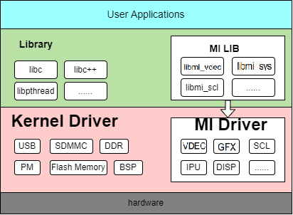
The SGS SDK architecture is divided, from top to bottom, into the application layer, software library layer, driver layer, and hardware layer.
- Application layer: the Linux applications developed by users, running in Linux user space.
- MI user interface layer: the MI SDK interfaces in user space. Applications access the MI Driver through this layer to operate the hardware.
- Driver layer: the concrete implementation of the MI driver.
- Hardware layer: the hardware of the SGS platform.
Design features:
- MI user interfaces are provided in the form of lib libraries.
- The SDK functional code is implemented in the driver layer to improve execution efficiency, and is provided in the form of ko (kernel module).
- User-space APPs can use the corresponding functionality by directly calling the MI interfaces.
Figure 3-1 SDK Software Architecture
3.1.2. SDK Directory Structure
SDK Directory Structure
| Directory | Description |
|---|---|
| boot | U-Boot bootloader. A secondary bootloader customized based on U-Boot, responsible for hardware initialization, kernel loading, and boot image signing/flashing. |
| kernel | Linux kernel. The Linux kernel source code adapted to the SGS SoC, including vendor-specific drivers. Customers can customize kernel configurations and device trees here. |
| sdk | Core media/platform SDK. Contains the kernel drivers, user-space libraries, HAL implementations, and sample/demo applications for all media processing modules (video codec, ISP, display, audio, etc.). This is the main working directory for customers to integrate applications and customize media pipelines. |
| project | Build environment and project entry point. The build environment directory of the entire SDK, containing the top-level Makefile, board-level configuration (board/), image packaging scripts (image/), kernel/SDK build integration (kbuild/), release output (release/), and various host-side tools (tools/). Customers configure and build the entire project through the Makefile and defconfig under this directory. |
| optee | OP-TEE secure execution environment. Contains the trusted OS (optee_os), client library (optee_client), example trusted applications (optee_examples), and test suite (optee_test), used for security scenarios such as DRM, secure storage, and cryptography. |
3.1.3. SDK Tools Toolset
The SDK provides a rich set of development tools, located under the SDK/Tools/ directory, which can help developers improve development efficiency.
| Tool | Brief Introduction |
|---|---|
| BWLATool | Bandwidth and latency analysis tool, monitors DDR bandwidth in real time and configures QoS parameters for each IP, supporting multi-IP data comparison |
| CalibrationTool | DDR memory calibration tool, used to calibrate DRAM timing parameters and generate optimized MIU initialization scripts |
| FlashTool | Serial flashing tool, writes firmware to the on-board Flash storage via UART |
| GenScalerTbl | SCL filter coefficient generation tool, used to generate custom image scaling interpolation coefficient tables to optimize scaling image quality |
| IQTool | Image quality debugging tool, used for tuning and verifying ISP image quality |
| MakeBin | Master image creation tool, supports master image creation for mass production on three storage media: SPINAND/SPINOR/eMMC |
| PQTool | Image quality debugging tool, adjusts display parameters such as Gamma, CSC, sharpness, and color online, with real-time preview of the image |
| sgs_comake_tools | Environment setup tool, used to build the root file system and images |
| SystemTool | System debugging tool, supports online register read/write, batch script read/write, register comparison, and OTP burning |
| Tftpd | TFTP server tool, used for network flashing |
| ToolChain | Cross-compilation toolchain, used to compile embedded programs for target architectures such as ARM on a PC |
| UartBurnTool | UART firmware upgrade tool, writes the upgrade image to the on-board Flash storage via the serial port when the chip is empty (no firmware) |
| USBFactoryTool | USB firmware upgrade tool, writes the packaged USB upgrade image to the on-board Flash storage via USB, supporting automated production-line upgrades |
| UsbDevelopTool | USB firmware upgrade tool, writes the USB upgrade firmware to the on-board Flash storage via USB, supporting both full-package upgrade and single-partition upgrade |
3.1.4. Main Functional Modules
| Module | Full Name | Functional Description |
|---|---|---|
| SYS | System | MI system initialization, memory management, data flow management |
| SCL | Scaler | Scaling/cropping/format conversion, etc. |
| VDISP | Virtual Display | Software picture composition |
| VENC | Video Encoder | H264/H265/MotionJpeg encoding |
| AI | Audio Input | Audio capture |
| AO | Audio Output | Audio output |
| DISP | Display | Video processing and display |
| FB | Frame Buffer | Graphic layer device driver implemented based on Linux Framebuffer |
| GFX | Graphic Engine | Provides fast graphics drawing functions on hardware |
| RGN | Region | Region management module |
| HDMI | High Definition Multimedia Interface | High-definition multimedia interface |
| IVE | Intelligent Video Engine | Basic operators for intelligent recognition algorithms |
| IPU | Intelligent Process Unit | AI model inference acceleration |
| IPU_CASCADE | IPU Cascade | Interface for multi-IPU parallel cascaded inference of large models, used to collaboratively accelerate offline cascaded model inference such as LLM on local/remote IPU boards |
| JPD | Jpeg Decoder | JPEG decoding module |
| VDF | Video Detect Function | Video detection |
| VDEC | Video Decoder | Video decoding |
| CIPHER | Cipher | Data encryption/decryption: AES/RSA/SHA algorithms |
3.2. Building the SDK
If you only need to build with the default parameters, you can directly build and generate the SDK image with the following command. (This command starts and enters a Docker container by default.)
bash D3_linux_setup.sh build_image
If you need to modify the build configuration before building, refer to the description in the following sections.
3.2.1. Enter the Docker Container
SDK building is performed inside a cross-compilation Docker container. Start and enter the container under the download_scripts directory:
docker run --privileged --rm -w /home/sgs -it -v $(pwd):/home/sgs docker.sigmastar.com.cn/sigmastar/sgs_debian_rootfs:<version> /bin/bash
<version>is the Docker image version number. Please refer todocker_versions.yaml, for example 2.0.0
After entering the container, you can configure the cross toolchain.
3.2.2. Cross-Compilation Toolchain Download and Installation
Determine the toolchain
Determine the cross toolchain to be configured according to the defconfig determined in Confirm and Configure defconfig:
Main toolchain
| defconfig Toolchain Version field | Toolchain | CROSS_COMPILE |
|---|---|---|
| glibc-12.4.0 |
Obtain the toolchain
The cross toolchain can be obtained from Tools/ToolChain/ in the root directory of the SDK release package.
Installation
Main toolchain:
64-bit toolchain: aarch64-unknown-linux-gcc-12.4.0-glibc-2.37-gnu.tar.xz
# Step 1: Create the tool directory
sudo mkdir -p /tools/toolchain

# Step 2: Extract and install
sudo tar -xJvf ./aarch64-unknown-linux-gcc-12.4.0-glibc-2.37-gnu.tar.xz -C /tools/toolchain

# Step 3: Configure environment variables
export PATH=${PATH}:/tools/toolchain/aarch64-unknown-linux-gcc-12.4.0-glibc-2.37-gnu/bin
export CROSS_COMPILE=aarch64-unknown-linux-gnu-12.4.0-
export ARCH=arm64
It is recommended to add the environment variables to
~/.bashrcor/etc/profileto make them permanent.
3.2.3. Confirm and Configure defconfig
Select different defconfigs according to different application scenarios.
The following are the defconfigs supported by the SDK by default
| No. | defconfig | Hardware Description |
|---|---|---|
| 1 | linux-comake_mhera.emmc.glibc-12.4.0-arm64-ext4.d3.4096.fccsp16_lpddr4x_defconfig | For Comake PI D3 EVB board, built-in 4096MB LPDDR4X chip silk-screen SCM8003G, storage is emmc |
| 2 | linux-comake_mhera.emmc.glibc-12.4.0-arm64-ext4.d3.2048.fccsp16_lpddr4x_defconfig | For Comake PI D3 EVB board, built-in 2048MB LPDDR4X chip silk-screen SCM8003G, storage is emmc |
defconfig description
The SDK image defconfig is located in the project/configs/verify/defconfigs/ directory. Take linux-comake_mhera.emmc.glibc-12.4.0-arm64-ext4.d3.4096.fccsp16_lpddr4x_defconfig as an example:

| defconfig field | Description |
|---|---|
| OS | Linux |
| community | comake |
| platform | mHera |
| boot medium | emmc |
| toolchain | glibc-12.4.0 |
| rootfs type | ext4fs |
| DDR size | |
| package | fccsp16 |
defconfig configuration item description
The SDK configuration is located in the project/configs/verify/defconfigs directory, and the defconfig file is an important file for SDK building.
project/configs/current.configs records the latest configuration item descriptions.
Refer to Alkaid defconfig Introduction
3.2.4. Full Build
cd project
# Select the corresponding defconfig according to the hardware configuration
make <defconfig name>  # Example: make linux-comake_mhera.emmc.glibc-12.4.0-arm64-ext4.d3.4096.fccsp16_lpddr4x_defconfig
make clean; make image -j16
After the build completes, you can obtain all the image files required for flashing from the project/image/output/images/ directory.
3.2.5. Building the Kernel
Enter the kernel directory to build it separately:
cd kernel
make <kerenl_config> # This step is not needed if you have already run make image under project. Example: make mhera_comake_d3_linux_emmc_defconfig
make -j16
Output directory of the generated files: kernel/arch/arm64/boot/uImage.xz
3.2.6. Building U‑Boot
cd boot
make <xxx_config>  # This step is not needed if you have already run make image under project. Example: make mhera_comake_d3_emmc_arm64_defconfig
make -j16
Output directory of the generated files: boot/u-boot.xz.img.bin (emmc; spinand: boot/u-boot_spinand.xz.img.bin)
3.2.7. Building ko Modules
There will inevitably be some coupling between the SDK and the Kernel, which means that when customers configure and trim the Kernel themselves, they need to rely on SGS to re-release the SDK ko.
To decouple the SDK from the Kernel, the SDK source code that needs to depend on the kernel source code is open-sourced into the sdk/linux directory. When customers configure and trim the Kernel themselves, they can recompile the SDK ko themselves.
How to recompile ko after modifying the kernel (note: configure the toolchain environment variables first):
Full build:
For toolchain configuration, refer to 2.2.2 Cross-Compilation Toolchain Download and Installation
Fast build:
# 1. Configure the necessary paths
export PROJ_DIR=/home/xxx/project
export KDIR=/home/xxx/kernel

# 2. Build & package
cd sdk/linux
make clean ; make all -j32
make install -j32
cd ../../project
make image-fast -j16
Build a single mi_xxx.ko (taking mi_ai.ko as an example):
Ignore certain modules:
export FILTER_OUT_MODULES=shadow
# Or ignore multiple modules
export FILTER_OUT_MODULES="shadow ipu"
3.2.8. Building Apps
# Building apps requires that the SDK has already been built
cd sdk/verify/sample_code
# Build all demos
make all
# Build a single demo
make demo/{demo_name}
Output directory of the generated files: sdk/verify/sample_code/out/
3.3. Flashing Images
3.3.1. USB Factory Tool Flashing
SGS provides USB_Factory_Tool to support USB image upgrade. For details, refer to USB Upgrade: USB Factory Tool Upgrade
3.3.2. Flashing via TFTP Network
PC-side setup:
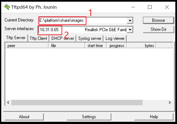
- Run the tftp tool, pointing to the
project/image/output/images/directory (or copy the files to another directory separately) -
Select the correct network adapter
-
Connect the board's network port to the PC (in the same network segment as the PC), connect the Debug serial port tool to the PC, and check the correctness of the connections
Board-side operations:
- Press and hold the Enter key on the computer keyboard, then power on the board. The board will enter the bootloader command line.
-
Set the network parameters (required for the first flashing or when the IP changes):
setenv ipaddr 10.31.0.10; // Set the board IP, must be able to ping the PC setenv serverip 10.31.0.29; // Set the PC IP setenv -f ethact sgs_gmac0; // Set to use gmac; this platform uses gmac setenv -f ethaddr 00:70:20:00:00:01; // Set the MAC address setenv -f netmask 255.255.252.0; // Set the netmask setenv -f gatewayip 10.34.19.254; // Set the gateway saveenv; -
Execute the automatic network flashing:
estar
Note
- To ensure a successful flashing, please use a static IP and make sure the PC and the development board are in the same network segment.
- You can use an independent network adapter to directly connect the PC to the development board, and fix the internal IP address of that network adapter.
3.3.3. Using ISP Tool to Upgrade an Empty Chip into U‑Boot
Please confirm the ISP Tool version. The ISP Tool is packaged in the tool directory at the time of the first version release.
Note: During project development or on different projects, the partition layout may be different. For the actual partition in use, please refer to
images/partition_layout.txtin the built images.
NAND Emmc flashing steps:
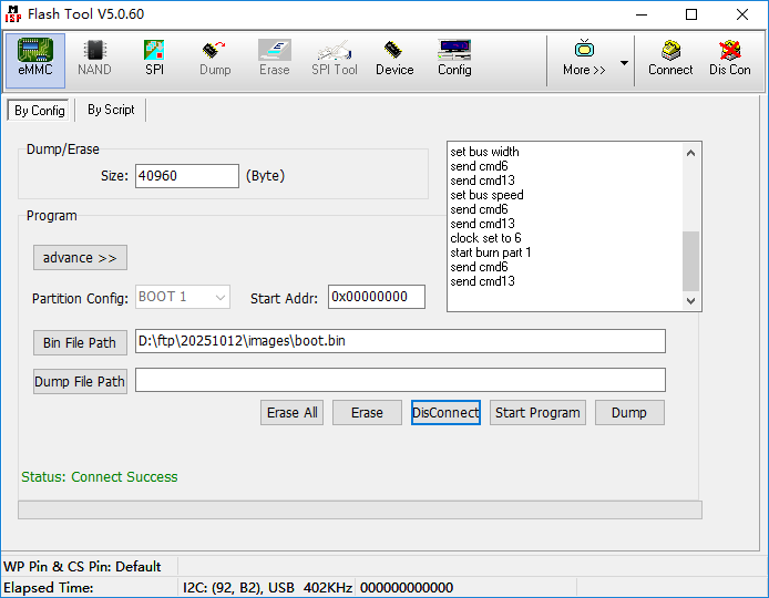
Click Connect to connect to the board. Retry the connection by power-cycling the board multiple times.
Warning
If nor/nand flashing works fine but emmc keeps reporting 'Connect Fail', try updating the Flash Tool to the latest version and try again! emmc enables AB partition by default. If it cannot successfully enter the kernel after 14 boots, it will halt directly in ipl, and re-flashing with isptool will still get stuck here:
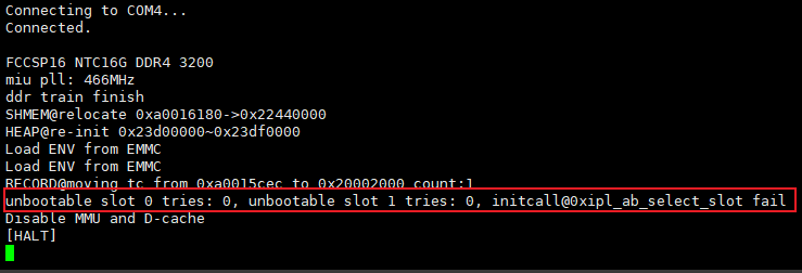
This is caused by the env not being erased cleanly. Generally, re-flashing the emmc boot.bin is required. Please strictly follow these steps:
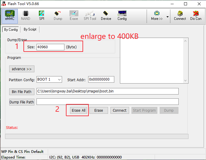
step1. Because emmc has three physical partitions that can be used as the boot partition, please click erase all before flashing, and adjust the size to 400KB:
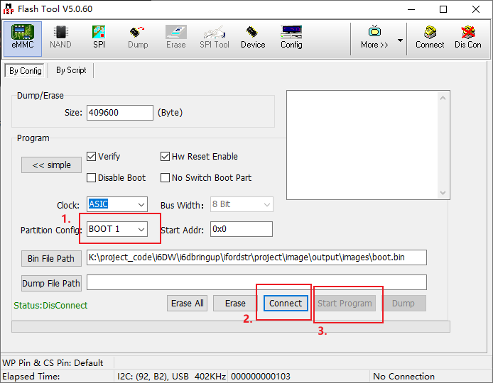
step2. Then select the partition to be flashed, and click connect -> start programe in sequence:
3.3.4. Other Upgrade Methods
SD card upgrade: USB Drive & SD Card Upgrade
UART upgrade: UART Upgrade
3.4. Master Image Tool Introduction
The master image tool is used to create master images for NAND/NOR/EMMC.
Usage reference: SDK Tools Toolset
4. Software Architecture Introduction
SGS releases a variety of sample code as references along with the SDK, located under sdk/verify/sample_code/demo. For detailed descriptions of the sample code, please refer to the readme_en.md under the corresponding demo.
The First Application
| Application | Usage Link |
|---|---|
| Deep Learning | DLA_demo |
| Graphics Processing | GFX_demo |
| Large Model | LLM_and_VLM_demo |
| NVR | NVR_demo |
5. Software Development Guide
5.1. Build-Related Issues
5.1.1. Compilation reports that the cross-compilation toolchain cannot be found?
# Solution: Confirm the toolchain path configuration
export PATH=${PATH}:/tools/toolchain/aarch64-unknown-linux-gcc-12.4.0-glibc-2.37-gnu/bin
export CROSS_COMPILE=aarch64-unknown-linux-gnu-12.4.0-
export ARCH=arm64

# Verify the toolchain
aarch64-unknown-linux-gnu-12.4.0-gcc --version
5.1.2. make image fails or the image is incomplete?
# Check disk space
df -h

# Clean and rebuild
make clean
make image -j32

# If it still fails, try a single-thread build to see the detailed error
make image -j1
5.2. Flashing-Related Issues
5.2.1. ISP Tool cannot connect to the development board?
- Check the serial connection: confirm that the USB-to-serial driver is installed
- Check the baud rate setting: 115200
5.2.2. TFTP flashing transfer fails?
# Check network connectivity
ping 10.31.0.29  # PC IP

# Ensure a static IP is used, in the same network segment
setenv -f ipaddr 10.31.0.10
setenv -f serverip 10.31.0.29
saveenv

# Re-execute flashing
estar
5.2.3. The system cannot boot after flashing?
- Check whether the Flash type is selected correctly
- Verify the partition table configuration:
cat images/partition_layout.txt - Check the serial boot log to confirm whether the bootloader is loaded normally
- Try re-flashing the complete firmware package
5.3. System-Related Issues
5.3.1. How to use coredump to debug application crashes?
-
gdb location
The SDK provides a pre-compiled gdb, located at
project/release/common_prebuilt/glibc/12.4.0/arm64/debug/gdb -
Set the coredump file size on the board
ulimit -c unlimited -
View the stack information in the coredump file
gdb ./your_app /path/to/core
5.3.2. How to trace MI module data flow?
-
Refer to the Sgs NVR Application Development Guide, run the demo on the platform and keep it running.
-
View the VDEC/DISP node information, which includes the binding relationship with the upstream module cat /proc/mi_modules/mi_vdec/mi_vdec0
cat /proc/mi_modules/mi_disp/mi_disp0
-
Exit the demo after viewing the node information.
5.3.3. How to enable kernel debug logs?
# Method 1: Modify in the U‑Boot environment bootargs variable:
loglevel=7

# Method 2: Modify at runtime
echo 7 > /proc/sys/kernel/printk
# View dmesg
dmesg | grep -i "your_keyword"
5.3.4. What to do if performance does not meet the target?
-
Insufficient frame rate
Check whether the module CLK configuration meets the frame rate requirements
-
Insufficient bandwidth
Check whether the binding method between stream pipe IPs meets expectations
-
CPU loading too high
Use perf to capture a flame graph and view the specific modules. If the APP usage is too high, check the corresponding implementation. If an SGS module is too high, please contact FAE
5.3.5. How to add a third-party library to the SDK build?
Refer to the following steps:
-
Check the configuration
Check the configuration in
{SourceCode}/project/configs/current.configs:CONFIG_MI_SDK_SUPPORT = y # Generally enabled by defaultIf it does not exist, the defconfig selection during the full build is incorrect.
-
Place the library source code in an appropriate directory
mkdir -p {SourceCode}/sdk/verify/sample_code/3rdparty/mylib # Create the directory cp -r your_lib {SourceCode}/sdk/verify/sample_code/3rdparty/mylib/ # Place the source code to be added (.c and .h files) -
Create Makefile build rules
touch {SourceCode}/sdk/verify/sample_code/3rdparty/mylib/lib.mk
# If the source code (.c and .h files) is placed directly in the mylib directory, as follows # mylib/ # | # |——xxx.c # |——xxx.h # |——xxx.c # |——xxx.h # |....... then the lib.mk file can be empty # If there are subdirectories and additional header files, as follows # mylib/ # ├── include/ ← header files placed in this subdirectory # │ └── xxx.h # ├── src/ ← source code placed in this subdirectory # │ └── xxx.c # |—— lib.mk # |—— xxx.c # |—— xxx.h # |...... then lib.mk needs to add search paths for the relevant .h and .c files INC += $(MODULE_PATH)/include SUBDIRS += $(MODULE_PATH)/src -
Declare dependencies in the APP's dep.mk
Find the APP directory that will use this library, e.g.
{SourceCode}/sdk/verify/sample_code/demo/my_demo/, and edit its dep.mk:DEP += 3rdparty/mylib # If dep.mk does not exist, you need to create oneNote: If this step is missing (when needed), no output will be generated after compilation.
-
Rebuild the entire SDK
# Switch to {SourceCode}/project
cd project
make image -j16  # Build
After compilation, the following results will be generated:
{SourceCode}/sdk/verify/sample_code/out/arm/libs/glibc/12.4.0/staticcontains libmylib.a{SourceCode}/sdk/verify/sample_code/out/arm/libs/glibc/12.4.0/dynamiccontains libmylib.so
5.3.6. How to add a new application to the SDK?
5.3.6.1. Step 1: Create the DEMO Directory
Create a new demo directory under the demo/ directory. It is recommended to use lowercase letters and underscores, for example my_demo.
5.3.6.2. Step 2: Create the Configuration Files
1. Create the my_demo.mk file
Each demo must have a .mk file with the same name as the directory. The file name must be consistent with the directory name.
Naming rule:
- File name:
[directory name].mk - For example:
my_demo.mk
Required variables:
# Enable clang-format code format checking
CLANG_FORMAT_ENABLE := yes

# Enable clang-tidy static analysis
CLANG_TIDY_ENABLE := yes

# Define the generated executable file name
# Naming format: sgs_demo_[underscore-separated path segments]
EXEFILE := sgs_demo_my_demo
Optional variables:
# External library link type (optional)
LINK_TYPE := static    # Static linking (default)
# or
LINK_TYPE := dynamic   # Dynamic linking

# Internal library link type (optional)
INTER_LINK_TYPE := static    # Static linking (default)
# or
INTER_LINK_TYPE := dynamic   # Dynamic linking

# Add external library dependencies (optional)
LIBS += -lmi_sys
LIBS += -lmi_common
2. Create the dep.mk file
This file is used to declare internal library dependencies.
Without dependencies:
With dependencies:
# Add internal library dependencies
DEP += 3rdparty/sgs_rtsp
DEP += libraries/some_lib

# Add header file search paths
INC += $(BUILD_TOP)/../../../kernel/drivers/sgs_common/include/
5.3.6.3. Step 3: Create the Source Code File
The source file must be named sgs_demo.c
Basic program structure:
#include <stdio.h>
#include <stdlib.h>
#include <string.h>

int main(int argc, char** argv)
{
    if (argc < 1) {
        return -1;
    }

    printf("Program: %s\n", argv[0]);
    printf("Hello from my_demo!\n");

    // Your code can be added here
    // For command-line argument parsing, you can use getopt(), etc.

    return 0;
}
Note: In the example, the use of
argcandargvis required to comply with the SDK's clang-tidy code check rules (misc-unused-parameters, and-warnings-as-errorsduring compilation). If your application does not need command-line arguments, at least keep a basic usage likeprintf("%s", argv[0]), otherwise the compilation will fail. For more complex argument parsing, refer to the implementations indemo/scl/sgs_demo.cordemo/venc/venc_demo/sgs_demo.c.
5.3.6.4. Step 4: Create the Documentation File
Choose for yourself whether to create a readme_en.md in the my_demo directory.
5.3.6.5. Step 5: Build and Test
Build the demo
View the build output
After a successful build, the executable file is located at:
Run the test
Copy the demo to the board and run it on the board:
5.3.7. How to optimize boot speed?
5.3.7.1. flash
Use nand flash that supports DTR (Double Transfer Rate). Reference: flash documentation.
5.3.7.2. IPL optimization
-
Skip U-Boot
CONFIG_FAT_BOOT=y # U‑Boot CONFIG_BOOT_KEYBOARD=y # Press Enter before power-on to enter U‑Boot -
Adjust the log level
CONFIG_LOGGING_LEVEL=1
5.3.7.3. kernel optimization
- Change built-in drivers to external modules and load them manually on demand after the kernel boots
- Disable non-essential built-in drivers
5.3.8. How to optimize system memory usage?
Kernel configuration trimming
| Config Item | Recommended State | Estimated Savings | Impact |
|---|---|---|---|
CONFIG_KALLSYMS |
N | 300-500KB | Removes the symbol table; function names cannot be looked up by address |
CONFIG_PRINTK |
N | 300-700KB | Removes printk; disables kernel log output |
CONFIG_BUG |
N | 10-30KB | Removes the BUG() macro |
CONFIG_ELF_CORE |
N | 50-100KB | Removes coredump support |
CONFIG_FUTEX |
N | 10-20KB | Removes futex |
CONFIG_SIGNALFD |
N | 5-10KB | Removes signalfd |
CONFIG_TIMERFD |
N | 5-10KB | Removes timerfd |
CONFIG_EVENTFD |
N | 5-10KB | Removes eventfd |
Trimming method:
cd kernel
make menuconfig
# Or directly edit the defconfig, for example:
# kernel/arch/arm64/configs/mhera_comake_d3_linux_emmc_defconfig (spinand: mhera_ssm004a_s02a_spinand_defconfig)
Note: After disabling
CONFIG_PRINTK, the serial port will have no kernel logs. It is recommended to keep it during debugging and disable it for mass production.
5.3.9. How to modify the memory layout?
5.3.9.1. Memory Layout Composition
The DRAM of the mhera system serves several purposes at the same time:
| Region | Purpose | Control Method |
|---|---|---|
uImage (Linux) |
Linux kernel image loading area | load address in the uImage header |
IPL_CUST.rom / .ram / .dram_shmem / .dram_heap |
IPL custom segments (early boot RAM initialization, shared area, heap) | IPL defconfig (CONFIG_IPL_CUST_*, CONFIG_SHMEM_DRAM_*, CONFIG_HEAP_DRAM_*) |
u-boot.img.bin |
U-Boot itself | CONFIG_SYS_TEXT_BASE (U-Boot defconfig) |
u-bl31.bin |
ARM TF-A BL31 (secure monitor) | Provided by the vendor, cannot be modified; just ensure no overlap with it |
| LX_MEM | Available memory for Linux at runtime | bootargs LX_MEM=<base>,<size> |
| MMA Heap | MI Pipeline use | CONFIG_MMA_MEM_SIZE / bootargs mma_heap=...,sz=... |
| CMA | Linux kernel contiguous memory pool | CONFIG_CMA_MEM_SIZE / bootargs cma=2M |
| FB | bootlogo / framebuffer | CONFIG_FB_MEM_SIZE / bootargs mma_heap=mma_heap_fb,... |
About TF-A: The load address of BL31 (u-bl31.bin is currently 0x27F00000) is provided by the vendor and cannot be modified by the user; just ensure that other images do not overlap with it.
About rootfs: For this defconfig (emmc D3 4g), the rootfs is ext4 on an emmc partition, and it does not use ramdisk. The rootfs-related bootargs are:
(Reference) For the spinand solution, the rootfs comes from squashfs on spinand (mounted via a ubi block). The rootfs-related bootargs are:
About CMA: CMA is the Linux kernel's "Contiguous Memory Allocator", dedicated to device drivers that "need large contiguous physical memory and use the standard DMA API", for example:
- Video/graphics subsystems: V4L2 video buffer, DRM/KMS framebuffer;
- Early DMA devices without IOMMU: USB host, SDHC, peripheral DMA;
-
The fallback of
dma_alloc_coherent()when allocating larger buffers.This is a "general-purpose Linux DMA pool", an independent mechanism from the MMA used by the MI Pipeline. This configuration only gives CMA 2 MB because all the large business memory blocks go through MMA, and CMA is generally only provided to general-purpose drivers; if a large number of peripherals using the standard V4L2/DRM path are connected, you can appropriately increase
CONFIG_CMA_MEM_SIZE.
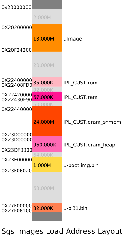
5.3.9.2. Actual Load Addresses
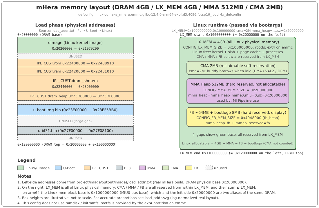
The following are the real load addresses after make image (from project/image/output/images/load_addr.txt):
uImage              0x20200000 - 0x21079200
IPL_CUST.rom        0x22400000 - 0x22408910
IPL_CUST.ram        0x22420000 - 0x22431010
IPL_CUST.dram_shmem 0x22440000 - 0x23D00000    (≈ 24 MB)
IPL_CUST.dram_heap  0x23D00000 - 0x23DF0000
u-boot.img.bin      0x23E00000 - 0x23EF5BB0    (≈ 1 MB)
u-bl31.bin          0x27F00000 - 0x27F08100    (TF-A, provided by the vendor, cannot be modified)
The DRAM physical base address is 0x20000000, and CONFIG_DRAM_SIZE=0x100000000 (4 GB), so all load addresses must fall within [0x20000000, 0x120000000).
The layout diagram is as follows (left: loading stage; right: Linux runtime):
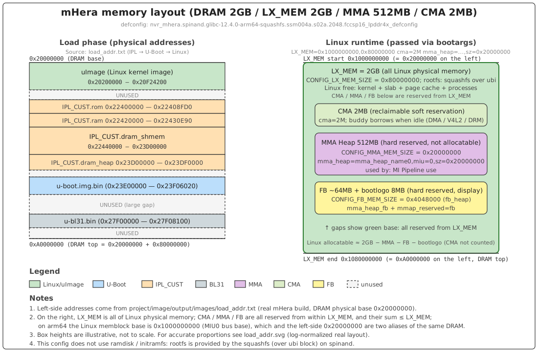
(Reference) spinand 2g layout:
5.3.9.3. Memory Layout Adjustment Method
| Address to change | Where to change |
|---|---|
| uImage load address | The mkimage -a/-e parameters when repacking uImage |
| IPL_CUST segments | IPL defconfig: CONFIG_IPL_CUST_ROM_BASE/LIMIT, CONFIG_IPL_CUST_RAM_BASE, CONFIG_SHMEM_DRAM_BASE/LIMIT, CONFIG_HEAP_DRAM_BASE/LIMIT |
| U-Boot load address | CONFIG_SYS_TEXT_BASE in boot/configs/mhera_comake_d3_emmc_arm64_defconfig (spinand: ..._spinand_arm64_defconfig) |
| BL31 (u-bl31.bin) | Cannot be modified (provided by the vendor; just ensure no overlap with it) |
LX_MEM size |
CONFIG_LX_MEM_SIZE of this defconfig (automatically written to bootargs) |
| MMA Heap size | CONFIG_MMA_MEM_SIZE of this defconfig (automatically written to bootargs mma_heap=...,sz=...) |
| CMA size | CONFIG_CMA_MEM_SIZE of this defconfig (automatically written to bootargs cma=...) |
| FB size | CONFIG_FB_MEM_SIZE of this defconfig |
After the adjustment:
make image will automatically invoke:
project/scripts/parser_loadaddr.py—— parse each image header to obtain the load intervalsproject/scripts/loadaddr_layout_graph.py—— outputload_addr.svgproject/scripts/check_loadaddr.py—— check overlaps / out-of-bounds
Output is located in project/image/output/images/:
load_addr.txt: address list-
load_addr.svg: visualized address regionsload_addr.svg is generated by
loadaddr_layout_graph.py. The USED region is the actual image occupancy, and the gray UNUSED is the hole. After opening the SVG in a browser, hovering the mouse shows the exact size of each segment (decimal / hexadecimal / human-readable).load_addr.txt is the source data of the corresponding SVG.
5.3.9.3.1. load_addr.svg Illustration
load_addr.svg displays (emmc D3 4g):

(Reference) load_addr.svg for the spinand 2g solution:
5.3.9.4. Layout Adjustment Principles
The following principles must be followed when adjusting the memory layout:
- All addresses must fall within
[0x20000000, 0x20000000 + CONFIG_DRAM_SIZE)(in this example[0x20000000, 0x120000000)). - No two USED intervals may overlap during the loading stage (
check_loadaddr.pywill catch this). - The IPL_CUST segments, U-Boot, and uImage must all avoid the area around
0x27F00000occupied by BL31. - MMA, FB and other reserved regions are carved from within LX_MEM; their total must not exceed LX_MEM, and the regions must not overlap.
5.3.9.5. Debugging Method
When an abnormal boot occurs after adjustment:
- Check
project/image/output/images/load_addr.txtandload_addr.svgto confirm there is no overlap / out-of-bounds. -
Check the serial log to locate the issue by stage:
- Hangs before IPL → IPL_CUST segment address has a problem;
- Enters U-Boot but fails to boot Linux → uImage load address or LX_MEM range;
- Linux boots but rootfs mount fails → for emmc check the ext4 partition table; for spinand check
mtdparts/ ubi partition configuration; - Linux boots but MMA initialization fails → check whether the bootargs
mma_heapis consistent withCONFIG_MMA_MEM_SIZE.
-
After Linux boots, check the actual occupancy:
bash
cat /proc/meminfo
cat /proc/mi_modules/mi_sys/mi_sys0
cat /proc/mi_modules/mi_sys_mma/mma_heap_name0
5.3.10. How to adjust partitions?
System partition management is an important part of embedded development. The mHera platform supports flexible partition configuration. You can adjust partition sizes, and add or delete partitions according to actual needs.
5.3.10.1. Storage Media and File System Type Introduction
| Storage Media | Supported Read-Write File System Formats | Supported Read-Only File System Formats |
|---|---|---|
| spi nand | ubifs, lfs, fwfs | squashfs |
| eMMC | ext4 | squashfs |
5.3.10.2. Partition Table Description
| Partition | Description |
|---|---|
| BOOT | Boot image partition (IPL/IPL_CUST/U‑Boot/TEE) |
| BOOT_BAK | Backup partition of BOOT |
| ENV | Environment variable partition |
| ENV1 | ENV backup partition |
| KERNEL | Linux kernel image partition |
| KERNEL_BACKUP | KERNEL backup partition |
| rootfs | Root file system partition |
| MISC | Configuration file partition (panel parameters, etc.) |
| ubia | Includes two partitions: miservice and customer. miservice is the SDK service partition (ko, so, IQ files, etc.), and customer is the customer-defined partition |
5.3.10.3. Partition Configuration File
The partition configuration script is located at:
You can find the currently used partition configuration file through the IMAGE_CONFIG variable in the defconfig.
5.3.10.4. Modifying Partition Size
1. Find the corresponding partition configuration variable
Each partition is defined by a set of variables, for example the customer partition:
# customer
customer$(RESOURCE)             =       $(OUTPUTDIR)/customer
customer$(FSTYPE)               =       ubifs
customer$(IMAGE)                =       customer.ubifs
customer$(UBIVOLID)             =       1
ifneq ($(DEBUG), )
customer$(PATSIZE)              =       0x4500000
else
customer$(PATSIZE)              =       0x5000000
endif
customer$(MOUNTTG)              =       /customer
customer$(MOUNTPT)              =       ubi0:customer
customer$(UBIPART)              =       ubia
customer$(OTABLK)               =       /dev/ubi0_1
2. Modify the partition size
Modify the xxx$(PATSIZE) variable to adjust the partition size:
3. Verify the partition size
After modification, rebuild and check whether the partition size overflows in project/image/output/images/partition_layout.txt.
5.3.10.5. Adding a Custom Partition
Step 1: Define the new partition variables
# Add a new myapp partition with a size of 3MB. If the size is exceeded, the excess size needs to be subtracted from other partitions.
# myapp
myapp$(RESOURCE)                =       $(OUTPUTDIR)/myapp
myapp$(FSTYPE)                  =       ubifs
myapp$(IMAGE)                   =       myapp.ubifs
myapp$(PATSIZE)                 =       0x300000
myapp$(UBIVOLID)                =       2
myapp$(MOUNTTG)                 =       /myapp
myapp$(MOUNTPT)                 =       ubi0:myapp
myapp$(UBIPART)                 =       ubia
myapp$(OTABLK)                  =       /dev/ubi0_2
Step 2: Add to the build list
Step 3: Add the file copy logic
Add the logic for copying files to $(OUTPUT)/myapp in the Makefile.
5.3.10.6. Deleting a Partition
Perform the reverse of the partition addition operation:
- Remove the partition name from
IMAGE_LISTandUSR_MOUNT_BLOCKS - Delete the partition variable definitions
- Delete the file copy logic for
$(OUTPUT)/myappadded in the Makefile.
5.3.10.7. Advanced Reference
mHera also supports backup partitions and AB partitions. Please refer to:
- Detailed partition configuration documentation: System Partitions
5.3.11. How to Enter the U-Boot Terminal
If the kernel has already been flashed, press and hold the enter key before power-on; after booting, it will enter the U‑Boot terminal.
If the kernel has not been flashed, powering on will automatically enter the U‑Boot terminal, and the log will print as follows:
SP16 NTC16G LPDDR4X 3200
miu pll: 466MHz
MRR read zero
ddr train finish
SHMEM@relocate 0xa0016100->0x22440000
HEAP@re-init 0x23d00000~0x23df0000
*** Warning - readenv() failed, using default environment

RECORD@moving tc from 0xa0015ae8 to 0x20002000 count:1
IMG_READ@devs:0x2 img:TF_A bak:0 ofs:0x0 sz:0x580 dst:0x23d00000
IMG_READ@devs:0x2 img:TF_A bak:0 ofs:0x0 sz:0x8140 dst:0x27efffc0
IMG_VERIFY@TF_A
IMG_DECOMP@0 from 0x27f00000 to 0x27f00000
IMG_READ@devs:0x2 img:IPL_CUST bak:0 ofs:0x0 sz:0x580 dst:0x23d00580
IMG_READ@devs:0x2 img:IPL_CUST bak:0 ofs:0x0 sz:0x8fc0 dst:0x22400000
IMG_VERIFY@IPL_CUST
IMG_DECOMP@0 from 0x22400000 to 0x22400000
Flashing D-Cache and Disabling MMU
OS_JUMP@method:2(0x27f00000)
NOTICE:  Mhera bl31_setup
NOTICE:  BL31: v2.5(release):v2.5-114-gc3988ee
NOTICE:  BL31: Built : 12:31:23, Mar 12 2026

IPL_CUST 3f84974
D-0
SHMEM@at 0x22440000~0x23d00000
HEAP@init 0x23d00000~0x23df0000
IMG_READ@devs:0x2 img:UBOOT bak:0 ofs:0x0 sz:0x580 dst:0x23d00000
IMG_READ@devs:0x2 img:UBOOT bak:0 ofs:0x0 sz:0x5253c dst:0x22545140
IMG_VERIFY@UBOOT
IMG_DECOMP@2 from 0x22545180 to 0x23e00000
Flashing D-Cache and Disabling MMU
OS_JUMP@method:2(0x23e00000)


U-Boot 2021.10 (Apr 24 2026 - 11:19:06 +0800)

SoC: Sgs mhera
Model: MHERA
Version: M###g1aca0d3
DRAM:  510 MiB
[Padmux]reset PAD16(reg 0x153400:5c; mask0x1) t0 MIPITX_OUT_MODE_1 (org: MIPITX_OUT_MODE_2)
[Padmux]reset PAD17(reg 0x153400:5c; mask0x100) t0 MIPITX_OUT_MODE_1 (org: MIPITX_OUT_MODE_2)
[Padmux]reset PAD18(reg 0x153400:5c; mask0x2) t0 MIPITX_OUT_MODE_1 (org: MIPITX_OUT_MODE_2)
[Padmux]reset PAD19(reg 0x153400:5c; mask0x200) t0 MIPITX_OUT_MODE_1 (org: MIPITX_OUT_MODE_2)
[Padmux]reset PAD20(reg 0x153400:5c; mask0x4) t0 MIPITX_OUT_MODE_1 (org: MIPITX_OUT_MODE_2)
[Padmux]reset PAD21(reg 0x153400:5c; mask0x400) t0 MIPITX_OUT_MODE_1 (org: MIPITX_OUT_MODE_2)
[Padmux]reset PAD22(reg 0x153400:5c; mask0x8) t0 MIPITX_OUT_MODE_1 (org: MIPITX_OUT_MODE_2)
[Padmux]reset PAD23(reg 0x153400:5c; mask0x800) t0 MIPITX_OUT_MODE_1 (org: MIPITX_OUT_MODE_2)
WDT:   Not found!
NAND:  SPI 54M
[SPINAND] RFC use command 0x6b
[SPINAND] dummy clock 0x8
[SPINAND] Program with command 0x32
[SPINAND] Random with command 0x34
[FLASH] BDMA mode.
[FLASH] spinand init done!
spi clk already initialized
[FLASH] dev_id = 0xee
[FLASH] mfr_id = 0xc8, dev_id= 0x91 id_len = 0x2
128 MiB
MMC:   Fail to get pad(0x2000f) ip(0x0_8)  form padmux !
MSC: 1, MSC: 0
Loading Environment from NAND...
ENV: offset = 0x500000 size = 0x40000
ENV1: offset = 0x540000 size = 0x40000
*** Warning - bad CRC, using default environment

In:    serial
Out:   serial
Err:   serial
Net:   eth0: gmac0
5.4. BSP-Related Issues
5.4.1. How to Modify GPIO Configuration?
GPIO (General Purpose Input Output) pins are important peripheral interfaces in embedded systems.
5.4.1.1. GPIO Basics
GPIO Index and PAD Correspondence
The GPIO Pad Name on the schematic must be converted to a GPIO Index before it can be used in software. For example: PAD_SPI_DO corresponds to GPIO Index 39.
Partial correspondence table of common PADs and GPIO Index (for the complete table, please refer to kernel/drivers/sgs_common/gpio/hal/mhera/pub/gpio.h):
| Pad Name | GPIO Index | Pad Name | GPIO Index |
|---|---|---|---|
| PAD_SD0_D0 | 65 | PAD_SD0_D1 | 64 |
| PAD_SPI_DO | 39 | PAD_PWM0 | 72 |
| PAD_GPIO17 | 5 | PAD_GPIO18 | 6 |
| PAD_I2C1_SCL | 11 | PAD_I2C1_SDA | 12 |
5.4.1.2. U-Boot Stage Configuration
1. U-Boot menuconfig configuration
Configuration options:
CONFIG_SGS_GPIO=y
CONFIG_SGS_PADMUX=y
CONFIG_SGS_PAD_INIT=n # Pin initial state setting
2. DTS configuration
Configure the GPIO node in the U-Boot dts file. The dts location is {SourceCode}/boot/arch/arm/dts/mhera.dtsi:
3. U-Boot command-line operation
You can directly operate GPIO in the U-Boot command line:
| Command | Description | Example |
|---|---|---|
gpio input <gpio#> |
Set GPIO to input mode | gpio input 69 |
gpio set <gpio#> |
Set GPIO to output high level | gpio set 10 |
gpio clear <gpio#> |
Set GPIO to output low level | gpio clear 49 |
gpio toggle <gpio#> |
Toggle GPIO level | gpio toggle 49 |
gpio status <gpio#> |
View GPIO status | gpio status 20 |
5.4.1.3. Kernel Stage Configuration
1. Kernel menuconfig configuration
Configuration options:
CONFIG_GPIO_SYSFS=y
CONFIG_MSYS_GPIO=n
CONFIG_SGS_GPIO=y
CONFIG_SGS_PADMUX=y
CONFIG_SGS_PAD_INIT=n # Pin initial state setting
2. DTS configuration
Configure the GPIO node in the Kernel dts file. The dts location is {SourceCode}/kernel/arch/arm/boot/dts/mhera.dtsi:
5.4.1.4. Pin Multiplexing Function Configuration (Padmux)
When you need to use the multiplexing function of GPIO (such as I2C, SPI, PWM, etc.), you need to configure it in the {SourceCode}/kernel/arch/arm/boot/dts/xxx-padmux.dtsi file.
Configuration format:
Configuration example (I2C0):
<PAD_HDMITX_SCL    PINMUX_FOR_I2C0_MODE_1    PINMUX_FOR_I2C0_MODE_1>,
<PAD_HDMITX_SDA    PINMUX_FOR_I2C0_MODE_1    MDRV_PUSE_I2C0_SDA>,
Configuration example (GPIO mode):
Configuration notes:
- A Pad can only be configured with one Mode and cannot have multiple Modes configured at the same time.
- One MDRV_PUSE_XXX can only correspond to one group of Pad configurations and cannot be reused.
- The configured Pad and Mode must match (refer to
drivers/sgs/include/mhera/padmux.h). - Direct multiplexing operations in the driver are not allowed; configure them uniformly in padmux.dtsi.
5.4.1.5. Pin Initial State Setting
Configure the initial state of the pin in xxx-padmux.dtsi, including input/output direction, level state, internal pull state, and drive strength level.
Configuration format:
/*
 * Format:
 * <Pad_Index   Direction       Level_State        Pull_State          Driving_Level>
 */
<PAD_GPIO0       GPIO_DIR_OUT    GPIO_LEVEL_HIGH   PAD_PULL_UP         PAD_DRV_1>,
<PAD_I2C0_SDA    GPIO_DIR_IN     GPIO_LEVEL_NA     PAD_PULL_DEFAULT    PAD_DRV_DEFAULT>,
Parameter description:
| Parameter | Optional Values | Description |
|---|---|---|
| Direction | GPIO_DIR_IN, GPIO_DIR_OUT, GPIO_DIR_NA | Input/Output/Not set |
| Level_State | GPIO_LEVEL_HIGH, GPIO_LEVEL_LOW, GPIO_LEVEL_NA | High level/Low level/Not set |
| Pull_State | PAD_PULL_UP, PAD_PULL_DOWN, PAD_HIZ, PAD_PULL_DEFAULT | Pull-up/Pull-down/Floating/Default |
| Driving_Level | PAD_DRV_0~PAD_DRV_8, PAD_DRV_DEFAULT | Drive strength level 0~8 |
5.4.1.6. Operating GPIO in User Space
Operate GPIO in user space through the sysfs interface:
1. Export the GPIO pin
2. Set the direction
# Set as output
echo out > /sys/class/gpio/gpio12/direction
# Set as input
echo in > /sys/class/gpio/gpio12/direction
3. Read/Write the level
# Read the level
cat /sys/class/gpio/gpio12/value
# Set high level
echo 1 > /sys/class/gpio/gpio12/value
# Set low level
echo 0 > /sys/class/gpio/gpio12/value
4. Configure pull-up/pull-down
# Set pull-up (must be set to input first)
echo 12 up > /sys/class/sgs/msys/gpio_pull
# Set pull-down
echo 12 down > /sys/class/sgs/msys/gpio_pull
5. Configure drive strength
5.4.1.7. Debugging Method
1. Quick verification with U-Boot commands
Verify pin functions using the gpio command at the U-Boot stage:
2. Verification with the sysfs interface
Verify using sysfs while Linux is running:
# Export and test
echo 61 > /sys/class/gpio/export
echo out > /sys/class/gpio/gpio61/direction
echo 1 > /sys/class/gpio/gpio61/value
cat /sys/class/gpio/gpio61/value
3. Check Padmux configuration conflicts
Use the iocheck tool (after make kernel, the prog_io_check tool will be generated under kernel/drivers/sgs_common/gpio/ut/io_check; you can copy the tool to the board's customer directory) to check whether the padmux configuration is correct:
# Assume the prog_io_check tool is under the customer path
cd /customer
# Query the current multiplexing of a GPIO
prog_io_check -i 61
# Set to a specified mode
prog_io_check -i 61 -m mode_index -s
# Verify padmux mode conflicts
prog_io_check -v
4. Common problem troubleshooting
| Problem | Troubleshooting Method |
|---|---|
| GPIO cannot be pulled high/low | Use a multimeter to directly measure the pin voltage and check the hardware connection |
| Padmux abnormal | Use the iocheck tool to check the padmux configuration and check for conflicts |
| Pull-up/pull-down does not take effect | Ensure the GPIO has been set to input mode; pull-up/pull-down cannot be measured in output mode |
5.4.1.8. Driver Development API Reference
The following APIs can be used to operate GPIO in driver code:
#include <drv_gpio.h>

// Request and free GPIO
gpio_request(gpio_index, "test");
gpio_free(gpio_index);

// Set direction
gpio_direction_input(gpio_index);
gpio_direction_output(gpio_index, value);

// Read/Write level
value = gpio_get_value(gpio_index);
gpio_set_value(gpio_index, 1);

// Set pull-up/pull-down
drv_gpio_pull_up(gpio_index);
drv_gpio_pull_down(gpio_index);
drv_gpio_pull_off(gpio_index);

// Set drive strength
drv_gpio_drv_set(gpio_index, level);
5.4.1.9. Reference Materials
For detailed GPIO usage instructions, please refer to: GPIO Usage Reference
If you want to know about GPIO register configuration and drive strength, please refer to the HW Checklist table provided by the hardware team.
5.4.2. SD card is not detected after insertion?
1. U‑Boot
U‑Boot command to view SD card contents
If an error is reported, check whether the SDMMC driver is enabled in the U‑Boot config. The CONFIG_UBOOT_CONFIG configuration item in the defconfig is the corresponding U‑Boot config.
CONFIG_CMD_SGS_MMC=y
CONFIG_CMD_SGS_MMC_FDISK=y
2. kernel
Enable the SDMMC driver in the kernel config. The CONFIG_KERNEL_CONFIG configuration item in the defconfig is the corresponding KERNEL config.
CONFIG_SGS_SDMMC=m
5.4.3. How to Adjust USB Drive Strength?
Reference: USB Usage Reference
5.4.4. How to Use the RNDIS Function?
RNDIS (Remote Network Driver Interface Specification) is a network protocol defined by Microsoft based on USB, which can be used to implement network communication between the development board and the PC via a USB cable.
Note: Using RNDIS will cause USB WIFI to be unusable!
5.4.4.1. Kernel Configuration
1. Configure USB macros to support RNDIS
Enable the following configurations in the kernel menuconfig:
CONFIG_USB_DWC3_GADGET=y
CONFIG_USB_GADGET=m
CONFIG_USB_CONFIGFS=m
CONFIG_USB_CONFIGFS_RNDIS=y
CONFIG_USB_CONFIGFS_MASS_STORAGE=y
CONFIG_USB_ETH=m
CONFIG_USB_MASS_STORAGE=m
CONFIG_USB_MASS_STORAGE=m
# CONFIG_TYPEC is not set
2. Modify dts to set usb to peripheral
diff --git a/arch/arm/boot/dts/mhera.dtsi b/arch/arm/boot/dts/mhera.dtsi
index 8458b82..340b6cd 100644
--- a/arch/arm/boot/dts/mhera.dtsi
+++ b/arch/arm/boot/dts/mhera.dtsi
@@ -2069,7 +2069,7 @@
             status = "okay";

             dwc3_p3: dwc3 {
-                dr_mode = "host";   /* host or peripheral */
+                dr_mode = "peripheral";   /* host or peripheral */
                 compatible = "snps,dwc3";
                 reg = <0x0 0x1f348000 0x1400>;
                 maximum-speed = "super-speed";
3. Add KO to kernel_mod_list
Add the following ko in order to {SourceCode}/project/kbuild/customize/{kernel_version}/{chip}/{product}/kernel_mod_list
usb-common.ko
usbcore.ko
sgs_usb3_phy.ko
udc-core.ko
dwc3.ko
sgs_dwc3_of_simple.ko
libcomposite.ko

u_ether.ko
usb_f_ecm.ko
usb_f_ecm_subset.ko
usb_f_rndis.ko
g_ether.ko
4. Build and flash the firmware
After the build completes, a firmware image containing RNDIS support will be generated. Flash it to the development board.
5.4.4.2. Confirm the KO Modules
After the system boots, confirm that the following RNDIS-related driver modules have been loaded:
You should see output similar to the following:
usb_f_rndis            24576  2 g_ether
usb_f_ecm_subset       16384  0
usb_f_ecm              16384  1
u_ether                24576  4 g_ether,usb_f_rndis,usb_f_ecm_subset,usb_f_ecm
usbhid                 24576  0
usb_storage            53248  0
udc_msb250x            32768  0
libcomposite           53248  4 g_ether,usb_f_rndis,usb_f_ecm_subset,usb_f_ecm
udc_core               32768  6 usb_f_rndis,usb_f_ecm,u_ether,udc_msb250x,libcomposite,dwc3
sgs_usb3_phy           49152  3
sgs_usb2_phy           32768  2
usbcore               204800  5 usbhid,usb_storage,xhci_plat_hcd,xhci_hcd,ehci_hcd
usb_common             20480 10 udc_msb250x,libcomposite,xhci_plat_hcd,xhci_hcd,sgs_dwc3_of_simple,dwc3,udc_core,sgs_usb3_phy,sgs_usb2_phy,usbcore
5.4.4.3. Board-Side Verification Method
1. Confirm the USB network adapter exists
You should be able to see the usb0 network adapter.
2. Bring up the USB network adapter
3. Configure the IP address
Note: Only after executing
ifconfig usb0 upcan the PC recognize the RNDIS network device.
5.4.4.4. PC-Side IP Address Configuration
Find the Ethernet device (USB Ethernet/RNDIS Gadget) in the PC's network devices, and set an IP address in the same network segment as the board, for example 192.168.1.100.
5.4.5. How to Use an NFS File System?
- Default NFS configuration is already enabled
-
Enable the NFS service on the PC side
The files to be mounted must have read/write permissions for everyone
-
NFS mount command on the board side
# Get the IP address 192.168.1.123 of the PC
mount -t nfs -o nolock 192.168.1.123:/share /mnt
5.4.6. How to Modify the Serial Port Baud Rate?
The default serial port baud rate is 115200.
-
U‑Boot
Adjust CONFIG_BAUDRATE in
boot/include/configs/{chip}.hto the specified baud rate -
kernel
Adjust the baud rate in bootargs. The file location is:
kernel/arch/arm/boot/dts/xxx.dts
5.5. Model Zoo
Model Zoo is a collection of IPU model examples and conversion scripts, oriented toward AI model deployment and application development running on the IPU, designed to help developers quickly get started with the IPU and quickly run through the model inference process.
For details, please refer to: https://git.sigmastar.com.cn:9090/sigmastar/sgs_model_zoo
5.6. How to Replace the flash?
5.7. How to Use Secure Boot?
Security Boot (Secure Boot) is the first security verification process executed after the system is powered on. Its core goal is to ensure the integrity, authenticity, and legitimacy of all executed code (firmware, bootloaders, kernels, etc.) throughout the entire chain from hardware boot to operating system loading, preventing malicious code (such as viruses, tampered firmware) from being injected or replaced. It blocks security threats from the boot source and protects the operational security of the device.
Secure boot code path: {SourceCode}/project/image/security_boot_tools
Secure boot documentation path: Security Boot Usage Reference and Security Boot Manual Signing Usage Reference
There are two core tasks in using Security Boot: manually signing the image files (or encrypting + signing), and burning the corresponding keys used for signing (or encrypting + signing) into the chip OTP.
Taking RSA2048 and AES128 as examples:
5.7.1. Generate Keys
5.7.1.1. Create an RSA Key
RSA is mainly used for firmware signing to prevent malicious firmware tampering. Using the RSA2048 algorithm, you need to generate RSA private.pem and public.pem.
The E key value generated by the following commands defaults to 0x10001. The security boot flow does not support a custom E key value.
RSA2048 :
-
Generate an RSA2048 private key
openssl genrsa -out private.pem 2048 -
Generate an RSA2048 public key
openssl rsa -in private.pem -out public.pem -outform PEM -pubout
5.7.1.2. Create an AES Key
AES is used to encrypt firmware. Here, the xxd tool is used to generate an AES key binary file. This method is applicable to the 8 aes-128 keys or 4 aes-256 keys in the OTP. According to your needs, multiple images can use the same aes key, or multiple images can use different aes keys.
AES-128 Key
5.7.2. Burn the OTP Fields
The method to burn the OTP fields is to use the SGS U‑Boot optpctrl Command. U‑Boot must have CONFIG_ARM_SMCCC enabled, otherwise the otpctrl command cannot perform read/write operations. First, build and flash a normal unsigned and unencrypted image to the SOC.
Enter U‑Boot and use the U‑Boot Command otpctrl to burn OTP_SECURITY_BOOT, the LOCK and BLOCK of the RSA KEY, OTP_ROM_SELECT_AES_KEY, etc.
Note
- OTP can only be written once. Once written, it cannot be cleared or rewritten. To prevent misoperation causing the system to fail to boot or even the IC to be scrapped, it is generally recommended to debug in Debug mode until it passes, and then perform the formal OTP process.
- Difference between Debug mode and formal mode:
- Hardware: Debug mode does not burn the OTP_SECURITY_BOOT field; formal mode needs to burn the OTP_SECURITY_BOOT field.
- Software: In Debug mode, Security_boot_tools sets the AUTH field in the IPL header to 1, and the rom code loading IPL, IPL loading IPL_CUST/TF-A/OPTEE, and IPL_CUST loading LINUX will decide whether to go through the signature verification boot flow based on the AUTH flag. In formal mode, the rom code loading IPL, IPL loading IPL_CUST/TF-A/OPTEE, and IPL_CUST loading LINUX will decide whether to go through the signature verification boot flow based on whether OTP has burned the OTP_SECURITY_BOOT flag.
For the meaning of each parameter, refer to Security Boot Usage Reference
Based on the public RSA2048 and AES128, taking Debug mode as an example:
####### RSA N-Key ########
otpctrl -w 0x0 0x0 0x083692f7;otpctrl -w 0x0 0x4 0x767a3811;otpctrl -w 0x0 0x8 0xee760a12;otpctrl -w 0x0 0xc 0x36981e3f;otpctrl -w 0x0 0x10 0x567d7c80;otpctrl -w 0x0 0x14 0x5386d79a;otpctrl -w 0x0 0x18 0xb30c364c;otpctrl -w 0x0 0x1c 0x0509b6ec;otpctrl -w 0x0 0x20 0x2d5b7fba;otpctrl -w 0x0 0x24 0x603faaa9;otpctrl -w 0x0 0x28 0xf6001bff;otpctrl -w 0x0 0x2c 0x65f24742;otpctrl -w 0x0 0x30 0xea1eb046;otpctrl -w 0x0 0x34 0x8279db13;otpctrl -w 0x0 0x38 0xfcda08f2;otpctrl -w 0x0 0x3c 0x7945946b;
otpctrl -w 0x0 0x40 0x5ab90d76;otpctrl -w 0x0 0x44 0xa62381c8;otpctrl -w 0x0 0x48 0xcfe07b8d;otpctrl -w 0x0 0x4c 0xd060c666;otpctrl -w 0x0 0x50 0x8934ad74;otpctrl -w 0x0 0x54 0x6e7b524b;otpctrl -w 0x0 0x58 0xd158d907;otpctrl -w 0x0 0x5c 0x4fbe917b;otpctrl -w 0x0 0x60 0x234cd758;otpctrl -w 0x0 0x64 0x6cc50b4f;otpctrl -w 0x0 0x68 0xd2a4c9ae;otpctrl -w 0x0 0x6c 0x92c7ef0c;otpctrl -w 0x0 0x70 0x839adec4;otpctrl -w 0x0 0x74 0x0cdd9bba;otpctrl -w 0x0 0x78 0xb2525bc1;otpctrl -w 0x0 0x7c 0x59b47c13;
otpctrl -w 0x0 0x80 0x438a1be1;otpctrl -w 0x0 0x84 0xd2e85ab1;otpctrl -w 0x0 0x88 0xc4c83dce;otpctrl -w 0x0 0x8c 0x606841ea;otpctrl -w 0x0 0x90 0x71dc495e;otpctrl -w 0x0 0x94 0xb0f26ac1;otpctrl -w 0x0 0x98 0xf8beac9b;otpctrl -w 0x0 0x9c 0x353c787f;otpctrl -w 0x0 0xa0 0xea55a5cf;otpctrl -w 0x0 0xa4 0xf7f8e4cd;otpctrl -w 0x0 0xa8 0x87f3fb58;otpctrl -w 0x0 0xac 0x6f3032b0;otpctrl -w 0x0 0xb0 0x7dba24a5;otpctrl -w 0x0 0xb4 0x7866ae54;otpctrl -w 0x0 0xb8 0xbdb3e5dd;otpctrl -w 0x0 0xbc 0x40c58158;
otpctrl -w 0x0 0xc0 0x7c3eadcc;otpctrl -w 0x0 0xc4 0xd93922e9;otpctrl -w 0x0 0xc8 0xc3cdaa7b;otpctrl -w 0x0 0xcc 0xfadfcd0d;otpctrl -w 0x0 0xd0 0xbb82dac5;otpctrl -w 0x0 0xd4 0x83d259a8;otpctrl -w 0x0 0xd8 0x99025f3c;otpctrl -w 0x0 0xdc 0x2de1b36a;otpctrl -w 0x0 0xe0 0xfe7c22c8;otpctrl -w 0x0 0xe4 0x15bb8c06;otpctrl -w 0x0 0xe8 0x4b975ff2;otpctrl -w 0x0 0xec 0xa91031eb;otpctrl -w 0x0 0xf0 0x8bfadaf0;otpctrl -w 0x0 0xf4 0x355b52e4;otpctrl -w 0x0 0xf8 0xfc4ac084;otpctrl -w 0x0 0xfc 0xcc317580;
####### RSA E-Key ########
otpctrl -w 0x1 0x0 0x00010001
# AES128_key1
otpctrl -w 0x5 0x0 0x03020100;otpctrl -w 0x5 0x4 0x07060504;otpctrl -w 0x5 0x8 0x0B0A0908;otpctrl -w 0x5 0xC 0x0F0E0D0C;
Reading with otpctrl -r 0x5 returns the following data, indicating the AES key was successfully written:
[OTP ATF-32] operation = R, cmd = 5, off = 0, data = 0

Results:

0x00, 0x01, 0x02, 0x03, 0x04, 0x05, 0x06, 0x07, 0x08, 0x09, 0x0a, 0x0b, 0x0c, 0x0d, 0x0e, 0x0f,
5.7.3. Set OTP to Use aesKey128_1 for Encryption
otpctrl -w 0x24 0x0 0xFF000000
Reading with otpctrl -r 0x24 returns the following data, indicating a successful write:
[OTP ATF-32] operation = R, cmd = 24, off = 0, data = 0

Results:

0x00, 0x00, 0x00, 0xff,
5.7.4. Copy Keys to the Specified Path
-
Copy the RSA key
Replace the key binary files that need to be used under the corresponding rsa2048 directory under project/image/security_boot_tools/ with the n pairs of RSA keys generated above.
-
Copy the AES key
Replace the corresponding aesKey128_1.bin file under the aesKey directory under project/image/security_boot_tools/ with the aesKey_128.bin generated above.
5.7.5. Configuration File sign_image.config
After burning the OTP, the next step is to create the signed + encrypted image. In an environment where a normal unsigned + unencrypted image has already been generated, enter project/image/security_boot_tools/ and modify the sign_image.config file.
sw_debug=1        # Set to 1 means that even if the OTP_SECURITY_BOOT field is not burned in the OTP, the system boot process will still go through the security boot signature verification and decryption flow.
ipl_aeskeynum=1   # The IPL will use security_boot_tools/aeskey/aesKey128_1.bin as the aes-key for encryption.
ipl_aeskeylen=128 # There are 8 aes128 keys and 4 aes256 keys under the aeskey directory. The value of aeskeylen is 128 or 256. Used together with ipl_aeskeynum.
5.7.6. Generate the Security Image
After modifying sign_image.config, build the encrypted + signed image. Execute under project/image/security_boot_tools/:
The generated images are in: security_boot_tools/image_secure
Generate the firmware for USB upgrade:
The generated firmware is in: security_boot_tools/image_secure/SgsUsbImage_xxx.bin
5.7.7. Check the System Print
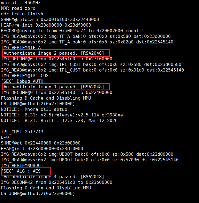
Check the system prints to confirm that ROM->IPL->IPL_CUST->U-Boot has entered the SecurityBoot flow.
How to confirm whether ROM->IPL goes through SecurityBoot:
ROM will not print any log on successful IPL signature verification, but will print AUTH ERR on verification failure (the baud rate may need to be set to 115200, otherwise it will be garbled).
How to confirm whether IPL->IPL_CUST->U-Boot goes through SecurityBoot:
Just check the log. It generally contains the Authenticate image keyword. If the decryption flow is enabled, there will also be the AES ECB keyword.
For example:
How to confirm whether U-Boot -> kernel goes through SecurityBoot:
Check whether the bootcmd contains the sigauth field.
5.7.8. How to Manually Sign Your Own System Image
The previous operations all rely on a pre-built SDK image package. If it is your own system image, please refer to Security Boot Manual Signing Usage Reference
5.7.9 Thermal Control
Main Temperature Points
| Temperature Point | Threshold | Description |
|---|---|---|
| Throttling Temperature | 115°C | Automatically throttles when exceeded |
| Shutdown Temperature | 125°C | Emergency shutdown when exceeded |
View the throttling temperature threshold:
View the shutdown temperature threshold:
Setting Temperature Points
Set the throttling temperature threshold (e.g., 85000):
Set the shutdown temperature threshold (e.g., 105000):
After enabling 1.7GHz or 1.8GHz, the CPU requires a lower junction temperature, which must not exceed 95°C (requiring better cooling measures), and the service life will be significantly reduced.
Next step: Learn more about the "Development" documentation