Sgs Spinand Debug SOP Manual
REVISION HISTORY
| Revision No. | Description |
Date |
|---|---|---|
| 1.0 | 03/05/2024 |
Issue 1. SPI NAND Flash ESTAR Upgrade Failure
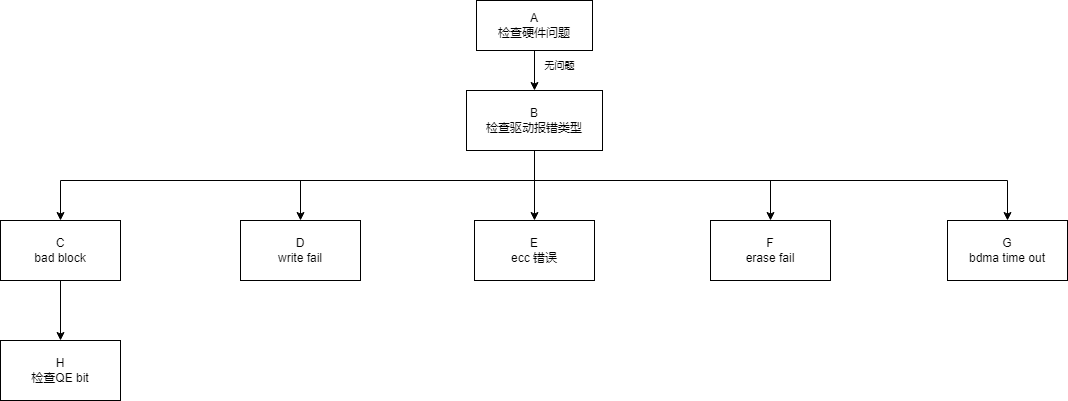
| Step | Method | Exit Condition | Next Step | Materials Required for SWRD | Related FAQ |
|---|---|---|---|---|---|
| A | 1. Check for cold solder joints on SoC chip 2. Check for cold solder joints on Flash chip 3. Verify Flash voltage matches datasheet specifications 4. Check if waveforms are synchronized between SoC and Flash pins |
Exit Condition 1: ESTAR still fails after hardware rework Exit Condition 2: ESTAR fails after adjusting pad driving Exit Condition 3: ESTAR succeeds |
Exit Condition 1: >B Exit Condition 2: >B Exit Condition 3: ==>End of process |
||
| B | Confirm log information: 1. bad block error 2. p fail, program data error 3. -74 ecc err, ECC error 4. e fail, erase error 5. "bdma time out" message |
Exit Condition 1: ESTAR fails due to bad blocks Exit Condition 2: ESTAR fails due to program data error Exit Condition 3: ESTAR fails due to ECC error Exit Condition 4: Upgrade fails due to erase error Exit Condition 5: ESTAR fails due to BDMA timeout Exit Condition 6: "flash size is 0" or "partition size is no enough" message |
Exit Condition 1: >C Exit Condition 2: >D Exit Condition 3: >E Exit Condition 4: >F Exit Condition 5: >G Exit Condition 6: >Contact RD for confirmation |
Full upgrade image package | |
| C | Verify with vendor if bad block count is within acceptable range | Exit Condition 1: Bad block count is unreasonable Exit Condition 2: Bad block count is reasonable |
Exit Condition 1: ==>H Exit Condition 2: End of process |
1. Branch information 2. Build config 3. Branch information 4. Reproduction steps on reference board 5. Flash datasheet |
|
| D | 1. Check if Flash register p fail bit is set 2. Check if Flash register write protection bit is set |
Exit Condition 1: Flash register p fail bit is set Exit Condition 2: Flash register write protection bit is set Exit Condition 3: Both Flash register p fail bit and write protection bits are 0 |
Exit Condition 1: >Contact vendor to confirm p fail cause Exit Condition 2: >End of process, contact RD Exit Condition 3: ==>End of process, contact RD |
1. Branch information 2. Build config 3. Branch information 4. Reproduction steps on reference board 5. Flash datasheet 6. Provide register status screenshot |
|
| E | Identify the page where ECC error occurs, use read command in U-Boot to read that page data separately, and use ISP tool to read Flash ECC-related register status | Exit Condition 1: Flash register reports ECC error Exit Condition 2: Flash register does not report ECC error |
Exit Condition 1: >Confirm ECC with vendor first, then contact RD after clarification Exit Condition 2: >End of process, contact RD |
1. Branch information 2. Build config 3. Branch information 4. Reproduction steps on reference board 5. Flash datasheet 6. Provide register status screenshot |
|
| F | 1. Check if Flash register e fail bit is set 2. Check if Flash register write protection bit is set |
Exit Condition 1: Flash register e fail bit is set Exit Condition 2: Flash register write protection bit is set Exit Condition 3: Both Flash register e fail bit and write protection bits are 0 |
Exit Condition 1: >Contact vendor to confirm e fail cause Exit Condition 2: >End of process, contact RD Exit Condition 3: ==>End of process, contact RD |
1. Branch information 2. Build config 3. Branch information 4. Reproduction steps on reference board 5. Flash datasheet 6. Provide register status screenshot |
|
| G | Check BDMA register status | N/A | N/A | 1. Branch information 2. Build config 3. Branch information 4. Reproduction steps on reference board 5. BDMA register information 6. Flash datasheet |
|
| H | Check SNI or code for current Flash QE bit configuration status | Exit Condition 1: QE bit is not configured correctly Exit Condition 2: QE bit is configured correctly |
Exit Condition 1: >Configure QE bit according to datasheet, end of process Exit Condition 2: >Contact RD, end of process |
1. Branch information 2. Build config 3. Branch information 4. Reproduction steps on reference board 5. Flash datasheet |
Issue 2. SPI NAND Backup Partition Boot Failure
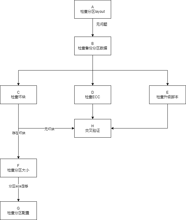
| Step | Method | Exit Condition | Next Step | Materials Required for SWRD | Related FAQ |
|---|---|---|---|---|---|
| A | Use ISP tool to dump data and check if partition information contains backup partition info | Exit Condition 1: Backup partition info exists Exit Condition 2: No backup partition info |
Exit Condition 1: >B Exit Condition 2: >Add backup partition |
||
| B | Use ISP tool or nand read command in U-Boot to dump backup partition data and compare with source file | Exit Condition 1: Backup partition data partially mismatches with entire block offset Exit Condition 2: Backup partition data has partial byte errors Exit Condition 3: Backup partition data does not match source file and data is disordered Exit Condition 4: Backup partition data is correct |
Exit Condition 1: >C Exit Condition 2: >D Exit Condition 3: >E Exit Condition 4: >End of process, contact RD |
1. Branch information 2. Build config 3. Branch information 4. Reproduction steps on reference board 5. Flash datasheet |
|
| C | Check bad block count in backup partition | Exit Condition 1: Few bad blocks exist Exit Condition 2: No bad blocks |
Exit Condition 1: >F Exit Condition 2: >H |
||
| D | Check if ECC error occurs in backup partition, RD assistance may be requested for this step | Exit Condition 1: ECC error exists Exit Condition 2: No ECC error |
Exit Condition 1: >Erase backup partition and re-upgrade Exit Condition 2: >H |
||
| E | Check if upgrade script performs data upgrade on backup partition | Exit Condition 1: Upgrade script does not upgrade backup partition Exit Condition 2: Upgrade script upgrades backup partition |
Exit Condition 1: >Add backup partition upgrade commands Exit Condition 2: >H |
||
| F | Calculate if actual bin file size plus bad block size exceeds partition size | Exit Condition 1: Exceeds partition size Exit Condition 2: Does not exceed partition size |
Exit Condition 1: >G Exit Condition 2: >End of process, contact RD |
1. Branch information 2. Build config 3. Branch information 4. Reproduction steps on reference board 5. Flash datasheet |
|
| G | Check if allowed bad block count in image config matches actual bad block count in current partition | Exit Condition 1: Allowed bad block count is greater than actual bad block count Exit Condition 2: Allowed bad block count is less than actual bad block count |
Exit Condition 1: >End of process, contact RD Exit Condition 2: >Increase allowed bad block count |
1. Branch information 2. Build config 3. Branch information 4. Reproduction steps on reference board 5. Flash datasheet |
Issue 3. SPI NAND IPL Boot Hang
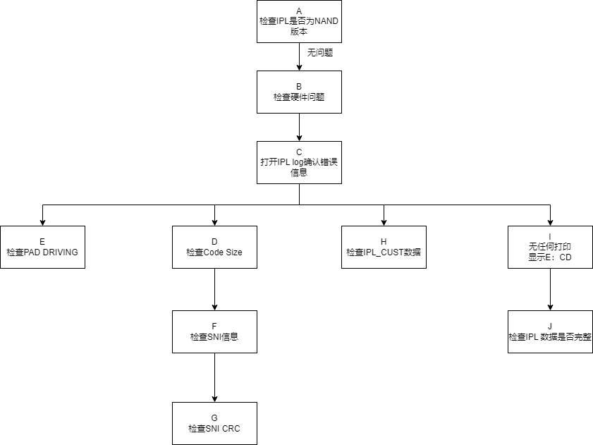
| Step | Method | Exit Condition | Next Step | Materials Required for SWRD | Related FAQ |
|---|---|---|---|---|---|
| A | Check IPL build configuration | Exit Condition 1: IPL is built with NAND option Exit Condition 2: IPL build option is incorrect |
Exit Condition 1: >B Exit Condition 2: >Rebuild IPL |
||
| B | 1. Check for cold solder joints on SoC chip 2. Check for cold solder joints on Flash chip 3. Verify Flash voltage matches datasheet specifications 4. Check if waveforms are synchronized between SoC and Flash pins |
Exit Condition 1: Hardware confirmed OK Exit Condition 2: Hardware issue exists |
Exit Condition 1: >C Exit Condition 2: >Request CAE rework based on specific hardware issue |
1. Branch information 2. Build config 3. Branch information 4. Reproduction steps on reference board 5. Flash datasheet |
|
| C | Flash IPL with log enabled and confirm error message type reported by IPL | Exit Condition 1: SNI initialization succeeds, load IPL_CUST Header directly halts or behavior varies each boot Exit Condition 2: Reports "no sni" Exit Condition 3: Log prints "load IPL_CUST check sum fail" Exit Condition 4: Prints "E:CD" |
Exit Condition 1: >E Exit Condition 2: >D Exit Condition 3: >H Exit Condition 4: >I |
||
| D | Check if IPL code size exceeds maximum specification | Exit Condition 1: IPL size does not exceed maximum limit Exit Condition 2: IPL size exceeds maximum limit |
Exit Condition 1: >F Exit Condition 2: >Contact PM to arrange code size reduction |
||
| E | Request CAE to capture waveforms with oscilloscope and adjust pad driving based on waveform analysis | Exit Condition 1: Boot succeeds after adjusting pad driving Exit Condition 2: Waveform still marginal after adjusting pad driving |
Exit Condition 1: >End of process Exit Condition 2: >Request CAE rework, add capacitor at Flash pins |
||
| F | Check if SNI information includes current Flash | Exit Condition 1: Includes current Flash Exit Condition 2: Does not include current Flash |
Exit Condition 1: >G Exit Condition 2: >Add Flash SNI information according to SNI manual |
||
| G | Check if SNI information in generated CIS file has CRC calculated, CIS file can be provided to RD for confirmation | Exit Condition 1: CRC data is empty Exit Condition 2: CRC data is calculated |
Exit Condition 1: >Check if packaging script uses snigenerator to calculate SNI CRC Exit Condition 2: >End of process, contact RD |
1. Branch information 2. Build config 3. Branch information 4. Reproduction steps on reference board 5. Flash datasheet |
|
| H | Check IPL_CUST checksum in CIS file | Exit Condition 1: Checksum error |
Exit Condition 1: ==>Rebuild and repackage |
||
| I | Check log output | Exit Condition 1: Log prints "E:CD" |
Exit Condition 1: ==>J |
||
| J | Use ISP tool to connect Flash, then dump IPL partition data and compare with original bin file | Exit Condition 1: Data matches Exit Condition 2: Data does not match |
Exit Condition 1: >Contact RD Exit Condition 2: >Reflash IPL |
1. Branch information 2. Build config 3. Branch information 4. Reproduction steps on reference board 5. Flash datasheet |
Issue 4. SPI NAND ISP Tool Connection Failure
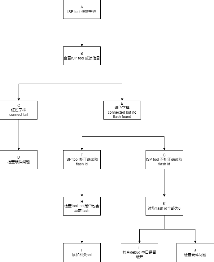
| Step | Method | Exit Condition | Next Step | Materials Required for SWRD | Related FAQ |
|---|---|---|---|---|---|
| A | N/A | Exit Condition 1: ISP tool fails to connect Flash |
Exit Condition 1: ==>B |
||
| B | Check feedback message from ISP tool during connection | Exit Condition 1: Red text message |
N/A | ||
| C | N/A | Exit Condition 1: Connection feedback shows red text |
Exit Condition 1: ==>D |
||
| D | Request CAE assistance: 1. Check for cold solder joints on SoC chip 2. Check for cold solder joints on Flash chip 3. Verify Flash voltage matches datasheet specifications 4. Check if waveforms are synchronized between SoC and Flash pins 5. Check if jumper settings are correct |
Exit Condition 1: Connection still fails Exit Condition 2: Connection succeeds |
Exit Condition 1: >Contact RD for troubleshooting Exit Condition 2: >End of process |
1. Provide remote environment with LA available, RD will guide waveform capture | |
| E | N/A | Exit Condition 1: ISP tool white window correctly reports Flash ID Exit Condition 2: ISP tool white window reports incorrect ID |
Exit Condition 1: >F Exit Condition 2: >G |
||
| F | N/A | Exit Condition 1: ISP tool white window correctly reports Flash ID |
Exit Condition 1: ==>H |
||
| G | N/A | Exit Condition 1: ISP tool white window reports ID as 0x00 |
Exit Condition 1: ==>L & J (check simultaneously) |
||
| H | Use SNI editor (available from RD) to open SNI file in tool directory, check if corresponding Flash model exists and verify ID information matches | Exit Condition 1: No Flash related information Exit Condition 2: Flash related information exists |
Exit Condition 1: >I Exit Condition 2: >End of process, contact RD |
||
| I | Add SNI according to SNI manual | N/A | N/A | ||
| J | Same method as D | N/A | N/A | ||
| L | Close software used for viewing UART log | N/A | N/A |