SGS Audio Debug SOP Manual
REVISION HISTORY
| Revision No. | Description |
Date |
|---|---|---|
| 1.0 | 16/12/2024 | |
| 1.1 | 06/10/2025 |
Issue 1. Speaker Playback Silence
| Process | Method | Exit Condition |
Next Step |
Information Required by SWRD |
Relevant FAQ |
|---|---|---|---|---|---|
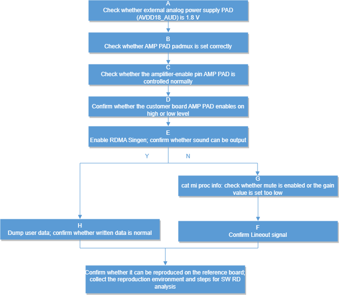
| A | During playback, use a multimeter to confirm whether AUDIO's AUDD18_AUD is 1.8V | Exit Condition 1: 1. During playback, AUDD18_AUD voltage differs significantly from 1.8V Exit Condition 2: 2. During playback, AUDD18_AUD is stable at approximately 1.8V |
Exit Condition 1: >External power supply issue exists, seek CAE assistance. Exit Condition 2: >External power supply is normal ==>B |
||
| B | Confirm whether the AMP pad padmux configuration matches the board (check if the amp pad on the EVB schematic matches the amp pad in padmux.dtis) | Exit Condition 1: 1.Pad is correct Exit Condition 2: 2.Pad does not match the board |
Exit Condition 1: >C Exit Condition 2: >Please modify the amp pad in padmux.dtsi accordingly |
||
| C | During playback, use a voltmeter to confirm whether the AMP pad can be pulled high and low normally |
Exit Condition 1: 1.Can be pulled high and low normally Exit Condition 2: 2. Cannot be pulled high and low |
Exit Condition 1: >D Exit Condition 2: Trace routing abnormal>Please seek CAE assistance for troubleshooting |
||
| D | Confirm whether the customer board AMP PAD is enabled by pull-high or pull-low | Exit Condition 1: 1.Pull-high enable Exit Condition 2: 2.Pull-low enable |
Exit Condition 1: >E Exit Condition 2: > Modify the parameter in the corresponding board's dtsi sound node node:amp-pad: change 1 to 0 indicating low-level enable |
||
| E | During playback, enable RDMA Singen to confirm whether sound can be output echo singen [SinGen Index][Enable] > /proc/mi_modules/mi_ao/mi_aox SinGen 0: Device0. SinGen 1: Device1. SinGen 2: Device2. SinGen 3: Device3. Example: echo singen 0 1 > /proc/mi_modules/mi_ai/mi_ai0, to enable singen for Device0 |
Exit Condition 1: 1.Sound can be output Exit Condition 2: 2. Sound cannot be output |
Exit Condition 1: >H Exit Condition 2: >F |
||
| F | Cat mi proc info to confirm whether it is muted or if the gain value is set too small | Exit Condition 1: 1.Description issue exists Exit Condition 2: 2. No description issue |
Exit Condition 1: ==> Confirm settings with customer Exit Condition 2: ==> G |
||
| G | During playback, use an oscilloscope to capture the lineout output while RDMA Singen is enabled | Exit Condition 1: 1.lineout has signal Exit Condition 2: 2.lineout has no signal |
Exit Condition 1: >Seek CAE assistance to confirm if it is an amplifier issue Exit Condition 2: >After confirming that the oscilloscope captured no signal from the chip output, seek SW RD assistance |
Whether the issue can be reproduced on the reference board, environment setup method | |
| H | Dump user data to confirm whether the written data is normal | Exit Condition 1: Dump data is normal Exit Condition 2: Dump data is abnormal |
Exit Condition 1: > Seek SW RD assistance Exit Condition 2: > Investigate customer app issues |
Confirm whether the issue can be reproduced on the reference board, the environment to reproduce the issue, and the method to reproduce the issue | |
| --- |
Issue 2. AMIC Recording No Data
| Process | Method | Exit Condition |
Next Step |
Information Required by SWRD |
Relevant FAQ |
|---|---|---|---|---|---|
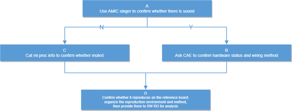
| A | Enable Amic Sinegen during recording to confirm whether a sine wave can be recorded (refer to MI_AI documentation for Singen enable method) | Exit Condition 1: 1.No sound recorded Exit Condition 2: 2. Sound can be recorded |
Exit Condition 1: Most likely a software issue, perform software troubleshooting==>C Exit Condition 2:Most likely a hardware issue, perform hardware troubleshooting==>B |
||
| B | Seek CAE to confirm hardware issues, including Audio 1.8V power supply, AMIC bias, and AMIC wiring location, as well as other hardware-related issues |
Exit Condition 1: 1.Hardware confirmed no issues Exit Condition 2: 2.Hardware issue found |
Exit Condition 1: ==>D Exit Condition 2: CAE assistance |
||
| C | Cat mi proc info to confirm whether the AI interface is muted | Exit Condition 1: 1.No mute Exit Condition 2: 2. Mute exists |
Exit Condition 1: ==> Seek SW RD for analysis Exit Condition 2: Investigate customer APP settings |
Confirm whether the issue can be reproduced on the reference board, the environment to reproduce the issue, and the method to reproduce the issue |
Issue 3. I2S Codec Adaptation Issues
| Process | Method | Exit Condition |
Next Step |
Information Required by SWRD |
Relevant FAQ |
|---|---|---|---|---|---|
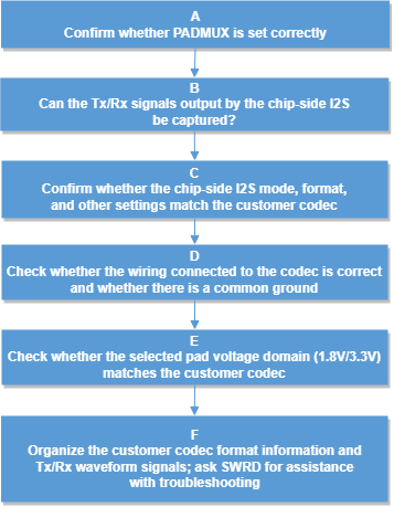
| A | Confirm whether the AUDIO I2S PAD padmux configuration matches the development board, and whether the pad conflicts with other modes Method: cd vim arch/arm/boot/dts/xxx_xxxx-padmux.dtsi Search for whether I2S PAD has been switched to MDRV_PUSE_I2S0_XX_XXX mode, and use IO_Check Tool to check if the mode setting is successful (./io_check_xxx PinID) |
Exit Condition 1: 1.padmux is not correctly configured or conflicts with other modes Exit Condition 2: 2.I2S PAD configuration is normal |
Exit Condition 1: >Assist customer in modifying padmux settings Exit Condition 2: > B |
||
| B | Run mi_demo prog_audio_audio corresponding I2S case and use an oscilloscope to capture Tx or Rx signals | Exit Condition 1: Normal tx rx clk data signals can be captured Exit Condition 2: No signal can be captured, or signal is abnormal |
Exit Condition 1: >C Exit Condition 2: > Seek CAE to confirm pad trace routing issues and interference issues |
||
| C | Confirm whether the chip-side I2S mode format and other formats match the customer codec, refer to MI API documentation | Exit Condition 1: Format is normal Exit Condition 2: Format is abnormal |
Exit Condition 1: >D Exit Condition 2: >Assist customer in modifying I2S format |
||
| D | Confirm whether the wiring sequence connected to the codec is correct, and whether there is common ground In 6-wire mode: TX_BCK<>RX_BCK TX_WCK<>RX_WCK TX_SDO<>RX_SDI PS:codec's LRCK is WCK In 4-wire mode: RX_BCK<>RX_BCK RX_WCK<>RX_WCK RX_SDI<>TX_SD0 TX_SD0<==>RX_SDI |
Exit Condition 1: Wiring sequence is normal, common ground exists Exit Condition 2: Wiring sequence is abnormal, no common ground |
Exit Condition 1: ==> E Exit Condition 2: ==>Assist customer in confirming wiring sequence issues |
||
| E | Confirm whether the selected pad voltage domain 1.8V/3.3V matches the customer codec | Exit Condition 1: Voltage matches Exit Condition 2: Voltage does not match |
Exit Condition 1: ==> Compile customer codec information, Tx Rx waveform signals, seek SW RD assistance for troubleshooting Exit Condition 2:Seek CAE to confirm the method to switch to the corresponding pad voltage domain |
||
| --- |
Issue 4. DMIC Operation Abnormality Issues
| Process | Method | Exit Condition |
Next Step |
Information Required by SWRD |
Relevant FAQ |
|---|---|---|---|---|---|
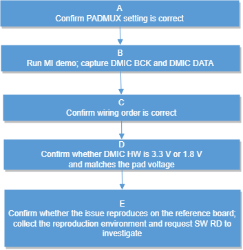
| A | Confirm whether the AUDIO DMIC PAD padmux configuration matches the development board, and whether the pad conflicts with other modes Method: cd vim arch/arm/boot/dts/xxx_xxxx-padmux.dtsi Search for whether DMIC PAD has been switched to MDRV_PUSE_DMIC0_XX mode, and use IO_Check Tool to check if the mode setting is successful (./io_check_xxx PinID) |
Exit Condition 1: >padmux is not correctly configured or conflicts with other modes Exit Condition 2: >DMIC PAD configuration is normal |
Exit Condition 1: >Assist customer in confirming padmux issues Exit Condition 2: > B |
||
| B | Run prog_audio_audio dmic demo and capture DMIC BCK and DMIC data |
Exit Condition 1: 1.BCK 2.4M and Data has data Exit Condition 2: No BCK, no Data Exit Condition 3: Has BCK, no Data |
Exit Condition 1: ==>C Exit Condition 2: Seek CAE to confirm whether trace routing issues exist Exit Condition 3: Seek CAE to confirm whether DMIC is damaged |
||
| C | Confirm whether the wiring sequence is correct DMIC wiring sequence is relatively simple, mainly CLK, data, power, and ground |
Exit Condition 1: Wiring sequence is correct Exit Condition 2: Wiring sequence is incorrect |
Exit Condition 1: ==>D Exit Condition 2: Assist customer in clarifying wiring sequence |
||
| D | Confirm whether DMIC hardware is 3.3V or 1.8V, and confirm whether the currently selected pad is 3.3V or 1.8V, voltages need to match | Exit Condition 1: 1.Voltages match Exit Condition 2: 2. Voltages do not match |
Exit Condition 1: > Compile the environment to reproduce the issue, confirm whether customer dmic spec can reproduce the issue on the reference board, seek SW RD assistance Exit Condition 2: > Seek CAE to confirm the voltage domain adjustment method |
Customer DMIC spec Reference board reproduction environment |
Issue 5. AI Interface Known Issues FAQ
5.1 AI Unable to Retrieve Data Issue
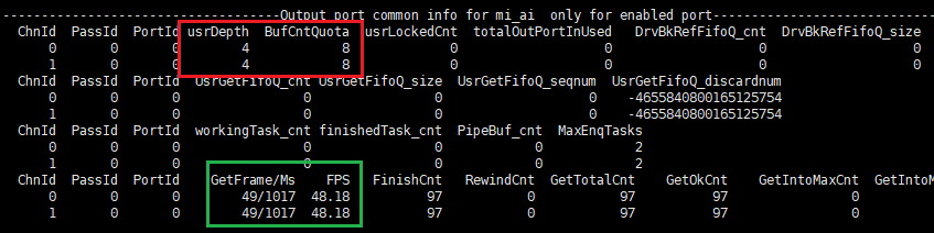
Based on the specific scenario, capture the device's proc information to view the current buffer configuration and usage. cat /proc/mi_modules/mi_ai/mi_aix
Confirm the output buffer configuration. usrDepth and BufCntQuota represent the number of buffers available to the application and the total number of buffers, respectively. Check whether usrDepth and BufCntQuota are set to 0.
 Confirm the buffer retrieval status by the application. usrLockedCnt indicates the number of buffers held by the application without release. If usrLockedCnt equals usrDepth, it indicates that the application has captured all available output buffers.
5.2. Buffer Interval Instability (Buffer Loss)
Based on the specific scenario, capture the device's proc information to view the current buffer configuration and usage. cat /proc/mi_modules/mi_ai/mi_aix
- Confirm the output buffer configuration. usrDepth and BufCntQuota represent the number of buffers available to the application and the total number of buffers, respectively. Check whether usrDepth and BufCntQuota are too small, causing buffer retrieval by the application to affect normal AI thread operation.
- If buffers are sufficient but GetFrame/Ms and FPS are significantly lower than expected, compile the information and contact the audio owner.
5.3. Sound Clipping with Normal Sampling Values
This issue is commonly observed in AMIC and DMIC interfaces. Both interfaces have interface gain and DPGA gain in their signal paths. A common scenario is that the interface gain is set too high causing clipping, and then attenuation is applied through DPGA gain, causing the sampling values to return to the normal range.
5.4. AMIC Pop Noise Issue
Root Cause: The ADC reference capacitor needs to charge to 0.9V. Recording with the ADC before the capacitor is fully charged results in noise, which is pop noise.
Solution:
-
For chips after ifackel, a fast charging design for the capacitor has been added. The default code includes a 50ms delay, so this issue does not occur.
-
For chips before ifackel, it is necessary to enable keep adc on in dtsi to resolve this issue by increasing power consumption.
-
In fast boot scenarios where time is critical and delay is not desired, enable SGS_BACH SGS_BACH_FAST_BOOT in IPL to resolve the issue by enabling ADC reference capacitor charging during IPL.
5.5. DMIC Pop Noise Issue
There are two root causes:
-
DMIC hardware cannot provide valid data immediately after receiving BCK. Typically, it takes approximately 10ms to output valid data. This abnormal data will be received by the IC and accumulated to an abnormal value, resulting in pop noise.
-
Many DMIC hardware devices have DC bias. The internal HPF module of the IC can pull the DC bias back to the median value, but this process takes time. The presence of bias also causes pop noise.
Solution:
- Add dmic-delay = <80> field to the dtsi sound node; The parameter 80 represents the delay time. By delaying for 80ms, the pop noise issue is avoided.
Issue 6. AO Interface Known Issues FAQ
6.1. DAC Pop Noise Issue
There are two root causes:
- Voltage change at the moment of DAC activation
- The DAC reference capacitor requires time to charge. Activating the DAC before it is fully charged also results in sound abnormality.
Solution:
-
For chips after ifackel, a fast charging design for the capacitor has been added. By delaying for 50ms to wait for capacitor charging completion, the voltage change at DAC activation is also avoided. The amplifier pad is then activated, and the DAC pop noise issue is resolved through amp mute.
-
For chips before ifackel, it is necessary to enable keep dac on in dtsi to resolve this issue by increasing power consumption.
Issue 7. Noise Issue When Speaker Amplifier Gain is Adjusted to 9x
Issue Background: For Pcupid customers with 1.8V IO, the amplifier gain is adjusted to 9x to meet expected output power. During program execution, noise can be heard from the speaker. At this time, audio is not enabled. Only the amplifier is enabled.
Root Cause: When CPU loading is high, internal current noise from the chip couples from GND to the amplifier. When the amplifier is enabled, noise can be heard.
Solution: This issue can only be resolved by using a differential amplifier to address GND noise. Since both input signals of the differential amplifier carry noise, the noise can be eliminated through differential processing. Additionally, request CAE to change the Audio AUD_VRM pad grounding to a relatively clean GND, similar to that of the amplifier.