GMAC User Guide
REVISION HISTORY
| Revision No. | Description |
Date |
|---|---|---|
| 1.0 | 10/16/2024 | |
| 1.1 | 1/14/2025 | |
| 1.2 | 5/15/2025 | |
| 1.3 | 5/22/2026 |
1. INTRODUCTION
Gigabit Media Access Control (GMAC) is mainly responsible for controlling and managing the physical layer and data link layer in Ethernet data communications.
From a hardware perspective:
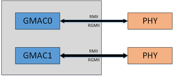
The hardware architecture is shown in the figure. There are two GMAC controllers: GMAC0 and GMAC1
GMAC0: supports RGMII external Gphy (1000M), RMII external Ephy (100M)
GMAC1: supports RGMII external Gphy (1000M), RMII external Ephy (100M)
From a software perspective:
-
UBOOT
GMAC0: Use RGMII by default, can be switched to RMII
GMAC1: Use RGMII by default, can be switched to RMII
In UBOOT, only one GMAC can be selected at a time, which can be switched through ENV configuration
-
KERNEL
GMAC0: Use RGMII by default, can be switched to RMII
GMAC1: Use RGMII by default, can be switched to RMII
In KERNEL, two GMACs can be used at the same time
2. Keyword Description
-
GMAC
Gigabit Media Access Control is abbreviated as GMAC.
-
Gphy
Gigabit Ethernet Physical Layer is abbreviated as Gphy.
-
Ephy
Ethernet Physical Layer is abbreviated as Ephy.
-
MII
MII (Media Independent Interface) is a media independent interface. MII interface is a standard interface for connecting MAC and PHY. MII interface provides interconnection support between MAC and PHY.
-
RMII
RMII (Reduced Media Independent Interface) is a simplified media independent interface. It is one of the standard Ethernet interfaces and has fewer I/O transmission pins than MII.
-
RGMII
RGMII (Reduced Gigabit Media Independent Interface) is a simplified Gigabit Media Independent Interface. It is one of the standard Ethernet interfaces. It is a simplified version of GMII, reducing the number of interface signal lines from 24 to 14.
-
RX
Receiver or Reception.
-
TX
Transmitter or Transmission.
3. GMAC Function Description
3.1. FLOW CONTROL
Data loss is prone to occur during transmission. For example, when two computers transmit data through serial ports, or when a desktop computer communicates with a single-chip microcomputer, the data buffer at the receiving end may be full due to the different processing speeds of the computers at both ends, while the sending end continues to send data, resulting in data loss.
Flow control (FLOW CONTROL) is designed to solve this problem of data loss. In full-duplex applications, flow control is performed through PAUSE frames.
When the receiving end cannot process the data, it sends a "no more receiving" signal (PAUSE frame), and the sending end stops sending until it receives a "can continue sending" signal. Therefore, flow control can control the process of data transmission and prevent data loss. The PAUSE frame is a packet that implements flow control at the link layer and is automatically processed by the link.
For example, when a 100M network card sends data frames to a 10M network card through a switch, the 10M network card may suffer from buffer overflow due to rate limitations, resulting in frame loss. When the 10M network card finds that its buffer is about to overflow, it can send a PAUSE frame, asking the device that receives the PAUSE frame to pause for a while before sending packets.
3.1.1. PAUSE frame format
The format of the PAUSE frame is shown in the figure below:

If it is PAUSE_ON pkt, then time_unit is not 0. The current default is 0xFFFF.
If it is PAUSE_OFF pkt, then time_unit is 0. When PAUSE_OFF pkt is received, it means that the flow control has been turned off and the tx pkt can be normally transmitted, that is, it has a wake-up function.
time-unit is the pause transmission time parameter, the unit is the time to transmit 512 bits at the current rate, that is, slot time; some common values can be found in the table below.
| value | 10M pause time | 100M pause time | 1000M pause time |
|---|---|---|---|
| 20 | 1ms | 100us | 10us |
| 200 | 10ms | 1ms | 100us |
| 2000 | 100ms | 10ms | 1ms |
| 20000 | 1s | 100ms | 10ms |
| 60000 | 3s | 300ms | 30ms |
| 65535 | 3.27s | 327ms | 32.7ms |
3.1.2. How to enable and disable PAUSE
-
You can configure the disable-txfc property switch FLOW CONTROL TX in the dtsi file, which is set to off by default.
gmac0 { …… disable-txfc = /bits/ 8 <1>; //The last <1> means turning off FLOW CONTROL TX, and setting it to <0> turns on FLOW CONTROL TX. …… }; -
You can switch to software flow_ctrl by configuring SGS_SNPS_SW_TX_FLOW_CTL in menuconfig. It is not enabled by default, and uses hw flow control.
Device Drivers ---> Sgs SoC platform drivers ---> SGS GMAC ---> <*> SGS GMAC [ ] SGS_SNPS_SW_TX_FLOW_CTL -
Can be controlled by ethtool, tx refers to the transmission direction flow control, indicating whether eth0 can pause the transmission when receiving a PAUSE frame while transmitting traffic; rx refers to the receiving direction flow control, indicating whether eth0 can send a PAUSE frame to the other end when receiving traffic.
./ethtool -a eth0                 // Display the current flow control status
./ethtool -A eth0 rx on tx on     // Turn on the flow control of tx rx
./ethtool -A eth0 rx off tx off   // Turn off the flow control of tx rx
3.2. NETWORK STORM
Broadcast storm: refers to the situation where the network is flooded with broadcast data and cannot be processed, occupying a large amount of network bandwidth, causing normal business to fail to run, or even completely paralyzed.
To address this issue, you can enable the network storm protection function, and the network card can limit the sending and receiving bandwidth of unicast, multicast, and broadcast. For broadcast storm scenarios, you can choose to use broadcast traffic limit to solve the problem.
3.2.1. Packet filtering rate
-
The theoretical limit rate of NETWORK STORM = RX_CLK / filter value (consume). You can get the desired limit rate by modifying the filter value.
-
At different rates, the value of RX_CLK is different
SPEED RX_CLK 1000 125MHz 100 25MHz 10 2.5MHz
Therefore, when consume is 2500, the rate limit at 100M is 25MHz / 2500 = 10000 Packets/s.
In addition, max means that (max / consume) packets can be received at full speed at the beginning. When so many packets are received, the subsequent packet receiving rate is as described above (RX_CLK / consume).
3.2.2. Filter value configuration reference
Currently, five configuration gears are provided for reference. The rate limits in different situations are as follows:
| level | consume | 1000M limit rate Packets/s | 100M limit rate Packets/s | 10M limit rate Packets/s |
|---|---|---|---|---|
| 1 | 2500 | 50000 | 10000 | 1000 |
| 2 | 5000 | 25000 | 5000 | 500 |
| 3 | 10000 | 12500 | 2500 | 250 |
| 4 | 20000 | 6250 | 1250 | 125 |
| 5 | 40000 | 3125 | 625 | 62.5 |
The actual filtering effect will have a slight error. You can adjust the consumption according to the actual usage performance.
3.2.3. Use the register to enable network storm protection
Currently, network storm protection is not enabled by default, and you need to enable it by configuring the register.
3.2.3.1. gmac0
-
unicast protection
/customer/riu_w 1510 10 9C40 //Maximum value max lower 16 bits /customer/riu_w 1510 11 0000 //Maximum value max upper 16 bits /customer/riu_w 1510 12 9C40 //Filter value consume lower 16 bits [15,0] /customer/riu_w 1510 13 0000 //Filter value consume upper 12 bits [27,16] /customer/riu_w 1510 28 0001 //bit 0 enable -
multicast protection
/customer/riu_w 1510 18 9C40 //maximum value max lower 16 bits /customer/riu_w 1510 19 0000 //maximum value max upper 16 bits /customer/riu_w 1510 1a 9C40 //filter value consume lower 16 bits [15,0] /customer/riu_w 1510 1b 0000 //filter value consume upper 12 bits [27,16] /customer/riu_w 1510 28 0002 //bit 1 enable -
broadcast protection
/customer/riu_w 1510 20 9C40   //maximum value max lower 16 bits
/customer/riu_w 1510 21 0000   //maximum value max High 16 bits
/customer/riu_w 1510 22 9C40   //Filter value consume low 16 bits [15,0]
/customer/riu_w 1510 23 0000   //Filter value consume high 12 bits [27,16]
/customer/riu_w 1510 28 0004   //bit 2 enable
3.2.3.2. gmac1
-
unicast protection
/customer/riu_w 1513 10 9C40 //Maximum value max lower 16 bits /customer/riu_w 1513 11 0000 //Maximum value max upper 16 bits /customer/riu_w 1513 12 9C40 //Filter value consume lower 16 bits [15,0] /customer/riu_w 1513 13 0000 //Filter value consume upper 12 bits [27,16] /customer/riu_w 1513 28 0001 //bit 0 enable -
multicast protection
/customer/riu_w 1513 18 9C40 //maximum value max lower 16 bits /customer/riu_w 1513 19 0000 //maximum value max upper 16 bits /customer/riu_w 1513 1a 9C40 //filter value consume lower 16 bits [15,0] /customer/riu_w 1513 1b 0000 //filter value consume upper 12 bits [27,16] /customer/riu_w 1513 28 0002 //bit 1 enable -
broadcast protection
/customer/riu_w 1513 20 9C40   //maximum value max lower 16 bits
/customer/riu_w 1513 21 0000   //maximum value max High 16 bits
/customer/riu_w 1513 22 9C40   //Filter value consume low 16 bits [15,0]
/customer/riu_w 1513 23 0000   //Filter value consume high 12 bits [27,16]
/customer/riu_w 1513 28 0004   //bit 2 enable
3.3. IPV6
The kernel provides ipv6 function. If you need to use the IPV6 function, you need to enable the corresponding CONFIG, (enabled by default).
- Enable ipv6 support in the kernel
-> Networking support (NET [=y])
    -> Networking options
        -> TCP/IP networking (INET [=y])
            <*>   The IPv6 protocol
4. Introduction to hardware connection
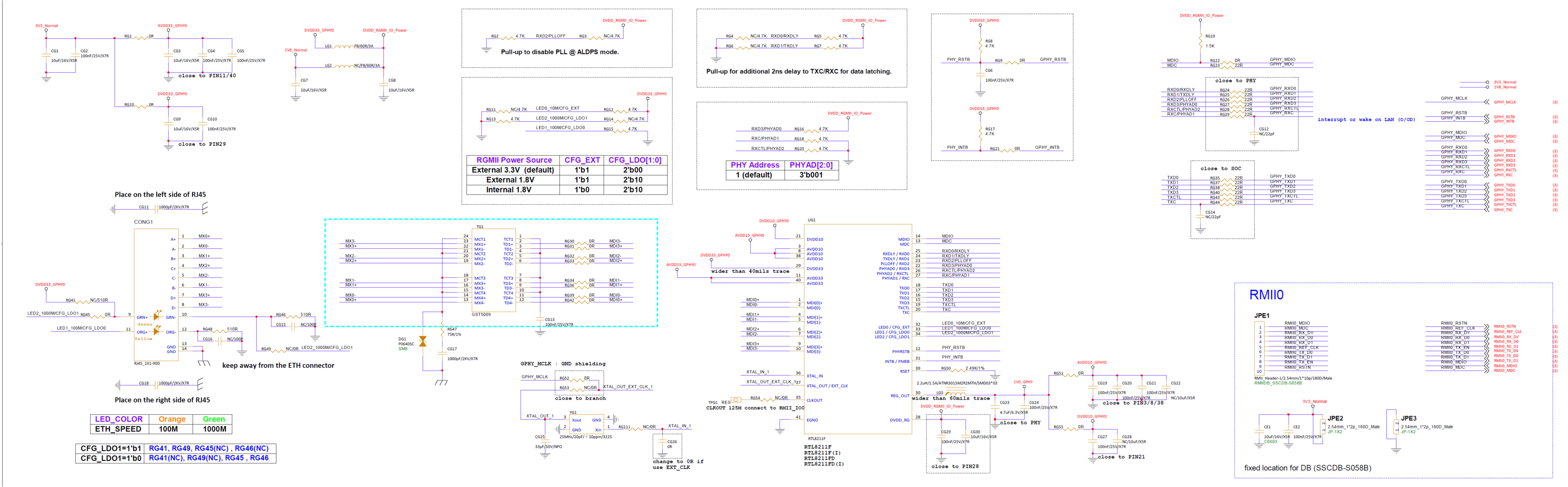
Take mhera-ssm004a-s01a gmac0 as an example, RGMII/RMII wiring is as follows:
5. Uboot Usage Introduction
5.1. uboot config configuration instructions
- Enable or disable GMAC config configuration path.
Sgs drivers ---> (SGS_DRIVERS [=y])
    Sgs GMAC --->
        [*] Sgs GMAC
5.2. Dts Configuration & Padmux Configuration
5.2.1 Dts Configuration
Take mhera as an example. The DTS of GMAC0 needs to be configured in the corresponding chipname.dtsi according to actual use:
    gmac0: gmac0 {
        compatible = "sgs,gmac","snps,dwmac-5.10a";
        reg = <0x1F34A000 0x1300>;
        gmac-bank = <0x1A50>, <0x1A51>, <0x1A52>, <0x1A53>, <0x1A54>, <0x1A55>, <0x1A56>, <0x1A57>;
        gmac-id = <0>;
        clock-names = "gmac-clk", "mclk";
        mclk = /bits/ 8 <25>; // Mclk frequency : 0, 25M, 50M
        mclk-refmode = /bits/ 8 <1>; //mclk padmux : 1 or 2
        reset-io = /bits/ 8 <PAD_RGMII0_RSTN>;
        phy-mode = "rgmii";
        max-speed = <1000>;
        status = "okay";
    };
DTS configuration instructions:
| Property | Description | Setting value |
|---|---|---|
| compatible | Property information, driver version information | |
| reg | Physical address of register mapping | |
| gmac-bank | Bank address corresponding to register | |
| gmac-id | gmac ID | |
| clocks-name | Clock name used by gmac | |
| mclk | Configure whether to output mclk (if you want to save the external crystal oscillator of PHY, you can let the main control chip generate clock for PHY) | 0: No output; 25: Output 25MHz |
| mclk-refmode | Specify the PAD to be output, 1: RGMIIX_MCLK, 2: RGMIIX_RSTN. | <1>/<2> |
| reset-io | Designate the io pin for phy to reset | <PAD_RGMII0_RSTN>/<PAD_RGMII0_MCLK> |
| phy-mode | The phy interface provides three interface options (need to be combined with the specifications described in INTRODUCTION) | "rmii"/"rgmii" |
| max-speed | Limit the maximum rate under auto-negotiation, three gear options | <10>/<100>/<1000> |
| status | Driver switch | "ok"/"disabled" |
- mclk-refmode currently only supports RGMIIX_MCLK output.
5.2.2 Padmux Configuration
Add the following code to the corresponding padmux.dtsi according to the selected pin:
-
RGMII PADMUX configuration of GMAC0:
// GMAC0 RGMII <PAD_RGMII0_RSTN PINMUX_FOR_GPIO_MODE MDRV_PUSE_ETH0_PHY_RESET>, <PAD_RGMII0_MCLK PINMUX_FOR_RGMII0_MCLK_MODE_1 MDRV_PUSE_ETH0_MCLK>, <PAD_RGMII0_RXCLK PINMUX_FOR_RGMII0_MODE_1 MDRV_PUSE_ETH0_RX_CLK>, <PAD_RGMII0_RXCTL PINMUX_FOR_RGMII0_MODE_1 MDRV_PUSE_ETH0_RX_CTL>, <PAD_RGMII0_RXD0 PINMUX_FOR_RGMII0_MODE_1 MDRV_PUSE_ETH0_RXD0>, <PAD_RGMII0_RXD1 PINMUX_FOR_RGMII0_MODE_1 MDRV_PUSE_ETH0_RXD1>, <PAD_RGMII0_RXD2 PINMUX_FOR_RGMII0_MODE_1 MDRV_PUSE_ETH0_RXD2>, <PAD_RGMII0_RXD3 PINMUX_FOR_RGMII0_MODE_1 MDRV_PUSE_ETH0_RXD3>, <PAD_RGMII0_TXCLK PINMUX_FOR_RGMII0_MODE_1 MDRV_PUSE_ETH0_TX_CLK>, <PAD_RGMII0_TXCTL PINMUX_FOR_RGMII0_MODE_1 MDRV_PUSE_ETH0_TX_CTL>, <PAD_RGMII0_TXD0 PINMUX_FOR_RGMII0_MODE_1 MDRV_PUSE_ETH0_TXD0>, <PAD_RGMII0_TXD1 PINMUX_FOR_RGMII0_MODE_1 MDRV_PUSE_ETH0_TXD1>, <PAD_RGMII0_TXD2 PINMUX_FOR_RGMII0_MODE_1 MDRV_PUSE_ETH0_TXD2>, <PAD_RGMII0_TXD3 PINMUX_FOR_RGMII0_MODE_1 MDRV_PUSE_ETH0_TXD3>, <PAD_RGMII0_MDIO PINMUX_FOR_RGMII0_MODE_1 MDRV_PUSE_ETH0_MDIO>, <PAD_RGMII0_MDC PINMUX_FOR_RGMII0_MODE_1 MDRV_PUSE_ETH0_MDC>, -
RMII PADMUX configuration for GMAC0:
// GMAC0 RMII <PAD_RGMII0_RSTN PINMUX_FOR_GPIO_MODE MDRV_PUSE_ETH0_PHY_RESET>, <PAD_RGMII0_RXCLK PINMUX_FOR_RMII0_MODE_1 MDRV_PUSE_ETH0_RX_CLK>, <PAD_RGMII0_RXCTL PINMUX_FOR_RMII0_MODE_1 MDRV_PUSE_ETH0_RX_CTL>, <PAD_RGMII0_RXD0 PINMUX_FOR_RMII0_MODE_1 MDRV_PUSE_ETH0_RXD0>, <PAD_RGMII0_RXD1 PINMUX_FOR_RMII0_MODE_1 MDRV_PUSE_ETH0_RXD1>, <PAD_RGMII0_TXCTL PINMUX_FOR_RMII0_MODE_1 MDRV_PUSE_ETH0_TX_CTL>, <PAD_RGMII0_TXD0 PINMUX_FOR_RMII0_MODE_1 MDRV_PUSE_ETH0_TXD0>, <PAD_RGMII0_TXD1 PINMUX_FOR_RMII0_MODE_1 MDRV_PUSE_ETH0_TXD1>, <PAD_RGMII0_MDIO PINMUX_FOR_RMII0_MODE_1 MDRV_PUSE_ETH0_MDIO>, <PAD_RGMII0_MDC PINMUX_FOR_RMII0_MODE_1 MDRV_PUSE_ETH0_MDC>, -
RGMII PADMUX configuration for GMAC1:
// GMAC1 RGMII <PAD_RGMII1_RSTN PINMUX_FOR_GPIO_MODE MDRV_PUSE_ETH1_PHY_RESET>, <PAD_RGMII1_MCLK PINMUX_FOR_RGMII1_MCLK_MODE_1 MDRV_PUSE_ETH1_MCLK>, <PAD_RGMII1_RXCLK PINMUX_FOR_RGMII1_MODE_1 MDRV_PUSE_ETH1_RX_CLK>, <PAD_RGMII1_RXCTL PINMUX_FOR_RGMII1_MODE_1 MDRV_PUSE_ETH1_RX_CTL>, <PAD_RGMII1_RXD0 PINMUX_FOR_RGMII1_MODE_1 MDRV_PUSE_ETH1_RXD0>, <PAD_RGMII1_RXD1 PINMUX_FOR_RGMII1_MODE_1 MDRV_PUSE_ETH1_RXD1>, <PAD_RGMII1_RXD2 PINMUX_FOR_RGMII1_MODE_1 MDRV_PUSE_ETH1_RXD2>, <PAD_RGMII1_RXD3 PINMUX_FOR_RGMII1_MODE_1 MDRV_PUSE_ETH1_RXD3>, <PAD_RGMII1_TXCLK PINMUX_FOR_RGMII1_MODE_1 MDRV_PUSE_ETH1_TX_CLK>, <PAD_RGMII1_TXCTL PINMUX_FOR_RGMII1_MODE_1 MDRV_PUSE_ETH1_TX_CTL>, <PAD_RGMII1_TXD0 PINMUX_FOR_RGMII1_MODE_1 MDRV_PUSE_ETH1_TXD0>, <PAD_RGMII1_TXD1 PINMUX_FOR_RGMII1_MODE_1 MDRV_PUSE_ETH1_TXD1>, <PAD_RGMII1_TXD2 PINMUX_FOR_RGMII1_MODE_1 MDRV_PUSE_ETH1_TXD2>, <PAD_RGMII1_TXD3 PINMUX_FOR_RGMII1_MODE_1 MDRV_PUSE_ETH1_TXD3>, <PAD_RGMII1_MDIO PINMUX_FOR_RGMII1_MODE_1 MDRV_PUSE_ETH1_MDIO>, <PAD_RGMII1_MDC PINMUX_FOR_RGMII1_MODE_1 MDRV_PUSE_ETH1_MDC>, -
RMII PADMUX configuration of GMAC1:
// GMAC1 RMII
<PAD_RGMII1_RSTN         PINMUX_FOR_GPIO_MODE            MDRV_PUSE_ETH1_PHY_RESET>,
<PAD_RGMII1_RXCLK        PINMUX_FOR_RMII1_MODE_1         MDRV_PUSE_ETH1_RX_CLK>,
<PAD_RGMII1_RXCTL        PINMUX_FOR_RMII1_MODE_1         MDRV_PUSE_ETH1_RX_CTL>,
<PAD_RGMII1_RXD0         PINMUX_FOR_RMII1_MODE_1         MDRV_PUSE_ETH1_RXD0>,
<PAD_RGMII1_RXD1         PINMUX_FOR_RMII1_MODE_1         MDRV_PUSE_ETH1_RXD1>,
<PAD_RGMII1_TXCTL        PINMUX_FOR_RMII1_MODE_1         MDRV_PUSE_ETH1_TX_CTL>,
<PAD_RGMII1_TXD0         PINMUX_FOR_RMII1_MODE_1         MDRV_PUSE_ETH1_TXD0>,
<PAD_RGMII1_TXD1         PINMUX_FOR_RMII1_MODE_1         MDRV_PUSE_ETH1_TXD1>,
<PAD_RGMII1_MDIO         PINMUX_FOR_RMII1_MODE_1         MDRV_PUSE_ETH1_MDIO>,
<PAD_RGMII1_MDC          PINMUX_FOR_RMII1_MODE_1         MDRV_PUSE_ETH1_MDC>,
5.2.3 Dts configured as RGMII (external Gphy RTL8211)
-
GMAC0 configured as rgmii
Modify the "gmac0" dts node and change phy-mode to "rgmii". The setting example is as follows:
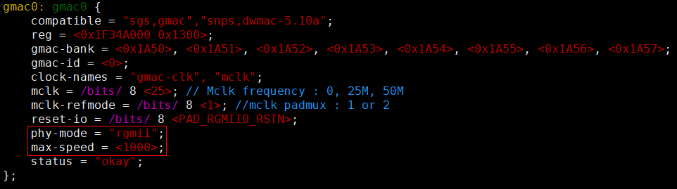
Figure 5-1 UBOOT GMAC0 RGMII DTS (default) Release the pinmux of "gmac0" and set it as shown below. It needs to be changed to "#if 1":
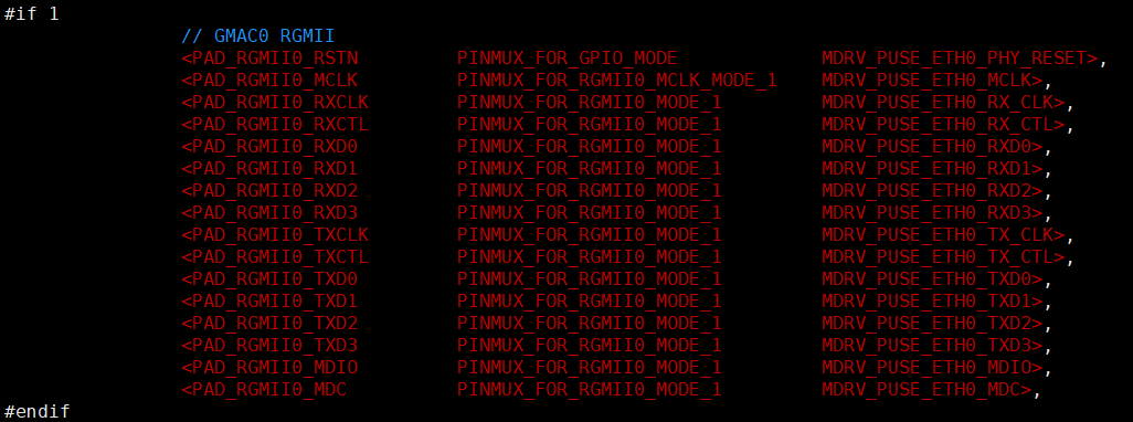
Figure 5-2 UBOOT GMAC0 RGMII PINMUX (default) -
GMAC1 is configured as rgmii
Modify the "gmac1" dts node and change the phy-mode to "rgmii". The setting example is as follows:
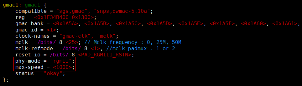
Figure 5-3 UBOOT GMAC1 RGMII DTS Release the pinmux of "gmac1" and set it as shown below. It needs to be changed to "#if 1":
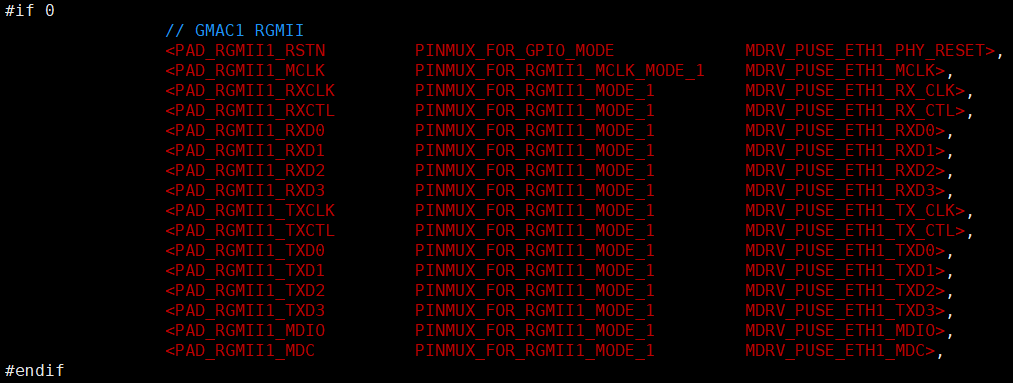
Figure 5-4 UBOOT GMAC1 RGMII PINMUX
5.2.3.1 CONFIG Configuration
RTL8211 uses Generic PHY Driver by default, no need to enable config. Take GMAC0 RGMII as an example, configure according to Figure 5-1 and Figure 5-2 to use it normally.
5.2.3.2 PHY DRIVER Path
5.2.4 Configure DTS to RMII (external Ephy)
-
Configure GMAC0 to rmii
Modify the "gmac0" dts node, change phy-mode to "rmii", max-speed =
<100>, the setting example is as follows: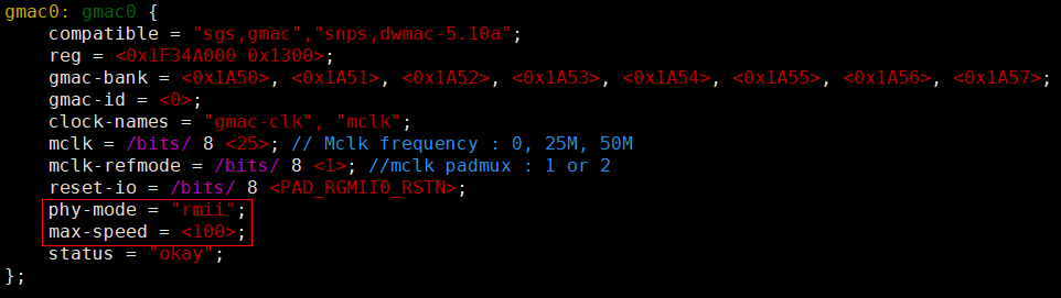
Figure 5-5 UBOOT GMAC0 RMII DTS Release the pinmux of "gmac0" and set it as shown below. It needs to be changed to "#if 1":
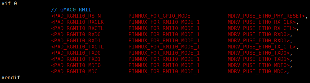
Figure 5-6 UBOOT GMAC0 RMII PINMUX -
GMAC0 is configured as rmii
Modify the "gmac1" dts node, change phy-mode to "rmii", max-speed =
<100>, the setting example is as follows: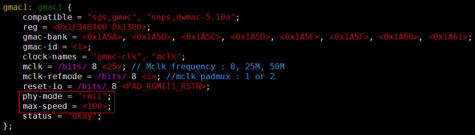
Figure 5-7 UBOOT GMAC1 RMII DTS Release the pinmux of "gmac1" and set it as shown below. It needs to be changed to "#if 1":
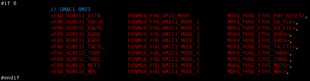
Figure 5-8 UBOOT GMAC1 RMII PINMUX
5.2.4.1 CONFIG configuration
If there is no special requirement for the PHY used, you can use the default Generic PHY Driver without enabling config.
5.2.4.2 PHY DRIVER path
5.3. Uboot cmd parameter description
Uboot mainly uses ping dhcp tftp commands for network. Before using these commands, you need to configure the environment variables used by the network.
5.3.1 ENV configuration uses static IP of GMAC0
setenv -f ethact gmac0
setenv -f ethaddr xx:xx:xx:xx:xx:xx
setenv -f ipaddr xxx.xxx.xxx.xxx
setenv -f netmask xxx.xxx.xxx.xxx
setenv -f serverip xxx.xxx.xxx.xxx
5.3.2 ENV configuration uses static IP of GMAC1
setenv -f ethact gmac1
setenv -f eth1addr xx:xx:xx:xx:xx:xx
setenv -f ipaddr xxx.xxx.xxx.xxx
setenv -f netmask xxx.xxx.xxx.xxx
setenv -f serverip xxx.xxx.xxx.xxx
5.3.3 ENV configuration using dynamic IP of GMAC0
5.3.4 ENV configuration using dynamic IP of GMAC1
5.4 Uboot cmd usage examples
5.4.1 Ping cmd demonstration
 # set -f ethaddr 00:00:83:94:00:01
 # set -f serverip 10.21.2.38
 # set -f ipaddr 10.24.16.142
 # save
 # ping 10.21.2.38
Using gmac0 device
host 10.21.2.38 is alive
5.4.2 dhcp cmd demonstration
 # set -f ethaddr 00:00:83:94:00:01
 # set -f serverip 10.21.2.38
 # save
Saving Environment to NAND...
ENV: offset = 0x500000 size = 0x40000
Erasing NAND...
Erasing at 0x520000 -- 100% complete.
Writing to NAND... OK
OK
 # dhcp
gmac0 Waiting for PHY auto negotiation to complete....... done
BOOTP broadcast 1
BOOTP broadcast 2
BOOTP broadcast 3
BOOTP broadcast 4
BOOTP broadcast 5
BOOTP broadcast 6
DHCP client bound to address 10.24.16.142 (5778 ms)
5.4.3 tftp cmd demonstration
 # tftp 0x21000000 boot.bin
Using gmac0 device
TFTP from server 10.21.2.38; our IP address is 10.24.16.142; sending through gateway 10.24.16.254
Filename 'boot.bin'.
Load address: 0x21000000
Loading: T #################################################################
     ##################################
     237.3 KiB/s
done
Bytes transferred = 1441792 (160000 hex)
6. Kernel Usage Introduction
6.1. Kernel Config Configuration
-
GMAC module needs to enable STMICRO & SGS GMAC
-
STMICRO (enabled by default)
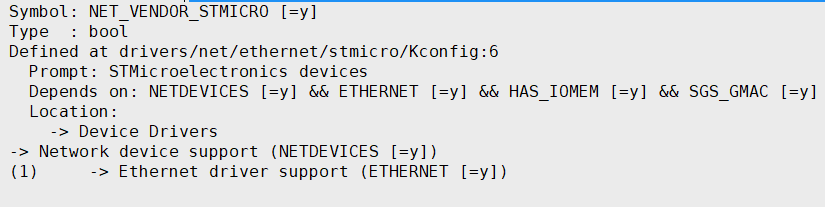
Figure 6-1 KERNEL STMICRO -
SGS GMAC (enabled by default)
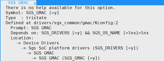
Figure 6-2 KERNEL SGS GMAC
6.2. Dts configuration parameter description
-
gmac0 dts node:
gmac0 { compatible = "sgs,gmac","snps,dwmac-5.10a"; //interrupts = <GIC_SPI INT_IRQ_NET_GP_TOP0 IRQ_TYPE_LEVEL_HIGH>; interrupts = <GIC_SPI INT_IRQ_GMAC0 IRQ_TYPE_LEVEL_HIGH>; interrupt-names = "macirq"; reg = <0x0 0x1F34A000 0x1300>; reset-io = /bits/ 8 <PAD_RGMII0_RSTN>; gmac-id = <0>; gmac-bank = <0x1A50>, <0x1A51>, <0x1A52>, <0x1A53>, <0x1A54>, <0x1A55>, <0x1A56>, <0x1A57>; mclk = /bits/ 8 <25>; // Mclk frequency : 0, 25M, 50M disable-txfc = /bits/ 8 <1>; clocks = <&CLK_gmac0_gmii>, <&CLK_gphy0_ref>; clock-names = "gmac-clk", "mclk"; snps,tso; phy-handle = <&phy0>; phy-mode = "rgmii"; max-speed = <1000>; //snps,txpbl = <16>; //snps,rxpbl = <16>; //snps,aal; status = "ok"; mdio-bus@gmac0 { compatible = "snps,dwmac-mdio"; phy0: ethernet-phy@0 { }; }; }; -
gmac1 dts node :
gmac1 { compatible = "sgs,gmac","snps,dwmac-5.10a"; //interrupts = <GIC_SPI INT_IRQ_NET_GP_TOP0 IRQ_TYPE_LEVEL_HIGH>; interrupts = <GIC_SPI INT_IRQ_GMAC1 IRQ_TYPE_LEVEL_HIGH>; interrupt-names = "macirq"; reg = <0x0 0x1F34B400 0x1300>; reset-io = /bits/ 8 <PAD_RGMII1_RSTN>; gmac-id = <1>; gmac-bank = <0x1A5A>, <0x1A5B>, <0x1A5C>, <0x1A5D>, <0x1A5E>, <0x1A5F>, <0x1A60>, <0x1A61>; mclk = /bits/ 8 <25>; // Mclk frequency : 0, 25M, 50M disable-txfc = /bits/ 8 <1>; clocks = <&CLK_gmac1_gmii>, <&CLK_gphy1_ref>; clock-names = "gmac-clk", "mclk"; snps,tso; phy-handle = <&phy1>; phy-mode = "rgmii"; max-speed = <1000>; //snps,txpbl = <16>; //snps,rxpbl = <16>; //snps,aal; status = "disabled"; mdio-bus@gmac1 { compatible = "snps,dwmac-mdio"; phy1: ethernet-phy@1 { }; }; }; -
The gmac dts nodes are shown above, and their meanings are:
Parameter Definition Remark compatible Property information, driver version information interrupts Interrupt pin interrupt-names Interrupt name reg Physical address of register mapping reset-io phy reset pin gmac-id gmac number gmac-bank Bank address corresponding to register mclk Configure whether to output mclk 0: No output; 25: Output 25MHz disable-txfc Whether to turn off hardware flow control 1: Turn off; 0: Enable enable-eee Whether to turn on EEE function 1: Enable; 0: Turn off clocks Clock nodes used by gmac clocks-name The name of the clock used by gmac snps,tso Enable TSO, i.e. TCP Segment Offload Comment this line to disable TSO phy-handle phy node phy-mode The phy interface provides three interface options "rmii"/"rgmii" max-speed Limit the maximum rate under auto-negotiation, three gear options <10>/<100>/<1000>snps,txpbl snps sets tx burst snps,rxpbl snps sets rx burst snps,aal Address alignment (Address-Aligned) status Driver switch "ok"/"disabled" -
mclk-refmode currently only supports RGMIIX_MCLK output.
-
To force speed and full/half duplex, you need to add fixed-link control with the following content:
Parameter Definition Remark speed indicating that the connection speed has 10, 100, 1000 to choose from integer, required full-duplex indicating whether it is full-duplex, if it is not filled in, it means half-duplex optional pause indicating the enablement of asym-pause optional link-gpios indicating whether the gpio can be read to determine whether the link is normal "gpio-list", optional For example: fixed-link { speed = <100>; full-duplex; pause; }The above example means forcing 100M full-duplex.
Note:
When RMII is connected to a 100M switch, force 100 full-duplex must be used.
When RGMII is connected to a 1000M switch, force 1000 full-duplex must be used.
-
mclk (If you want to save the external crystal oscillator of PHY, you can let the main control chip generate clock for PHY)
mclk: Specifiable frequency, 0: no clock, 25: output 25MHz
mclk signal is output through PAD_RGMII0_MCLK
-
disable-txfc: whether to turn off hardware tx flow control
<0>: Enable tx flow control<1>: Disable tx flow control
6.3 Padmux Configuration
Add the following code to the corresponding padmux.dtsi according to the selected pin:
-
RGMII PADMUX configuration of GMAC0:
// GMAC0 RGMII <PAD_RGMII0_RSTN PINMUX_FOR_GPIO_MODE MDRV_PUSE_ETH0_PHY_RESET>, <PAD_RGMII0_MCLK PINMUX_FOR_RGMII0_MCLK_MODE_1 MDRV_PUSE_ETH0_MCLK>, <PAD_RGMII0_RXCLK PINMUX_FOR_RGMII0_MODE_1 MDRV_PUSE_ETH0_RX_CLK>, <PAD_RGMII0_RXCTL PINMUX_FOR_RGMII0_MODE_1 MDRV_PUSE_ETH0_RX_CTL>, <PAD_RGMII0_RXD0 PINMUX_FOR_RGMII0_MODE_1 MDRV_PUSE_ETH0_RXD0>, <PAD_RGMII0_RXD1 PINMUX_FOR_RGMII0_MODE_1 MDRV_PUSE_ETH0_RXD1>, <PAD_RGMII0_RXD2 PINMUX_FOR_RGMII0_MODE_1 MDRV_PUSE_ETH0_RXD2>, <PAD_RGMII0_RXD3 PINMUX_FOR_RGMII0_MODE_1 MDRV_PUSE_ETH0_RXD3>, <PAD_RGMII0_TXCLK PINMUX_FOR_RGMII0_MODE_1 MDRV_PUSE_ETH0_TX_CLK>, <PAD_RGMII0_TXCTL PINMUX_FOR_RGMII0_MODE_1 MDRV_PUSE_ETH0_TX_CTL>, <PAD_RGMII0_TXD0 PINMUX_FOR_RGMII0_MODE_1 MDRV_PUSE_ETH0_TXD0>, <PAD_RGMII0_TXD1 PINMUX_FOR_RGMII0_MODE_1 MDRV_PUSE_ETH0_TXD1>, <PAD_RGMII0_TXD2 PINMUX_FOR_RGMII0_MODE_1 MDRV_PUSE_ETH0_TXD2>, <PAD_RGMII0_TXD3 PINMUX_FOR_RGMII0_MODE_1 MDRV_PUSE_ETH0_TXD3>, <PAD_RGMII0_MDIO PINMUX_FOR_RGMII0_MODE_1 MDRV_PUSE_ETH0_MDIO>, <PAD_RGMII0_MDC PINMUX_FOR_RGMII0_MODE_1 MDRV_PUSE_ETH0_MDC>, -
RMII PADMUX configuration for GMAC0:
// GMAC0 RMII <PAD_RGMII0_RSTN PINMUX_FOR_GPIO_MODE MDRV_PUSE_ETH0_PHY_RESET>, <PAD_RGMII0_RXCLK PINMUX_FOR_RMII0_MODE_1 MDRV_PUSE_ETH0_RX_CLK>, <PAD_RGMII0_RXCTL PINMUX_FOR_RMII0_MODE_1 MDRV_PUSE_ETH0_RX_CTL>, <PAD_RGMII0_RXD0 PINMUX_FOR_RMII0_MODE_1 MDRV_PUSE_ETH0_RXD0>, <PAD_RGMII0_RXD1 PINMUX_FOR_RMII0_MODE_1 MDRV_PUSE_ETH0_RXD1>, <PAD_RGMII0_TXCTL PINMUX_FOR_RMII0_MODE_1 MDRV_PUSE_ETH0_TX_CTL>, <PAD_RGMII0_TXD0 PINMUX_FOR_RMII0_MODE_1 MDRV_PUSE_ETH0_TXD0>, <PAD_RGMII0_TXD1 PINMUX_FOR_RMII0_MODE_1 MDRV_PUSE_ETH0_TXD1>, <PAD_RGMII0_MDIO PINMUX_FOR_RMII0_MODE_1 MDRV_PUSE_ETH0_MDIO>, <PAD_RGMII0_MDC PINMUX_FOR_RMII0_MODE_1 MDRV_PUSE_ETH0_MDC>, -
RGMII PADMUX configuration for GMAC1:
// GMAC1 RGMII <PAD_RGMII1_RSTN PINMUX_FOR_GPIO_MODE MDRV_PUSE_ETH1_PHY_RESET>, <PAD_RGMII1_MCLK PINMUX_FOR_RGMII1_MCLK_MODE_1 MDRV_PUSE_ETH1_MCLK>, <PAD_RGMII1_RXCLK PINMUX_FOR_RGMII1_MODE_1 MDRV_PUSE_ETH1_RX_CLK>, <PAD_RGMII1_RXCTL PINMUX_FOR_RGMII1_MODE_1 MDRV_PUSE_ETH1_RX_CTL>, <PAD_RGMII1_RXD0 PINMUX_FOR_RGMII1_MODE_1 MDRV_PUSE_ETH1_RXD0>, <PAD_RGMII1_RXD1 PINMUX_FOR_RGMII1_MODE_1 MDRV_PUSE_ETH1_RXD1>, <PAD_RGMII1_RXD2 PINMUX_FOR_RGMII1_MODE_1 MDRV_PUSE_ETH1_RXD2>, <PAD_RGMII1_RXD3 PINMUX_FOR_RGMII1_MODE_1 MDRV_PUSE_ETH1_RXD3>, <PAD_RGMII1_TXCLK PINMUX_FOR_RGMII1_MODE_1 MDRV_PUSE_ETH1_TX_CLK>, <PAD_RGMII1_TXCTL PINMUX_FOR_RGMII1_MODE_1 MDRV_PUSE_ETH1_TX_CTL>, <PAD_RGMII1_TXD0 PINMUX_FOR_RGMII1_MODE_1 MDRV_PUSE_ETH1_TXD0>, <PAD_RGMII1_TXD1 PINMUX_FOR_RGMII1_MODE_1 MDRV_PUSE_ETH1_TXD1>, <PAD_RGMII1_TXD2 PINMUX_FOR_RGMII1_MODE_1 MDRV_PUSE_ETH1_TXD2>, <PAD_RGMII1_TXD3 PINMUX_FOR_RGMII1_MODE_1 MDRV_PUSE_ETH1_TXD3>, <PAD_RGMII1_MDIO PINMUX_FOR_RGMII1_MODE_1 MDRV_PUSE_ETH1_MDIO>, <PAD_RGMII1_MDC PINMUX_FOR_RGMII1_MODE_1 MDRV_PUSE_ETH1_MDC>, -
RMII PADMUX configuration of GMAC1:
// GMAC1 RMII
<PAD_RGMII1_RSTN         PINMUX_FOR_GPIO_MODE            MDRV_PUSE_ETH1_PHY_RESET>,
<PAD_RGMII1_RXCLK        PINMUX_FOR_RMII1_MODE_1         MDRV_PUSE_ETH1_RX_CLK>,
<PAD_RGMII1_RXCTL        PINMUX_FOR_RMII1_MODE_1         MDRV_PUSE_ETH1_RX_CTL>,
<PAD_RGMII1_RXD0         PINMUX_FOR_RMII1_MODE_1         MDRV_PUSE_ETH1_RXD0>,
<PAD_RGMII1_RXD1         PINMUX_FOR_RMII1_MODE_1         MDRV_PUSE_ETH1_RXD1>,
<PAD_RGMII1_TXCTL        PINMUX_FOR_RMII1_MODE_1         MDRV_PUSE_ETH1_TX_CTL>,
<PAD_RGMII1_TXD0         PINMUX_FOR_RMII1_MODE_1         MDRV_PUSE_ETH1_TXD0>,
<PAD_RGMII1_TXD1         PINMUX_FOR_RMII1_MODE_1         MDRV_PUSE_ETH1_TXD1>,
<PAD_RGMII1_MDIO         PINMUX_FOR_RMII1_MODE_1         MDRV_PUSE_ETH1_MDIO>,
<PAD_RGMII1_MDC          PINMUX_FOR_RMII1_MODE_1         MDRV_PUSE_ETH1_MDC>,
6.4. DTS node PHY switching example
6.4.1 KERNEL GMAC RGMII (external Gphy RTL8211)
-
DTS configuration: usage is the same as UBOOT, phy-mode is configured as rgmii, max-speed is configured as 1000, and pinmux needs to be released
-
CONFIG configuration: RTL8211 uses Generic PHY Driver by default, no need to enable it
-
PHY Driver path: drivers/net/phy/phy_device.c
6.4.2 KERNEL GMAC RMII (external Ephy)
-
DTS configuration: usage is the same as UBOOT, phy-mode configures rmii, max-speed is configured to 100, pinmux needs to be released
-
CONFIG configuration: if there is no special requirement for the PHY used, the default Generic PHY Driver can be used
-
PHY Driver path: drivers/net/phy/phy_device.c
6.5. Kernel modular configuration
6.5.1 Kernel Config configuration
-
GMAC related: Set SGS_GMAC = m, refer to the following configuration, and sgs_gmac.ko will be generated after compilation.
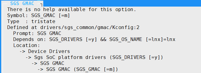
Figure 6-4 SGS_GMAC modular -
stmmac: Set STMMAC_ETH = m and STMMAC_PLATFORM = m. Refer to the following configuration. After compilation, phylink.ko/mii.ko/stmmac.ko/stmmac-platform.ko will be generated.
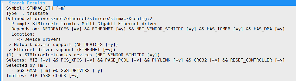
Figure 6-5 STMMAC_ETH modular 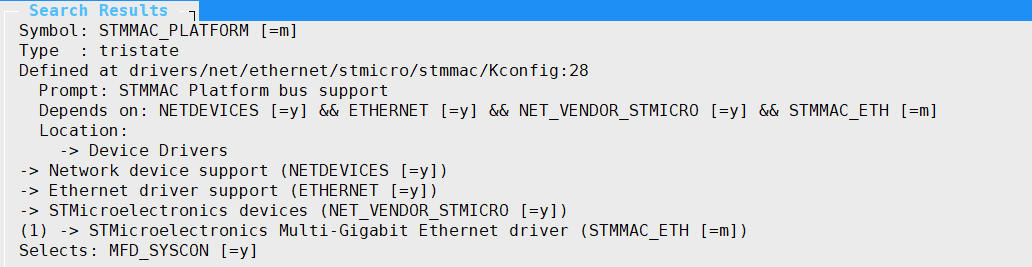
Figure 6-6 STMMAC_PLATFORM modular
6.5.2 ko loading order
insmod stmmac.ko
insmod stmmac-platform.ko
insmod sgs_gmac.ko
6.6. Kernel cmd usage examples
-
View all network card information
ifconfig -a -
eth0 network card enabled
ifconfig eth0 up -
Configure the MAC address of the network card eth0 to 00:00:83:94:40:01
ifconfig eth0 hw ether 00:00:83:94:40:01 -
Configure the static IP address of network card eth0 to 40.1.1.1/24
ifconfig eth0 40.1.1.1 netmask 255.255.255.0
-Network card eth0 dhcp obtain ip
udhcpc -i eth0 -s /etc/init.d/udhcpc.script
-
Mount nfs directory
mount -t nfs -o nolock xxx.xxx.xxx.xxx:/c/nfs /mntParameter Description xxx.xxx.xxx.xxx nfs server IP address /c/nfs nfs server directory path /mnt Mount the nfs directory on the /mnt path of the device -
Mount the cifs directory
mount -t cifs //xxx.xxx.xxx.xxx/cifs /mnt -o username=xxx,password=xxx,sec=ntlm,iocharset=utf8,vers=1.0Parameter Description xxx.xxx.xxx.xxx cifs server IP address /cifs cifs server shared directory path /mnt Mount the cifs directory on the device's /mnt path -
tftp get
tftp -g xxx.xxx.xxx.xxx -r kernelParameter Description -g xxx.xxx.xxx.xxx Get the file from server_ip xxx.xxx.xxx.xxx -r file_name The file name to be obtained from the server -
tftp put
tftp -p xxx.xxx.xxx.xxx -r kernelParameter Description -p xxx.xxx.xxx.xxx Transfer files to xxx.xxx.xxx.xxx -r file_name The name of the file to be transferred to the server
6.7. Common third-party tools and common commands
6.7.1. iperf3
-
iperf3 server mode
./iperf3 -s -i 1Option Description -s Server mode -i 1 Print echo interval (unit: seconds), here is 1 second -
iperf3 client mode
./iperf3 -c xxx.xxx.xxx.xxx -i 1 -t 36000 -b 95MOption Description -c Client mode xxx.xxx.xxx.xxx IP address of the other end -i 1 Print echo interval, in seconds, here is 1 second -t 36000 Streaming time, in seconds, maximum 86400 (24 hours) -b 95M Streaming rate 95Mbits/sec
6.7.2. tcpdump
-
Capture the packets of eth0 network card using tcpdump and cache them to pkt.cap
./tcpdump -s 0 -i eth0 -w /tmp/pkt.capOption Description -s 0 Specifies the size of the captured packet, 0 means no limit -i eth0 Indicates the connected interface, any means all interfaces -w /tmp/pkt.cap Indicates that the captured packet is written to the specified path. The file is .pcap
6.7.3. ethtool
-
View eth0 network card information
ethtool eth0 -
Switch eth0 network card speed and duplex mode
ethtool -s eth0 speed 100 duplex full -
Enable/disable eth0 auto-negotiation
ethtool -s eth0 autoneg on/off -
Enable flow control
ethtool -A eth0 rx on tx on -
View eth0 packet receiving statistics
ethtool -S eth0
6.7.4. phytool
-
Read the value of phy reg
read IFACE/ADDR/REGoptions description IFACE eth0 or eth1 ADDR Location on mdio bus REG Read phy reg eg: Read eth0 addr0 reg2
phytool read eth0/0/2 -
Write value to phy reg
write IFACE/ADDR/REG <0-0xffff>parameters description IFACE eth0 or eth1 ADDR Location on mdio bus REG Write phy reg <0-0xffff>Value to write eg: Write loopback bit of eth0
phytool write eth0/0/0 4000
6.8. Commonly used DEBUG nodes
6.8.1. phy_wr phy read and write debug nodes
- Usage
# cat phy_wr
Usage:
        echo phy_r phyid phyaddress > phy_wr
        echo phy_w phyid phyaddress phyvalue > phy_wr

eg:
    / # echo phy_r 0 0 > /proc/gmac_0/phy_wr
    phy_r phy_id[0] address[0] value[1040]
    / # echo phy_w 0 0 0x1000 > /proc/gmac_0/phy_wr
    phy_w phy_id[0] address[0] value[1000]
    / # echo phy_r 0 0 > /proc/gmac_0/phy_wr
    phy_r phy_id[0] address[0] value[1000]
6.8.2. driving capability debugging node
-
Uboot Usage
gmac drv <gmac number> <io index> <gear> <gmac number> = 0: gmac0 , 1: gmac1 <io index> = from 0 to 7 mapping to GMAC_MDC, GMAC_MDIO, GMAC_RGMII_TX_CLK, GMAC_RGMII_TX_D0, GMAC_RGMII_TX_D1, GMAC_RGMII_TX_D2, GMAC_RGMII_TX_D3, GMAC_RGMII_TX_CTL, GMAC_RGMII_MCLK, <gear> = driving gear, from 0 to (4 or 15) eg: # gmac drv 0 3 2 GMAC[0] : RGMII_TX_CLK driving changed to gear 2 -
Kernel Usage
cat driving => show current driving
echo [io_idx] [gear] > driving => Set the [io_idx] to [gear] level, 0 <= gear < 4

eg:
    / # cat /proc/gmac_0/driving
    gmac0 driving:
    index 0 MDC = 1
    index 1 MDIO = 1
    index 2 MCLK = 0
    index 3 RGMII_TX_CLK = 1
    index 4 RGMII_TX_D0 = 1
    index 5 RGMII_TX_D1 = 1
    index 6 RGMII_TX_D2 = 1
    index 7 RGMII_TX_D3 = 1
    index 8 RGMII_TX_CTL = 1
    / # echo 3 2 > /proc/gmac_0/driving
    RGMII_TX_CLK driving = 2
    / # cat /proc/gmac_0/driving
    gmac0 driving:
    index 0 MDC = 1
    index 1 MDIO = 1
    index 2 MCLK = 0
    index 3 RGMII_TX_CLK = 2
    index 4 RGMII_TX_D0 = 1
    index 5 RGMII_TX_D1 = 1
    index 6 RGMII_TX_D2 = 1
    index 7 RGMII_TX_D3 = 1
    index 8 RGMII_TX_CTL = 1
7. API Reference
GMAC has no external API
8. FAQ
Q1: Failed to scan phy at startup
The root cause of this problem is abnormal mdio read and write or phy initialization failure, so there are several points to check:
-
Check whether the RMII/RGMII pin configuration in padmux.dtsi is turned on, and confirm whether there is a conflict in the pin configuration.
-
Confirm the reset timing of the phy used. At the same time, it is necessary to confirm whether the time to maintain the level meets the requirements of phy.
-
If the phy used is not supported by the public version, you need to find the corresponding phy manufacturer to confirm whether a dedicated phy driver support is required.
-
Check whether the hardware wiring is correct, whether there is any wrong connection, cold soldering, short circuit, etc.
Q2: The device has a lot of packet loss and the network rate cannot be increased
-
It is necessary to check whether the link mode of the device and the other end is consistent. You can use the "./ethtool eth0" command to view the current phy link mode
-
It is necessary to check whether the physical connection of the network cable is loose and whether the quality of the network cable itself is qualified
-
Check whether the network environment is normal, such as whether the firewall is turned on, whether the transit device (router, switch) has a qos policy that affects the bandwidth, etc. It can be changed to a direct connection environment verification and troubleshooting (such as DUT directly connected to the PC).
-
Check whether the CPU load of the device is too large, so that the device cannot process network messages in time, resulting in packet loss.
-
Check the signal quality. You can adjust the phy end driver capability by configuring the corresponding phy register.