PQ Tool SOP
REVISION HISTORY
| Revision No. | Description | Date |
|---|---|---|
| 1.0 | 02/20/2023 | |
| 1.1 | 05/06/2023 | |
| 1.2 | 07/24/2023 |
1. PQ TOOL Configuration & Connection
1.1. Connecting the Tool
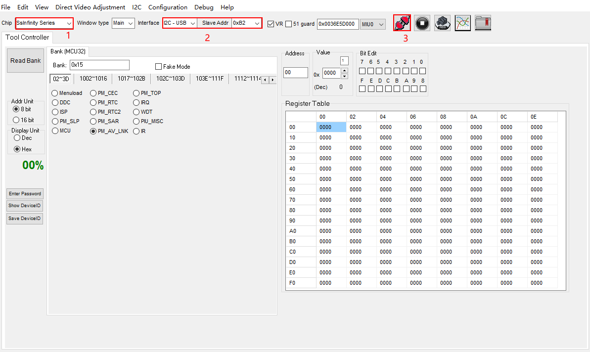
(1) Select the chip platform from the SsInfinity Series, as shown in Step 1.
(2) Close the serial printing and disconnect the serial software.
echo 1 3 1 7 > /proc/sys/kernel/printk
11111
(3) Select the I2C-USB connection method and choose the corresponding I2C address, as shown in Step 2.
(4) Check the connection, as shown in Step 3 (the red icon turns green; green indicates a successful connection; otherwise, the connection has failed; please check the serial connection).
1.2 Verify the Correctness of Connection Status
1.2.1 Confirm Connection Status
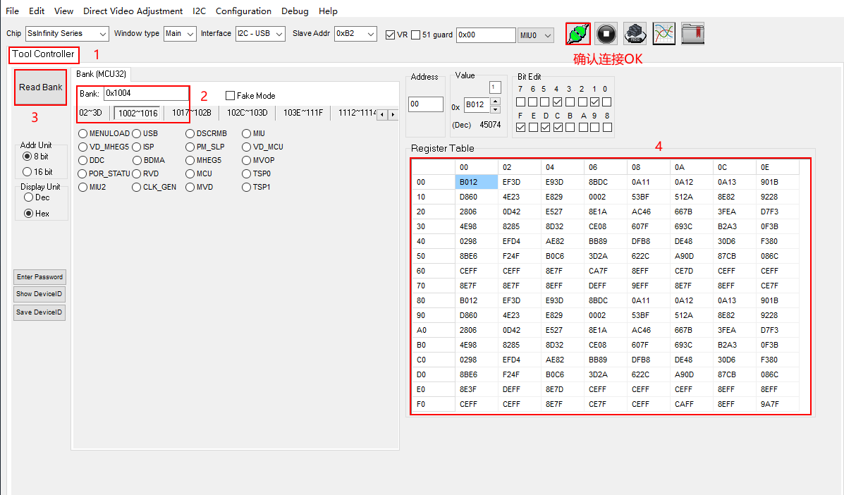
(1) Select Tool Controller, as shown in Step 1.
(2) Select the corresponding bank address, such as bank 0x1004, as shown in Step 2.
(3) Click Read Bank, as shown in Step 3.
(4) Confirm that the data in the Register Table after reading is not all 0/0xFF, which indicates normal operation, as shown in Frame 4.
2. Parameter Adjustment
2.1. Gamma Adjustment Description
2.1.1 How to Obtain the Current Gamma Value on the Board and Save Debug Parameters
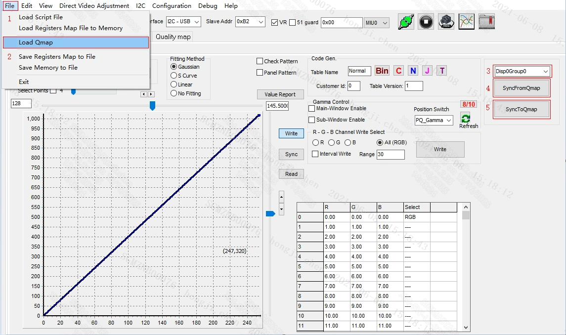
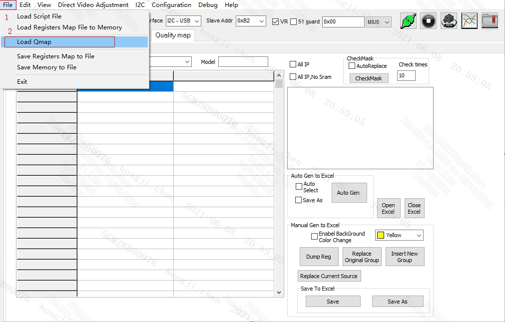
(1) Click the file dropdown, as shown in Step 1.
(2) Click Load Qmap, as shown in Step 2, to load the currently used Qmap table.
(3) If currently using disp0, use Disp0Group0 by default; if using disp1, switch to Disp1Group1, as shown in Step 3.
(4) Click the SyncFromQmap button to load the gamma curve from the Qmap table.
(5) To modify and save the adjusted gamma parameters, click the SyncToQmap button to write the current parameters into the Qmap table.
Note: After adjusting a set of Gamma, eight additional sets will automatically be generated and saved to QMAP.
2.1.2 How to Adjust the Gamma Value Online
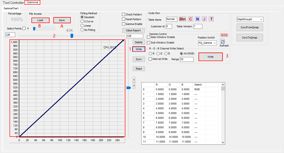
(1) Select the Write option box, as shown in Step 1.
(2) Adjust the Gamma curve (as shown in Step 2); click on the curve with the mouse to drag it. The curve can be adjusted using four methods: R/G/B/ALL, according to the actual situation of the image.
(3) Click the Write button to write the updated Gamma data to the board, as shown in Step 3.
2.1.3 Other Related Parameter Descriptions in the Gamma Option Bar
(1) Reset Method: When the Write option box is selected, if the effect of the current adjusted curve is unsatisfactory, right-click in the curve area: Reset All curve, and the curve will be reset to the default value.
(2) Option A Save button is used to save the current tool's parameter values, so they can be easily loaded later to check effects.
(3) Option B Load is used to import the saved parameter values and display them on the tool interface.
(4) The Delete option is used to delete Gamma points.
2.2 CSC Adjustment Description
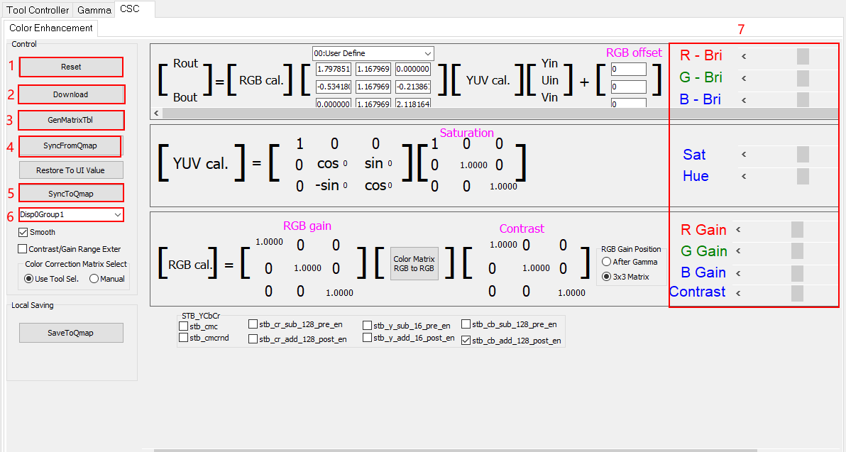
(1) The Reset button serves to restore the current parameters on the tool to their initialized values.
(2) After adjusting the corresponding values, the Download button will update the CSC settings in real-time on the board.
(3) Load the Qmap table through file->Load Qmap, and clicking SyncFromQmap will load the parameters from the Qmap table to the current interface.
(4) Click SyncToQmap to write the current parameter settings into the Qmap table.
(5) Select the Group; the default checked option is Disp0Group1.
(6) Adjust the corresponding parameter values (which are: Brightness: Bri / Saturation: Sat / Hue: Hue / Contrast: Contrast / White Balance Gain: RGB Gain).
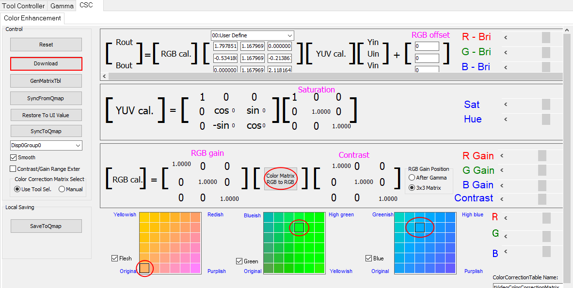
(7) Clicking the color Matrix RGB to RGB option will display the adjustment functions for R, G, and B color shifts below, as shown in the figure. Starting points default to the lower left corner origin; the color shift can be modified by dragging the box to the corresponding position. After modification, click Download on the left to make it effective. Note that this module is a fine-tuning of the above 3x3 matrix RGB gain parameters. If color deviation occurs, it can be adjusted in conjunction with the above 3x3 matrix.
(8) Click SyncToQmap to write the current parameters into the Qmap table after modifying and saving the debugged CSC parameters.
2.3 Sharpness Adjustment Description
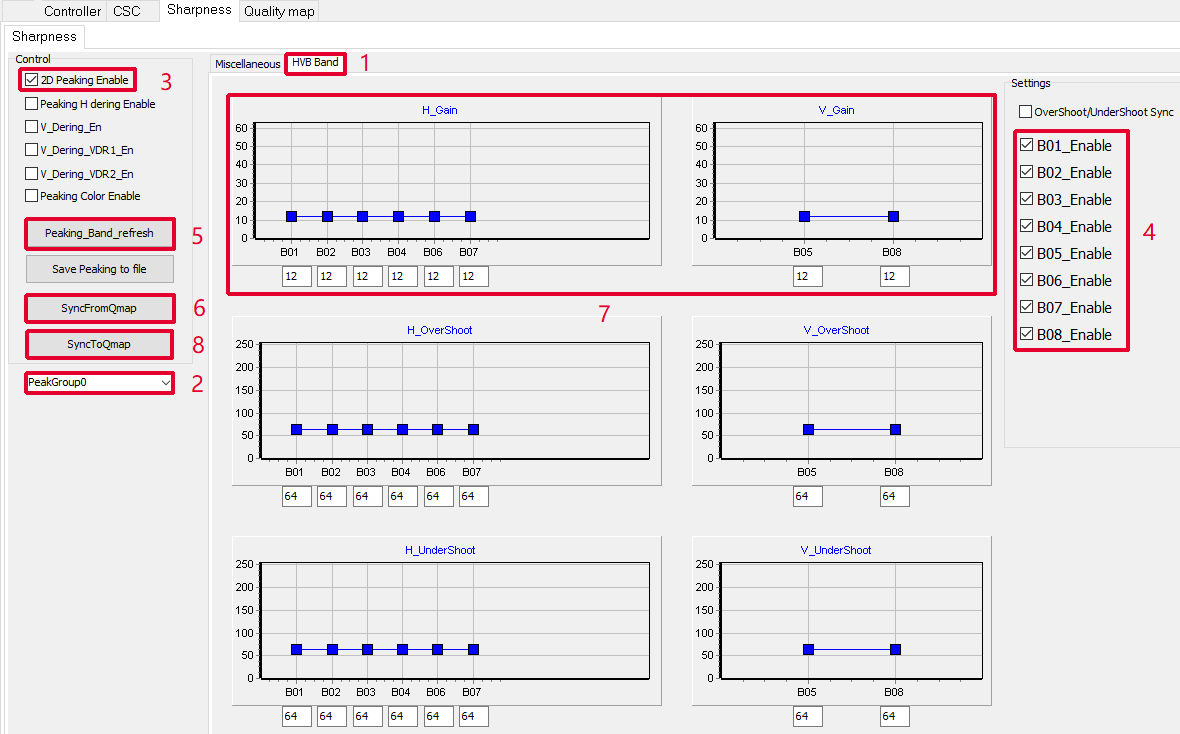
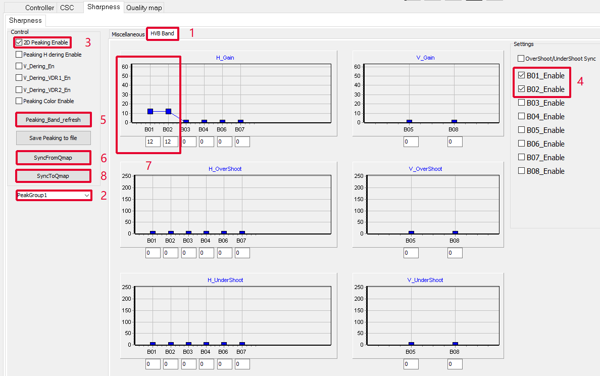
(1) Enter the Sharpness option bar and switch to the HVB Bank page, as shown in Step 1.
(2) If the current setting is Disp0, then peakgroup is peakgroup0; if it is Disp1, you need to switch to peakgroup1.
(3) Check the 2D Peaking Enable option, as shown in Step 3.
(4) Check the Band separation switch; for the Disp0 channel, check B01_Enable to B08_Enable; for the Disp1 channel, check 01_Enable and B02_Enable, as shown in Step 4.
(5) Click Peaking_Bank_refresh to refresh and display the current board's peaking parameters, as shown in Step 5.
(6) Load the Qmap table through file->Load Qmap, and click SyncFromQmap to load the parameters from the Qmap table to the current interface.
(7) Adjust H_Gain, V_Gain:
-
In the Disp0 channel, you can adjust B01-B08 to control the intensity of peaking;
B01-B04 for horizontal direction (fine to coarse), B05/B08 for vertical direction (fine/coarse), B06 and B07 for fine-tuning.
Suggestion: Mainly adjust B01-B04 + B08; B05-B07 have weaker effects and can be used as auxiliary adjustments.
-
In the Disp1 channel, only B01/B02 can be adjusted to control the intensity of peaking;
B01 is for macro control, while B02 is for fine-tuning.
Suggestion: Mainly adjust B01; B02 has a weak effect and can be used as an auxiliary adjustment.
(8) After adjusting the parameters, click SyncToQmap to write the current parameter settings into the Qmap table.
Disp0 peaking adjustment interface:
Disp1 peaking adjustment interface:
3. QMAP Table Operation Methods
3.1. Saving Parameters and Importing to the Board
(1) Before adjusting parameters, first import the currently used Qmap table via File->Load Qmap.
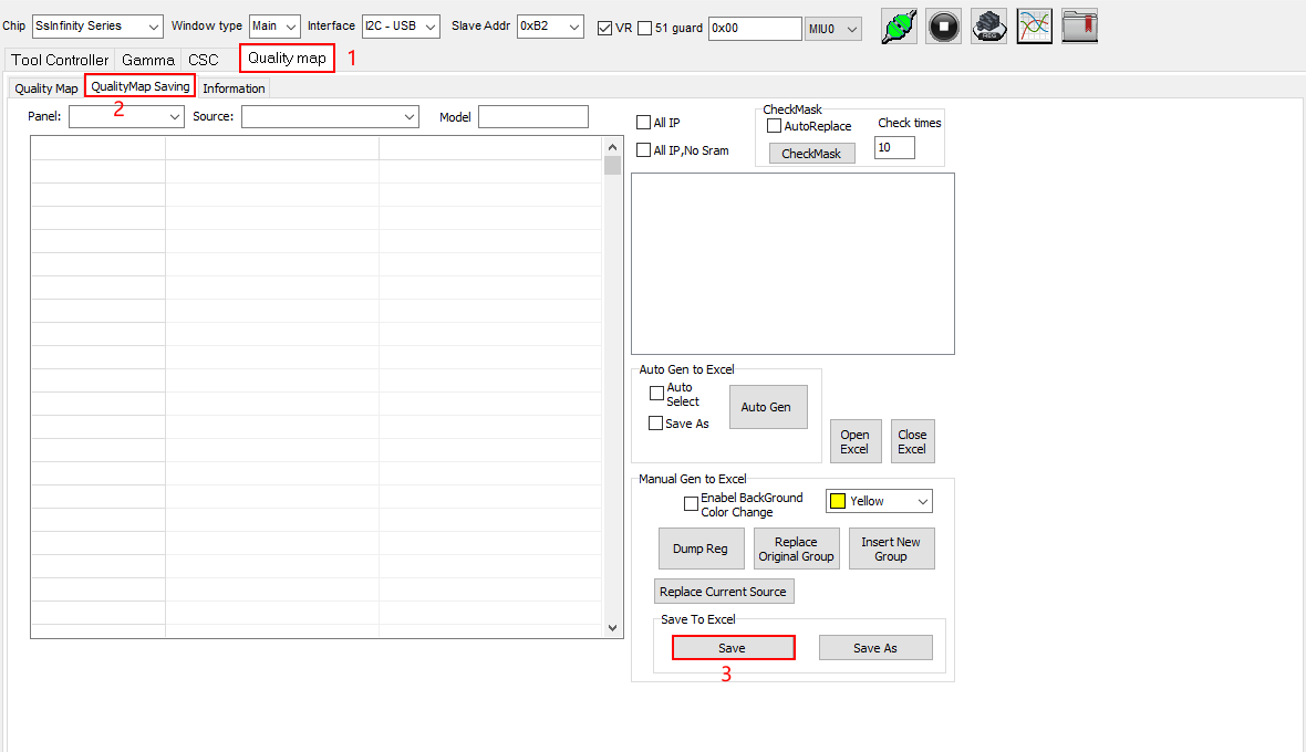
(2) Once debugging is complete and parameters are written to the QMAP table by clicking SyncToQmap on each subpage, switch to the Quality map subpage, select the QualityMap Saving option, and click the Save button to save the current local QMAP table parameters.
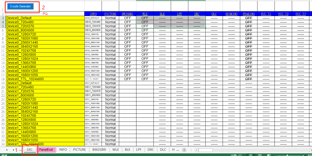
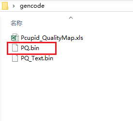
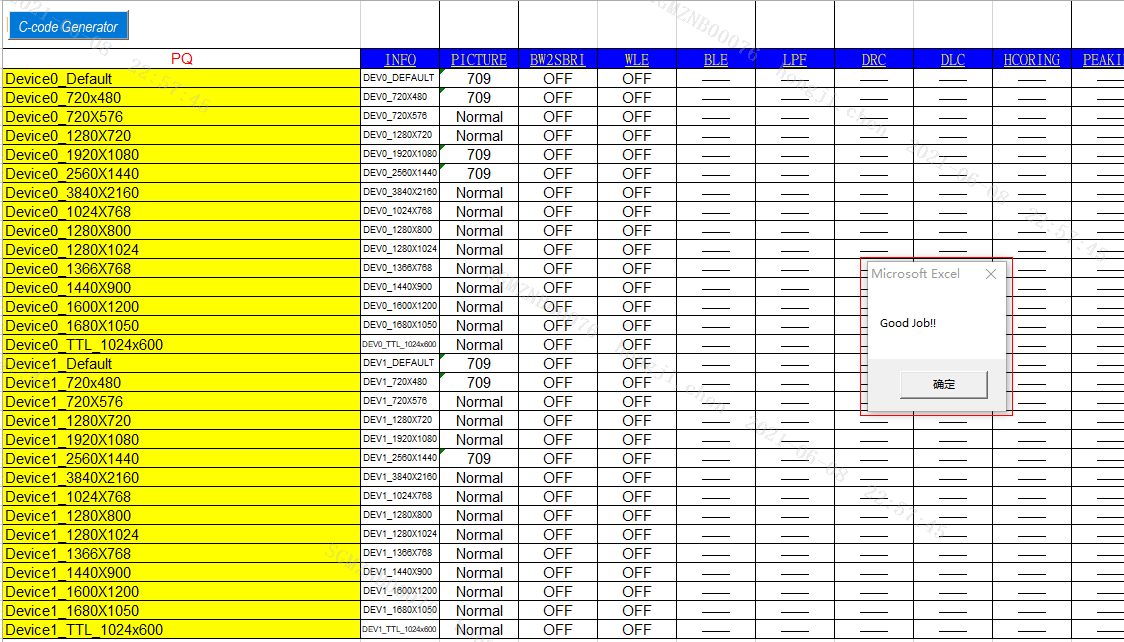
(3) Open the saved QMAP table, click the C-code Generator in the upper left corner of the SRC interface; after a while, a "Good Job" message will appear, generating a gencode path under that directory, which contains a pq.bin file. This file is the final effect parameters obtained from debugging; load this parameter to the board to take effect.
3.2. QMAP File Operation Methods and PQ.bin Generation Method
3.2.1. Manually Modify the QMAP Table to Generate PQ.bin File Effective on the System Side
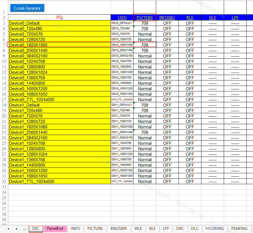
(1) Open the modified and saved local QMAP table and switch to the SRC page. Each row corresponds to different disp0, disp1 channels, and resolutions.
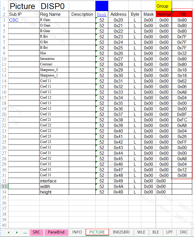
(2) Find the QMAP sub-item corresponding to the parameter modified by the PQ tool, for example, CSC corresponds to Picture in the tool.
(3) Check the corresponding columns of sub IP names where the parameters are saved. For example, saved in the Normal or 709 column.
(4) Write the Sub IP name into the box in the SRC page corresponding to the device and resolution row.
For example: Currently, under disp0 at 1920*1080 resolution, the CSC parameter was modified using the tool.
(1) CSC corresponds to the PICTURE subpage in the QMAP table.
(2) If the modified parameters saved in the 709 column after SyncToQmap, write the name of 709 into the SRC corresponding to the Device0_1920X1080 row, in the PICTURE column. (CSC parameters in the PQ tool are stored in the Normal column by default)
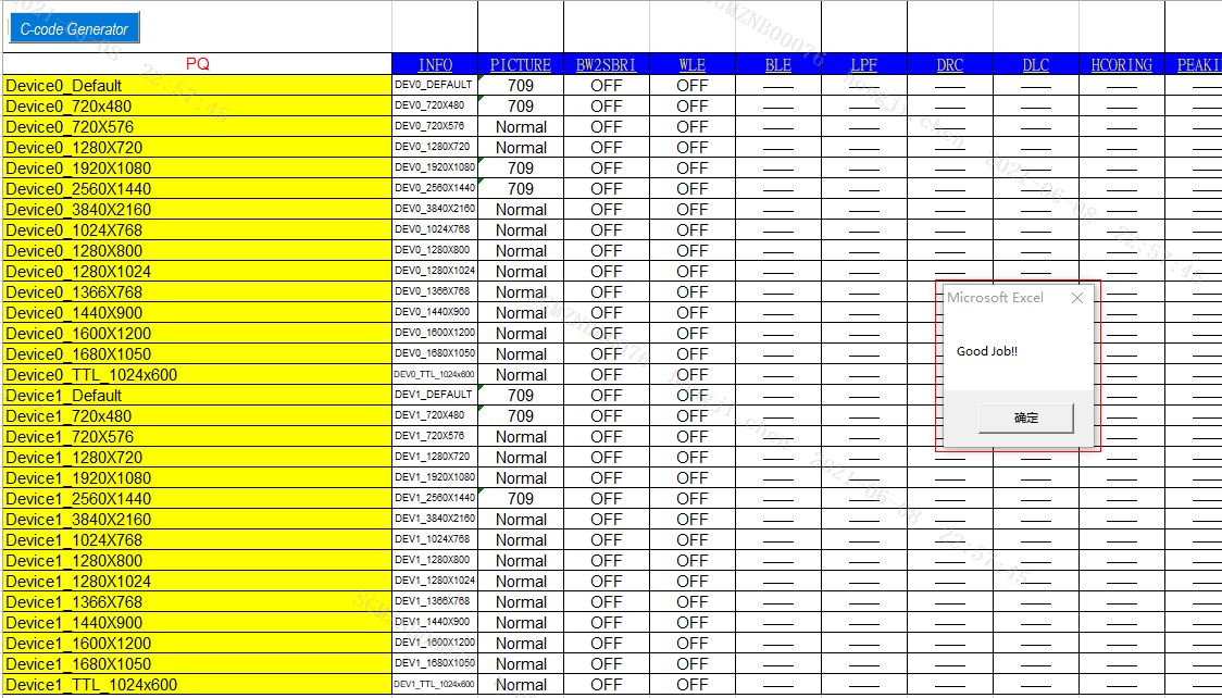
(3) Save the Qmap table, switch back to the SRC page, click C-code generator, and a gencode folder will be automatically generated in the Qmap root directory. A "Good Job!!" pop-up window will appear upon completion of file generation.
(4) Place the PQ.bin file from the gencode folder into the specified directory, and upon rebooting, parameters will automatically load into the board to take effect. For any issues, please consult the corresponding FAE.