MI VDEC API
REVISION HISTORY
| Revision No. | Description |
Date |
|---|---|---|
| 3.00 | 12/04/2020 | |
| 3.01 | MI_VDEC_PauseChn MI_VDEC_RefreshChn MI_VDEC_ResumeChn |
01/04/2021 |
| 3.02 | 02/24/2021 | |
| 3.03 | MI_VDEC_SetOutputPortAttrEx MI_VDEC_GetOutputPortAttrEx MI_VDEC_SetDestCropEx MI_VDEC_GetDestCropEx |
05/19/2021 |
| 3.04 | 07/20/2021 | |
| 08/25/2021 | ||
| 3.05 | MI_VDEC_GetEventFd MI_VDEC_CloseEventFd MI_VDEC_CloseFd MI_VDEC_SubscribeEvent MI_VDEC_UnSubscribeEvent MI_VDEC_GetEvents MI_VDEC_GetEventData MI_VDEC_ClearEvents MI_VDEC_SeqChgEvtInfo_t MI_VDEC_DecErrEvtInfo_t MI_VDEC_DecEosEvtInfo_t MI_VDEC_EventData_t MI_VDEC_Event_e |
06/15/2022 |
| 06/17/2022 | ||
| 06/17/2022 | ||
| 10/14/2022 | ||
MI_VDEC_VideoStream_t MI_VDEC_UserData_t |
10/25/2022 | |
| 3.06 | MI_VDEC_FrameDroppedEvtInfo_t E_MI_VDEC_EVENT_FRAME_DROPPED |
10/28/2022 |
| 12/01/2022 | ||
| 01/09/2023 | ||
| 3.07 | 08/29/2024 | |
| 3.08 | 09/10/2024 | |
| 10/11/2024 | ||
| 3.09 | 01/10/2025 | |
| 3.10 | 02/27/2025 | |
| 3.11 | 05/21/2025 | |
| 3.12 | 06/06/2025 | |
| 3.13 | 12/02/2025 | |
| 3.14 | 12/23/2025 | |
| 3.15 | 04/24/2026 | |
| 3.16 | 05/25/2026 | |
| 3.17 | 07/27/2026 |
1. OVERVIEW
1.1. Module Description
The video decoder module is used for fulfilling functions such as creating decoding channel, transmitting and controlling video streams, cropping and scaling output image, etc.
There are two main types of input sources for vdec module:
-
User reads stream file and sends data to decoding module
-
User sends the stream data received by the network directly to the decoding module
Table 1‑1 Chip Decoding Specifications
Chip Hardware Decoding Module Maximum Number of Channels Channel Number Range Protocol Resolution Range Max Resolution Default Taiyaki DEC2.0 16 [0, 16) H.264/H.265 H.264: max 4096x4096, min 176x128
H.265: max 4096x4096, min 176x128H.264: 4096x4096
H.265: 4096x4096Takoyaki DEC2.0 4 [0, 4) H.264/H.265 H.264: max 4096x4096, min 176x128
H.265: max 4096x4096, min 176x128H.264: 4096x4096
H.265: 4096x4096Tiramisu DEC2.0 16 [0, 16) H.264/H.265 H.264: max 4096x4096, min 176x128
H.265: max 4096x4096, min 176x128H.264: 4096x4096
H.265: 4096x4096Mochi DEC2.0 64x2 [0, 64) H.264/H.265 H.264: max 8192x4096, min 176x128
H.265: max 8192x4096, min 176x128H.264: 4704x4704
H.265: 4704x4704Muffin DEC2.0 64x2 [0, 64) H.264/H.265 H.264: max 8192x4096, min 176x128
H.265: max 8192x4096, min 176x128H.264: 3840x3840
H.265: 3840x3840Opera DEC2.0 16 [0, 16) H.264/H.265 H.264: max 8192x4096, min 176x128
H.265: max 8192x4096, min 176x128H.264: 4096x4096
H.265: 4096x4096iBopper DEC2.0 64 [0, 64) H.264/H.265 H.264: max 8192x4096, min 176x128
H.265: max 8192x4096, min 176x128H.264: 3840x3840
H.265: 3840x3840ifackel DEC1.0 1 [0, 1) H.264 H.264: max 2304x1296, min 176x128 H.264: 2304x1296 jaguar1 DEC2.0 64 [0, 64) H.264/H.265 H.264: max 8192x4096, min 176x128
H.265: max 8192x4096, min 176x128H.264: 3840x3840
H.265: 3840x3840mHera DEC3.0 64x2 [0, 128) H.264/H.265 H.264: max 8192x4320, min 176x128
H.265: max 8192x4320, min 176x128H.264: 3840x3840
H.265: 3840x3840
Note :
The resolution range is calculated based on the total number of image pixels. For example, if the decoder supports the maximum resolution of 8192x4096, then 4096x8192 in corridor mode is also supported.
If the user does not set the maximum decoding resolution, MI_VDEC uses the default maximum resolution. The maximum decoding resolution can be set by calling MI_VDEC_CreateDev. The SRAM size required for decoding matches the default maximum resolution. If the width of the maximum image set by the user exceeds the default value, the SRAM size required for decoding will also increase, it may affect other MI modules that use SRAM. Therefore, if it is not necessary, it is better to set the maximum decoding resolution back to the default maximum resolution through the API MI_VDEC_CreateDev.
The channel number range describes the range of legal values for the decoding channel number. The total number of channels that a single VDEC device can create is constrained by its maximum number of channels.
1.2. Decoding Flowchart
1.2.1. Taiyaki Data Flowchart
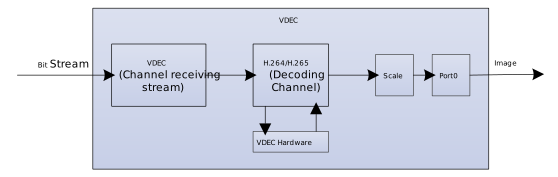
Figure 1-1: VDEC Data Flowchart
1.2.2. Takoyaki Data Flowchart
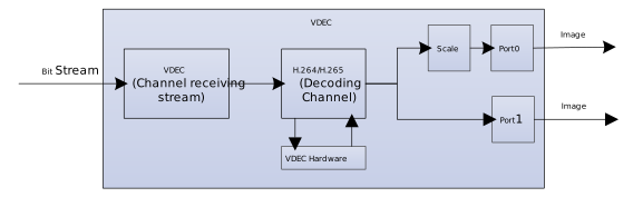
Figure 1-2: VDEC Data Flowchart
1.2.3. Tiramisu Data Flowchart
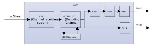
Figure 1-3: VDEC Data Flowchart
1.2.4. Muffin Data Flowchart
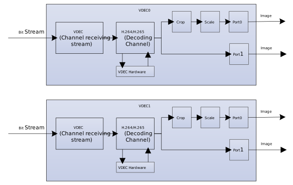
Figure 1-4: VDEC Data Flowchart
Muffin has two VDEC hardware with the same decoding capabilities, named Device0 and Device1.
1.2.5. Mochi Data Flowchart
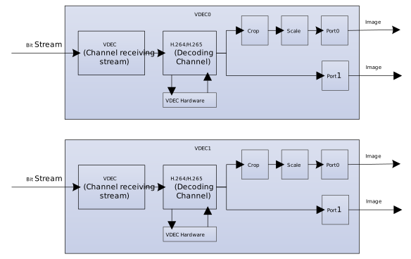
Figure 1-5: VDEC Data Flowchart
Mochi has two VDEC hardware with the same decoding capabilities, named Device0 and Device1.
1.2.6. Opera Data Flowchart
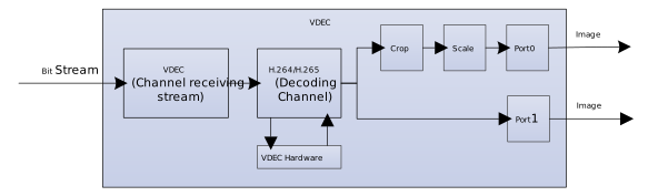
Figure 1-6: VDEC Data Flowchart
1.2.7. iBopper Data Flowchart
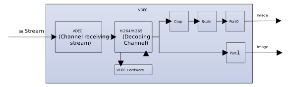
Figure 1-7: VDEC Data Flowchart
1.2.8. ifackel Data Flowchart
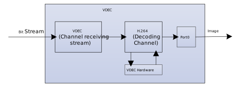
Figure 1-8: VDEC Data Flowchart
1.2.9. jaguar1 Data Flowchart
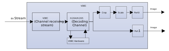
Figure 1-9: VDEC Data Flowchart
Note : Vdec do not support when VENC Device that ID is MI_VENC_DEV_ID_H264_H265_1 has created.
1.2.10. mHera Data Flowchart
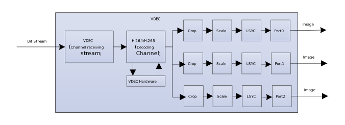
Figure 1-10: VDEC Data Flowchart
mHera has two VDEC hardware devices with the same decoding capabilities, named Device0 and Device1.
1.3. Explanation of Keywords
-
Bitstream send mode
VDEC decoder provides two ways to send bitstream:
-
Send by frame (E_MI_VDEC_VIDEO_MODE_FRAME): Each time the user sends a complete frame of video stream to the decoder and call once the send interface, the decoder considers that the frame coded stream has ended and begins to decode. Therefore, the user needs to ensure that the code stream sent each time must be a complete frame, otherwise decoding errors will occur. Using this mode can achieve the purpose of fast decoding.
-
Send by stream (E_MI_VDEC_VIDEO_MODE_STREAM): The user can send any length of bitstream to the decoder each time, and the decoding and splicing process of the bitstream frame is completed by the decoder. For H.264/H.265, the end of the current bitstream frame can only be confirmed after receiving the next bitstream. So, in this mode, the image will not be immediately output after inputting a frame of H.264/H.265 bitstream. Sending by stream is not supported.
Bitstream send mode can be set in the interface MI_VDEC_CreateChn.
-
-
Image output order
According to H.264/H.265 protocol, there are two orders to output decoded image:
-
Decoding order: the decoded image is output in the order of decoding.
-
Display order: the decoded image is output according to the display order in the protocol.
According to H.264/H.265 protocol, the decoding order of video may be inconsistent with the display order of decoded image. For example, when decoding B frame, P frame before and after B frame is needed as reference, so P frame after B frame is decoded before B frame, but B frame is output before P frame.
The VDEC decoder decides which output method to use based on the low latency parameter set by the user. When low latency is turned on, the output will be in the decoding order, which can achieve the purpose of fast output, but the decoding order and display order of the code stream must be the same to ensure the correctness of the displayed image; when low latency is not turned on, the output will be in the display order.
-
-
Low latency
The latency here refers to the latency generated by reordering the image queue to be displayed after decoding the B frame. When decoding the coded stream without B frame, the decoding order and the display order are the same, so there is no latency output, that is, the latency is low. When decoding bitstreams containing B frame, output latency will occur, because B frame has forward and backward reference, making it necessary to wait for the reference image to be decoded before the current frame can be decoded, and besides, the decoded image needs to be reordered.
These two modes need to be completed by setting bDisableLowLatency. The default value is FALSE, and the user does not need to set it. To decode bitstream with B frame, you need to set bDisableLowLatency to TRUE.
Note: The chip ifackel does not support bDisableLowLatency set to TRUE, so it will only output in the decoding order.
-
PTS
When sending a bitstream in frame mode, the decoded output image time stamp PTS is the PTS sent by the user in the MI_VDEC_SendStream interface, and the decoder will not change this value. If the PTS value set by the user is -2, the decoder will not output the frame, achieving the effect of hiding the frame. If it is another value, it means that the decoder will not do anything.
Note: PTS is not used for frame rate control. For frame rate control function, please refer to API description in MI_SYS.
-
Bitstream buffer
The bitstream buffer is used by the user to cache the coded stream input and send it to the decoder for decoding. There is no fixed formula for calculating the size of stream buffer.
Generally, according to experience, if the resolution is less than or equal to D1, the recommended value is 512KB; if the resolution is in the range (d1, 1080p], the recommended value is 1MB; if the resolution is in the range (1080p,4K], the recommended value is 2MB. Users can choose reasonable value settings according to actual needs.
-
eDpbBufMode
By setting eDpbBufMode, users can set different DPB buffer modes for decoding. According to different scenarios, different buffer modes can be selected to save memory. When E_MI_VDEC_DPB_MODE_NORMAL is set, memory cannot be saved. When E_MI_VDEC_DPB_MODE_INPLACE_ONE_BUF is set, it can only decode the stream that contains only one reference frame and only one DPB buffer is needed; when E_MI_VDEC_DPB_MODE_INPLACE_TWO_BUF is set, it can only decode the stream that contains only two reference frames and only two DPB buffer are needed.
Note: The chip ifackel does not support setting eDpbBufMode, only supports E_MI_VDEC_DPB_MODE_NORMAL.
-
u32RefFrameNum
u32refframenum represents the maximum number of reference frames. In the actual scene, the memory of the system may not be infinite. So the user can limit the number of reference frames according to the definition of the product, so as to prompt the user that the current video stream may have exceeded the specification. If the user sets eDpbBufMode to E_MI_VDEC_DPB_MODE_INPLACE_ONE_BUF or E_MI_VDEC_DPB_MODE_INPLACE_TWO_BUF, the parameter is invalid. If the user sets edpbbufmode to E_MI_VDEC_DPB_MODE_NORMAL and the number of reference frames is less than what the decoder actually needed, the decoded image may be abnormal or decoding timeout may happen.
-
Output buffer mode
The user can call MI_VDEC_SetOutputPortLayoutMode to set the output buffer mode. This interface can be called when the user needs to manually control the output buffer mode.
If E_MI_VDEC_OUTBUF_LAYOUT_LINEAR is set, it indicates that the output buffer is in linear mode.
If E_MI_VDEC_OUTBUF_LAYOUT_TILE is set, it indicates that the output buffer is in tile mode.
If E_MI_VDEC_OUTBUF_LAYOUT_AUTO is set, it indicates that the output buffer will automatically switch between linear mode and tile mode.
-
Output image format
H264 and H265 decoding only support output NV12 image format.
-
Support for H264/H265 Syntax Features
Only YUV streams with 8-bit depth is supported; H264 field mode, FMO (Flexible Macroblock Ordering), and ASO (Arbitrary Slice Ordering) are not supported.
1.4. Function Introduction
-
Output image scaling
The user can call MI_VDEC_SetOutputPortAttr to scale the decoded image to output the image with the required resolution.
Note: 1. The decoder only supports scaling down the output image. 2. The chip ifackel does not support this feature.
-
Output image cropping
The user can call MI_VDEC_SetDestCrop to crop the output image. The coordinates X and the crop width must be aligned to a certain length (chip mHera is aligned to 2, while other chips that support the crop function are aligned to 16). The coordinate Y and the height must be aligned with 2. Otherwise, the interface will return the error code MI_ERR_VDEC_ILLEGAL_PARAM. If the cropping function and the scaling function are used at the same time, follow the processing sequence of cropping first and then scaling, and the cropped image size cannot be smaller than the scaled size, otherwise the interface will return the error code MI_ERR_VDEC_ILLEGAL_PARAM.
Note: The chip ifackel does not support this feature.
The relationship between crop and scale is as shown below:
-
If neither crop nor scale is enabled, the output image will be the source resolution.

-
If crop is disabled but scale is enabled, the output image will be the same size as scaled info.

-
If crop is enabled but scale is disabled, the output image will be the same size as the cropped info.

-
If both crop and scale are enabled, the image will take the cropped size as a reference, then outputs a scaled image.

If enabling the scale, it will output the same size as the scale info.
User cropping and scaling are both performed based on the source resolution of the bitstream. If the bitstream's SPS (Sequence Parameter Set) contains crop window information, VDEC will perform an additional conversion to provide the final display area. The SPS crop window indicates the range available for display at the original resolution of the bitstream. This needs to be combined with the window situation after user cropping/scaling to obtain the final display window (Content Crop Window). The conversion formula is as follows:
content_crop_win_x = (MAX(sps_crop_x,user_crop_x)-user_crop_x)*scale_width/user_crop_widthcontent_crop_win_y = (MAX(sps_crop_y,user_crop_y)-user_crop_y)*scale_height/user_crop_heightcontent_crop_win_width = (MIN(sps_crop_x+sps_crop_width,user_crop_x+user_crop_width)-MAX(sps_crop_x,user_crop_x))*scale_width/user_crop_widthcontent_crop_win_height = (MIN(sps_crop_y+sps_crop_height,user_crop_y+user_crop_height)-MAX(sps_crop_y,user_crop_y))*scale_height/user_crop_heightIf only scaling is enabled and user cropping is not enabled, the following rules apply: user_crop_x=0, user_crop_y=0, user_crop_width=sps_width, user_crop_height=sps_height, which should be substituted into the formula.
If only user cropping is enabled and scaling is not enabled, the following rules apply: scale_width=user_crop_width, scale_height=user_crop_height, which should be substituted into the formula.
Finally, the information about the content crop window can be obtained through the stContentCropWindow in the MI_SYS_FrameData_t structure of the output buffer when low latency (bDisableLowLatency=FALSE) is enabled. Please refer to MI SYS documentation for the definition of this structure.
The following examples illustrate the process of converting to the content crop window by combining user crop and SPS crop in three scenarios:
-
Situation 1: User crop window is included in SPS crop window.
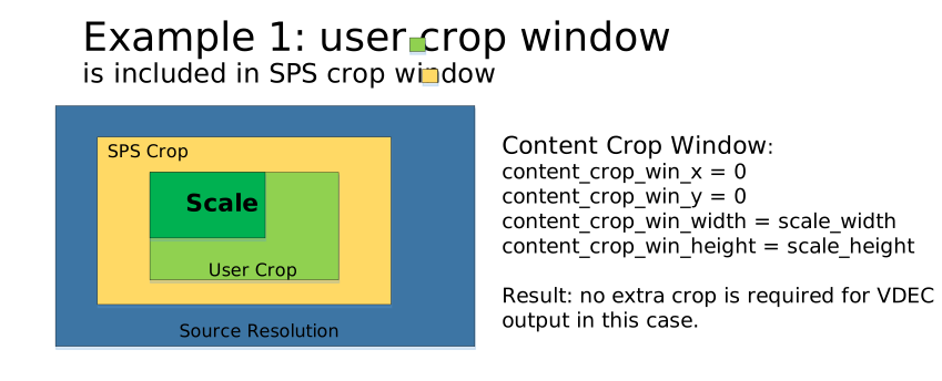
In this case, the entire user crop window is within the valid display area of the image, so no additional cropping of the VDEC output buffer is needed. The scale function is enabled in the example, so the final content crop window is the one after scaling.
-
Situation 2: User crop window is partially overlapped with SPS crop window.
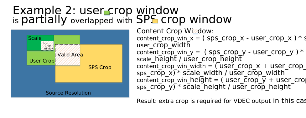
Here, only the overlapping portion of the user crop window (the Valid Area in the image) is within the valid display area of the image. Therefore, additional cropping of the VDEC output buffer is required. Since the scale function is also enabled in this example, the Valid Area needs to be scaled proportionally to obtain the content crop window.
-
Situation 3: SPS crop window is included in user crop window.
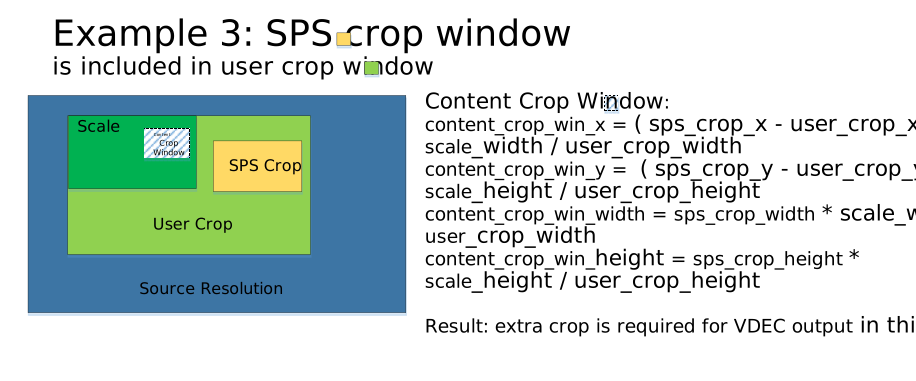
In this case, only the SPS crop window is in the valid display area of the image, so additional cropping of the VDEC output buffer is required. Since the scale function is enabled in this example, the SPS crop window needs to be scaled proportionally to obtain the content crop window.
Note: If the user crop window and the SPS crop window do not intersect, then the entire user crop window is outside the valid display area of the image. This situation should be avoided.
-
-
Capture function
The purpose of capturing images is to keep the output resolution of port0 unchanged while port1 can output images with the original resolution of the bitstream. In this way, when decoding the same code bitstream data frame, two images with different resolutions can be output. In the capture scene, decoding the data frame with the original resolution of the output bitstream can make the captured image clearer. It is important to note that, aside from the following chip: mHera, the remaining chips that support this function only allow original image output for Port1, and Port1 does not support cropping and scaling functions; If users need to adjust the size of Port1 output image, they can bind MI_SCL first to adjust the size of the output image, and then bind MI_VENC to save coded stream. Moreover, this function is only supported when low latency (bDisableLowLatency=FALSE) is enabled.
Note: The chip ifackel does not support this feature.
Port1 Bind scenario:

The following chip: mHera, has extended this function:
-
In addition to supporting Port1, it also supports an additional output from Port2. Port1 and Port2 are time-multiplexed, which means that for one frame of the bitstream, the output from the ports will only occur in the following scenarios: output from Port0 only, output from Port0 combined with output from Port1, or output from Port0 combined with output from Port2. Therefore, the output frame rate from Port1 and Port2 combined must be less than or equal to the output frame rate of Port0. For information on frame rate control settings for the ports, please refer to the MI SYS documentation.
-
Port0, 1, and 2 all support cropping, scaling, and LSYC function (refer to the function descriptions below for LSYC usage limitations). When the scaling feature is enabled, the maximum output resolution for port0 is 3840x2160, and for port1/port2 scaling, it is 1920x1080.
-
-
Refresh frame
Refresh frame means decoding the same frame of bitstream data multiple times, which is used to view the same frame of image after different scaling and cropping operations multiple times. For example, when previewing multiple video images, if you need to display a certain channel in full screen, you can pause the decoding of the channel firstly, then adjust the output scaling and cropping parameters of the channel, and then use this function to re-decode the current bitstream data of the channel, so that the decoded output image resolution can match the screen resolution, thereby achieving a clear full-screen display effect.
Note: 1. When decoding the B frame, this feature is not supported. 2. The chip ifackel does not support this feature.
-
Output image rotation
Rotate the decoded output image, the rotation angle (clockwise) includes: 90°/180°/270°.
Note: Only chip ifackel supports this feature.
-
LSYC function
This function performs lossy compression on the decoded output image and requires the VDEC to be bound with downstream modules that support decompression (currently, only the MI_DISP module supports this). The compressed data is passed to the downstream module via a pipeline, where the decompression hardware decompresses the data to produce an image suitable for display. This function can reduce the usage of the VDEC output buffer while decreasing bandwidth consumption; however, it will result in a loss of image quality. The LSYC function switch is independently configured for each port, with the following limitations: when LSYC is enabled on Port0, it must be disabled on Port1 and Port2; when LSYC is disabled on Port0, Port1 and Port2 can individually enable or disable LSYC.
Note: The chip that supports this function is mHera. There is a restriction on usage: When LSYC is enabled, the maximum output resolution is 4096x4096. The LSYC function does not support H.265 bitstreams that use multi-tile partitioning (when the syntax named tiles_enabled_flag in picture parameter set(PPS) is set to 1). If decoding encounters such a bitstream, the LSYC function will be forcibly disabled.
1.5. modparam
-
vdec supports modifying some parameter configurations through modparam, and users can modify them as needed. The specific information of each parameter is as follows:
Parameter name
Function
Default value
iBopper ifackel jaguar1 mHera cpuMaskAffinity The affinity between VDEC threads and CPUs. Parameter configuration instructions will be explained in the following section. 0 0 0 0 threadPriority VDEC thread priority, valid range [0-99]. If left unconfigured or set outside the valid range, the system will internally apply the default value. 99 99 99 99 maxChnNum The maximum number of channels that can be created on a single VDEC device, with a valid range of [1, N] (where N refers to Table 1‑1 Chip Decoding Specifications). If left unconfigured or set beyond the valid range, the system will internally use the default value. 64 1 64 64 maxChnId The maximum channel number that can be created on a single VDEC channel, with a valid range of [1, N) (where N refers to Table 1‑1 Chip Decoding Specifications). If left unconfigured or set beyond the valid range, the system will internally use the default value. 64 1 64 64 vdec_clock VDEC hardware clock. If not set or set to 0, the default value will be used internally. Note: Chips that support multiple VDEC hardware device (such as mHera) need to be configured in the form of an array, corresponding to the clock settings for the respective number of supported VDEC hardware device. For example, setting it to [504000000, 480000000] indicates that the VDEC hardware clock for Device0 is 504000000, and for Device1 it is 480000000. 0 0 0 [0,0] vdec_clock_2nd VDEC hardware submodule clock. If not set or set to 0, the default value will be used internally. 0 0 0 x vdec_clock_axi VDEC arbiter clock, if not set or set to 0, the default value will be used internally. 0 0 0 x -
The cpuMaskAffinity is represented as a 16-bit mask format, divided into four groups of 4 bits each. From the lowest to the highest bits, each group corresponds to the affinity configuration for VDEC device threads 0–3, respectively. Within each 4-bit group [0,3], each bit indicates whether the corresponding VDEC device thread is bound to CPU cores [0,3]. A bit value of 1 signifies binding to that CPU core, while 0 means no binding. If all 4 bits in a group are 0, the VDEC device thread is not bound to any CPU core, and its scheduling is delegated to the CPU. For example, to bind VDEC device thread 0 to CPU core 1, set cpuMaskAffinity to 2 (binary: 0000 0000 0000 0010).
-
Module parameters are configured and modified through the file modparam.json, which is usually placed in the board's /config directory. Parameter configuration can be referred to as follows:
"E_MI_MODULE_ID_VDEC" : { "cpuMaskAffinity" : 0, "threadPriority" : 99, "maxChnNum" : 64, "maxChnId" : 64, "vdec_clock" : 0, "vdec_clock_2nd" : 0, "vdec_clock_axi" : 0 } -
Module parameters can also be imported into the modified configuration through the echo command. The process is as follows:
-
Create or copy a json file from the /config directory and modify it according to the required format. Taking the parameter vdec_clock as an example, the new file is named vdec_clock.json and the content is as follows:
"E_MI_MODULE_ID_VDEC" : { "cpuMaskAffinity" : 1, "threadPriority" : 98, "maxChnNum" : 32, "maxChnId" : 32, "vdec_clock": 384000000, "vdec_clock_2nd" : 384000000, "vdec_clock_axi" : 384000000 } -
Use echo command to import json configuration
echo vdec_clock.json > /proc/mi_modules/mi_common/modparam -
After reloading mi_vdec.ko, run the application or call VDEC related API
-
-
Note
-
Module parameters take effect when insmod mi_vdec.ko. After the VDEC module is started, the modification command will be invalid.
-
After each system restart, the module parameters will be reset to the default values and the user needs to reconfigure the module parameters.
-
1.6. Application Scenarios
-
Local video playback
Read local video files, decode out the original frames through the video decoding module, and display them on the screen.
-
Network video preview
Read the network video stream, decode out the original frames through the video decoding module and display them on the screen, so as to preview the network video in real time.
-
Video Decoding and Re-encoding
Read video stream data from local files or network, decode out the original frames through the video decoding module, and after further processing by the application, send them to the video encoding module to re-encode them into a video stream.
1.7. Example Introduction
This example calls the MI VDEC API to decode a local H.264 video file with a resolution of 1920x1080, and binds the VDEC and DISP modules to play back at a frame rate of 30fps.
#include <stdio.h>
#include <stdlib.h>     // malloc + free
#include <string.h>     // memset
#include <unistd.h>     // usleep
#include <stdint.h>     // uint8_t

#include "mi_sys.h"     // MI SYS API
#include "mi_vdec.h"    // MI VDEC API
#include "mi_disp.h"    // MI DISP API

static const int SCREEN_WIDTH = 1920;       // width of display screen
static const int SCREEN_HEIGHT = 1080;      // height of display screen
static const int VIDEO_WIDTH = 1920;        // width of input video bitstream file
static const int VIDEO_HEIGHT = 1080;       // height of input video bitstream file
static const int BS_BUFFER_SIZE = 0x100000; // buffer for read from input file

int VdecInit(MI_VDEC_DEV vdecDev, MI_VDEC_CHN vdecChn, MI_VDEC_CodecType_e eCodecType, int width, int height)
{
    MI_S32 s32Ret   = MI_SUCCESS;
    MI_U8  u8PortId = 0;

    // Create vdec device
    MI_VDEC_InitParam_t stInitParam;
    memset(&stInitParam, 0, sizeof(MI_VDEC_InitParam_t));
    stInitParam.u16MaxWidth = 8192;
    stInitParam.u16MaxHeight = 4096;
    if((s32Ret = MI_VDEC_CreateDev(vdecDev, &stInitParam)) != MI_SUCCESS)
    {
        printf("MI_VDEC_CreateDev failed, ret:0x%x\n", s32Ret);
        return -1;
    }

    // Create vdec channel with given information
    MI_VDEC_ChnAttr_t stChnAttr;
    memset(&stChnAttr, 0x0, sizeof(MI_VDEC_ChnAttr_t));
    stChnAttr.eCodecType = eCodecType;
    stChnAttr.u32PicWidth = width;
    stChnAttr.u32PicHeight = height;
    stChnAttr.eVideoMode = E_MI_VDEC_VIDEO_MODE_FRAME;
    stChnAttr.u32BufSize = 2 * 1024 * 1024;
    stChnAttr.eDpbBufMode = E_MI_VDEC_DPB_MODE_NORMAL;
    stChnAttr.stVdecVideoAttr.u32RefFrameNum = 10;
    stChnAttr.u32Priority = 0;
    stChnAttr.stVdecVideoAttr.stErrHandlePolicy.bUseCusPolicy = false;
    stChnAttr.stVdecVideoAttr.bDisableLowLatency = true;
    if ((s32Ret = MI_VDEC_CreateChn(vdecDev, vdecChn, &stChnAttr)) != MI_SUCCESS)
    {
        printf("MI_VDEC_CreateChn failed, ret:0x%x\n", s32Ret);
        return -1;
    }

    // Set scale output size if needed
    // Only support zoom out, DO NOT support zoom in
    MI_VDEC_OutputPortAttr_t stOutputPortAttr;
    memset(&stOutputPortAttr, 0, sizeof(stOutputPortAttr));
    stOutputPortAttr.u16Width = width;
    stOutputPortAttr.u16Height = height;
    if ((s32Ret = MI_VDEC_SetOutputPortAttr(vdecDev, vdecChn, u8PortId, &stOutputPortAttr)) != MI_SUCCESS)
    {
        printf("MI_VDEC_SetOutputPortAttr failed, ret:0x%x\n", s32Ret);
        return -1;
    }

    // Start vdec channel
    if ((s32Ret = MI_VDEC_StartChn(vdecDev, vdecChn)) != MI_SUCCESS)
    {
        printf("MI_VDEC_StartChn failed, ret:0x%x\n", s32Ret);
        return -1;
    }

    return 0;
}

void VdecDeinit(MI_VDEC_DEV vdecDev, MI_VDEC_CHN vdecChn)
{
    // Stop vdec channel
    MI_VDEC_StopChn(vdecDev, vdecChn);
    // Destroy vdec channel
    MI_VDEC_DestroyChn(vdecDev, vdecChn);
    // Destroy vdec device
    MI_VDEC_DestroyDev(vdecDev);
}

int DispInit(MI_DISP_DEV dispDev, MI_DISP_LAYER dispLayer, int srcWidth, int srcHeight)
{
    MI_S32 s32Ret = MI_SUCCESS;

    MI_DISP_PubAttr_t stDispPubAttr;
    memset(&stDispPubAttr, 0, sizeof(stDispPubAttr));
    stDispPubAttr.u32BgColor = 0x800080;    // YUYV Black
    stDispPubAttr.eIntfSync = E_MI_DISP_OUTPUT_1080P60;
    stDispPubAttr.eIntfType = E_MI_DISP_INTF_HDMI;
    if ((s32Ret = MI_DISP_SetPubAttr(dispDev, &stDispPubAttr)) != MI_SUCCESS)
    {
        printf("MI_DISP_SetPubAttr failed, ret:0x%x\n", s32Ret);
        return -1;
    }
    if ((s32Ret = MI_DISP_Enable(dispDev)) != MI_SUCCESS)
    {
        printf("MI_DISP_Enable failed, ret:0x%x\n", s32Ret);
        return -1;
    }

    MI_DISP_VideoLayerAttr_t stLayerAttr;
    memset(&stLayerAttr, 0, sizeof(stLayerAttr));
    stLayerAttr.stVidLayerSize.u16Width  = SCREEN_WIDTH;
    stLayerAttr.stVidLayerSize.u16Height = SCREEN_HEIGHT;
    stLayerAttr.ePixFormat = E_MI_SYS_PIXEL_FRAME_YUV_SEMIPLANAR_420;
    stLayerAttr.stVidLayerDispWin.u16X = 0;
    stLayerAttr.stVidLayerDispWin.u16Y = 0;
    stLayerAttr.stVidLayerDispWin.u16Width = SCREEN_WIDTH;
    stLayerAttr.stVidLayerDispWin.u16Height = SCREEN_HEIGHT;
    if ((s32Ret = MI_DISP_BindVideoLayer(dispLayer, dispDev)) != MI_SUCCESS)
    {
        printf("MI_DISP_BindVideoLayer failed, ret:0x%x\n", s32Ret);
        return -1;
    }
    if ((s32Ret = MI_DISP_SetVideoLayerAttr(dispLayer, &stLayerAttr)) != MI_SUCCESS)
    {
        printf("MI_DISP_SetVideoLayerAttr failed, ret:0x%x\n", s32Ret);
        return -1;
    }
    if ((s32Ret = MI_DISP_EnableVideoLayer(dispLayer)) != MI_SUCCESS)
    {
        printf("MI_DISP_EnableVideoLayer failed, ret:0x%x\n", s32Ret);
        return -1;
    }

    MI_DISP_InputPortAttr_t stInputPortAttr;
    memset(&stInputPortAttr, 0, sizeof(stInputPortAttr));
    // Video frame size
    stInputPortAttr.u16SrcWidth = srcWidth;
    stInputPortAttr.u16SrcHeight = srcHeight;
    stInputPortAttr.stDispWin.u16X = 0;
    stInputPortAttr.stDispWin.u16Y = 0;
    stInputPortAttr.stDispWin.u16Width = SCREEN_WIDTH;
    stInputPortAttr.stDispWin.u16Height = SCREEN_HEIGHT;
    if ((s32Ret = MI_DISP_SetInputPortAttr(dispLayer, 0, &stInputPortAttr)) != MI_SUCCESS)
    {
        printf("MI_DISP_SetInputPortAttr failed, ret:0x%x\n", s32Ret);
        return -1;
    }
    if ((s32Ret = MI_DISP_EnableInputPort(dispLayer, 0)) != MI_SUCCESS)
    {
        printf("MI_DISP_EnableInputPort failed, ret:0x%x\n", s32Ret);
        return -1;
    }

    return 0;
}

void DispDeinit(MI_DISP_DEV dispDev, MI_DISP_LAYER dispLayer)
{
    MI_DISP_DisableInputPort(dispLayer, 0);
    MI_DISP_DisableVideoLayer(dispLayer);
    MI_DISP_UnBindVideoLayer(dispLayer, dispDev);
    MI_DISP_Disable(dispDev);
}

// Find start code {0x00 0x00 0x00 0x01} of H.264
const uint8_t *FindStartcode(const uint8_t *pStart, const uint8_t *pEnd)
{
    const uint8_t *out = NULL;
    const uint8_t *p = pStart;
    const uint8_t *end = pEnd;
    const uint8_t *a = p + 4 - ((intptr_t)p & 3);

    for (end -= 3; p < a && p < end; p++)
    {
        if (p[0] == 0 && p[1] == 0 && p[2] == 1)
        {
            out = p;
            goto EXIT;
        }
    }

    for (end -= 3; p < end; p += 4)
    {
        uint32_t x = *(const uint32_t *)p;
        if ((x - 0x01010101) & (~x) & 0x80808080) // generic
        {
            if (p[1] == 0)
            {
                if (p[0] == 0 && p[2] == 1)
                {
                    out = p;
                    goto EXIT;
                }
                if (p[2] == 0 && p[3] == 1)
                {
                    out = p + 1;
                    goto EXIT;
                }
            }
            if (p[3] == 0)
            {
                if (p[2] == 0 && p[4] == 1)
                {
                    out = p + 2;
                    goto EXIT;
                }
                if (p[4] == 0 && p[5] == 1)
                {
                    out = p + 3;
                    goto EXIT;
                }
            }
        }
    }

    for (end += 3; p < end; p++)
    {
        if (p[0] == 0 && p[1] == 0 && p[2] == 1)
        {
            out = p;
            goto EXIT;
        }
    }

    out = end + 3;

EXIT:
    if (pStart < out && out < pEnd && !out[-1])
        out--;

    return out;
}

int main(int argc, const char *argv[])
{
    const char *pInputFilePath = NULL;
    FILE *pInputFile = NULL;
    uint8_t *pBsBuffer = NULL;
    uint64_t naluCnt = 0;

    MI_VDEC_DEV vdecDev = 0;
    MI_VDEC_CHN vdecChn = 0;
    MI_VDEC_CodecType_e eCodecType = E_MI_VDEC_CODEC_TYPE_H264;
    MI_SYS_ChnPort_t stVdecChnPort, stDispChnPort;
    MI_DISP_DEV dispDev = 0;
    MI_DISP_LAYER dispLayer = 0;
    MI_U32 u32FrameRate = 30;

    for (int i = 1; i < argc; i++)
    {
        if (!strcmp(argv[i], "-i"))
            pInputFilePath = argv[++i];
    }

    if (pInputFilePath)
    {
        printf("InputFilePath:%s\n", pInputFilePath);
        if ((pInputFile = fopen(pInputFilePath, "rb")) == NULL)
        {
            printf("Failed to open input file for read\n");
            goto EXIT;
        }
    }
    else
    {
        printf("No input file specified\n");
        printf("Usage: %s -i INPUT_FILE\n", argv[0]);
        goto EXIT;
    }

    // Init MI SYS
    MI_SYS_Init(0);

    // Init MI VDEC
    if (VdecInit(vdecDev, vdecChn, eCodecType, VIDEO_WIDTH, VIDEO_HEIGHT) < 0)
        goto EXIT;

    // Init MI DISP
    if (DispInit(dispDev, dispLayer, VIDEO_WIDTH, VIDEO_HEIGHT) < 0)
        goto EXIT;

    // Set output port depth(total output buffer count that VDEC can use)
    memset(&stVdecChnPort, 0x0, sizeof(MI_SYS_ChnPort_t));
    stVdecChnPort.eModId = E_MI_MODULE_ID_VDEC;
    stVdecChnPort.u32DevId = vdecDev;
    stVdecChnPort.u32ChnId = vdecChn;
    stVdecChnPort.u32PortId = 0;
    MI_SYS_SetChnOutputPortDepth(0, &stVdecChnPort, 0, 4);

    // Bind vdec and disp
    memset(&stDispChnPort, 0x0, sizeof(MI_SYS_ChnPort_t));
    stDispChnPort.eModId = E_MI_MODULE_ID_DISP;
    stDispChnPort.u32DevId = dispDev;
    stDispChnPort.u32ChnId = 0;
    stDispChnPort.u32PortId = 0;
    MI_SYS_BindChnPort2(0, &stVdecChnPort, &stDispChnPort, u32FrameRate, u32FrameRate, E_MI_SYS_BIND_TYPE_FRAME_BASE, 0);

    // Read nalu from input es file, and send stream to MI VDEC
    pBsBuffer = (uint8_t *)malloc(BS_BUFFER_SIZE);
    long readPosition = 0;
    while (true)
    {
        fseek(pInputFile, readPosition, SEEK_SET);
        memset(pBsBuffer, 0, BS_BUFFER_SIZE);
        size_t readSize = fread(pBsBuffer, 1, BS_BUFFER_SIZE, pInputFile);
        if (readSize == 0)
        {
            printf("Get EOF flag, restart from begining\n");
            readPosition = 0;
            continue;
        }

        const uint8_t *pStart = pBsBuffer;
        const uint8_t *pEnd = pBsBuffer + readSize;
        const uint8_t *pNaluStart = FindStartcode(pStart, pEnd);
        const uint8_t *pNaluEnd = NULL;
        int i = 0;
        // Skip start code
        while (pNaluStart && (pNaluStart < pEnd) && !pNaluStart[i]) i++;
        // Find next nalu start code as nalu end
        pNaluEnd = FindStartcode(pNaluStart + i, pEnd);
        int naluSize = pNaluEnd - pNaluStart;

        printf("Get new nalu pos:%ld size:%d cnt:%lld\n", readPosition, naluSize, ++naluCnt);

        // Mark next nalu read position in file
        readPosition += (pNaluEnd - pStart);

        // Send bitstream data to MI VDEC
        MI_VDEC_VideoStream_t stVdecStream;
        memset(&stVdecStream, 0x0, sizeof(MI_VDEC_VideoStream_t));
        stVdecStream.pu8Addr = (MI_U8 *)pNaluStart;
        stVdecStream.u32Len = naluSize;
        stVdecStream.u64PTS = 0;
        stVdecStream.bEndOfFrame = true;
        stVdecStream.bEndOfStream = 0;
        MI_VDEC_SendStream(vdecDev, vdecChn, &stVdecStream, 0);

        // Sleep for rate control
        usleep(25000);
    }

EXIT:
    DispDeinit(dispDev, dispLayer);
    VdecDeinit(vdecDev, vdecChn);
    // Deinit MI SYS
    MI_SYS_Exit(0);

    if (pInputFile)
        fclose(pInputFile);
    if (pBsBuffer)
        free(pBsBuffer);

    return 0;
}
2. API LIST
This module provides the following APIs:
| API Name | Function |
|---|---|
| MI_VDEC_CreateDev | Create decoding device |
| MI_VDEC_DestroyDev | Destroy decoding device |
| MI_VDEC_CreateChn | Create a decoding channel |
| MI_VDEC_DestroyChn | Destroy a decoding channel |
| MI_VDEC_StartChn | Start the channel decoding |
| MI_VDEC_StopChn | Stop the channel decoding |
| MI_VDEC_GetChnAttr | Get decoding channel attribute |
| MI_VDEC_GetChnStat | Get decoding channel status |
| MI_VDEC_FlushChn | Clear decoding channel cache |
| MI_VDEC_ResetChn | Reset decoding channel |
| MI_VDEC_SetChnParam | Set decoding channel parameter |
| MI_VDEC_GetChnParam | Get decoding channel parameter |
| MI_VDEC_SendStream | Send video stream data to decoding channel |
| MI_VDEC_PauseChn | Pause channel decoding |
| MI_VDEC_RefreshChn | Refresh the channel and re-decode the current frame |
| MI_VDEC_ResumeChn | Resume channel decoding |
| MI_VDEC_StepChn | Channel single frame decoding |
| MI_VDEC_GetUserData | Get decoding channel user data |
| MI_VDEC_ReleaseUserData | Release decoding channel user data |
| MI_VDEC_SetDisplayMode | Set decoding channel display mode |
| MI_VDEC_GetDisplayMode | Get decoding channel display mode |
| MI_VDEC_SetOutputPortAttr | Set decoding channel output port attribute |
| MI_VDEC_GetOutputPortAttr | Get decoding channel output port attribute |
| MI_VDEC_SetOutputPortLayoutMode | Set output port layout mode |
| MI_VDEC_GetOutputPortLayoutMode | Get output port layout mode |
| MI_VDEC_SetDestCrop | Set the decoded image cropping attribute |
| MI_VDEC_GetDestCrop | Get the decoded image cropping attribute |
| MI_VDEC_SetChnErrHandlePolicy | Set the output strategy of the decoded channel error MB data frame |
| MI_VDEC_GetEventFd | Get the device file handle corresponding to the appointed channel |
| MI_VDEC_CloseEventFd | Close the handle of appointed channel |
| MI_VDEC_SubscribeEvent | Start listening to appointed event information of channel |
| MI_VDEC_UnSubscribeEvent | Cancel listening to appointed event information of channel |
| MI_VDEC_GetEvents | Get all event information which generates by the channel |
| MI_VDEC_GetEventData | Get the detailed information of channel appointed event |
| MI_VDEC_ClearEvents | Clear the appointed event information which generates by the channel |
| MI_VDEC_SetChnRotate | Set the output image rotation angle of the decoding channel |
2.1. MI_VDEC_CreateDev
-
Function
Create decoding device.
-
Syntax
MI_S32 MI_VDEC_CreateDev(MI_VDEC_DEV VdecDev, MI_VDEC_InitParam_t *pstInitParam); -
Parameter
Parameter Name Description Input/Output VdecDev Decoding device number. Range: [0, MI_VDEC_MAX_DEV_NUM). Input pstInitParam Decoding initialization parameters pointer. Data type: MI_VDEC_InitParam_t Input -
Return Value
-
MI_SUCCESS: Successful.
-
Not MI_SUCCESS: Failed, see ERROR CODE for details.
-
-
Requirement
-
Header: mi_vdec.h, mi_vdec_datatype.h
-
Library: libmi_vdec.a/libmi_vdec.so
-
-
Note
-
The device number cannot exceed the maximum range.
-
This interface is optional. If it is not called before creating a decoding channel, the decoding device will be created when the decoding channel is created.
-
-
Example
MI_S32 StartVdec(void)
{
    MI_S32 s32Ret = MI_ERR_VDEC_FAILED;
    MI_VDEC_DEV VdecDev = 0;
    MI_VDEC_CHN VdecChn = 0;
    MI_VDEC_InitParam_t stInitParam;
    MI_VDEC_ChnAttr_t stChnAttr;

    memset(&stInitParam, 0x0, sizeof(MI_VDEC_InitParam_t));
    memset(&stChnAttr, 0x0, sizeof(MI_VDEC_ChnAttr_t));

    s32Ret = MI_VDEC_CreateDev(VdecDev, &stInitParam);
    if(MI_SUCCESS != s32Ret)
    {
        printf("MI_VDEC_CreateDev failed, s32Ret: 0x%x.\n", s32Ret);
        return s32Ret;
    }

    VdecChn = 0;
    stChnAttr.eCodecType    = E_MI_VDEC_CODEC_TYPE_H264;
    stChnAttr.u32PicWidth   = 1920;
    stChnAttr.u32PicHeight  = 1080;
    stChnAttr.eVideoMode    = E_MI_VDEC_VIDEO_MODE_FRAME;
    stChnAttr.u32BufSize    = 1024*1024;
    stChnAttr.eDpbBufMode   = E_MI_VDEC_DPB_MODE_INPLACE_ONE_BUF;
    stChnAttr.stVdecVideoAttr.u32RefFrameNum = 1;
    stChnAttr.u32Priority = 0;
    stChnAttr.stVdecVideoAttr.stErrHandlePolicy.bUseCusPolicy = FALSE;
    stChnAttr.stVdecVideoAttr.bDisableLowLatency = FALSE;

    s32Ret = MI_VDEC_CreateChn(VdecDev, VdecChn, &stChnAttr);
    if(MI_SUCCESS != s32Ret)
    {
        printf("MI_VDEC_CreateChn failed, s32Ret: 0x%x.\n", s32Ret);
        return s32Ret;
    }

    return MI_SUCCESS;
}
2.2. MI_VDEC_DestroyDev
-
Function
Destroy decoding device.
-
Syntax
MI_S32 MI_VDEC_DestroyDev(MI_VDEC_DEV VdecDev); -
Parameter
Parameter Name Description Input/Output VdecDev Decoding device number. Range: [0, MI_VDEC_MAX_DEV_NUM). Input -
Return Value
-
MI_SUCCESS: Successful.
-
Not MI_SUCCESS: Failed, see ERROR CODE for details.
-
-
Requirement
-
Header: mi_vdec.h, mi_vdec_datatype.h
-
Library: libmi_vdec.a/libmi_vdec.so
-
-
Note
-
The device number cannot exceed the maximum range.
-
The calling of this interface must be consistent with MI_VDEC_CreateDev. If you choose to call this interface, you have to call it after destroying all the decoding channels; otherwise, the interface will destroy all the decoding channels automatically.
-
If the decoding device has been destroyed and the interface is called again, the error code MI_ERR_VDEC_NOT_INIT will be returned.
-
-
Example
MI_S32 StopVdec(void)
{
    MI_S32 s32Ret = MI_ERR_VDEC_FAILED;
    MI_VDEC_DEV VdecDev = 0;
    MI_VDEC_CHN VdecChn = 0;

    s32Ret = MI_VDEC_DestroyChn(VdecDev, VdecChn);
    if(MI_SUCCESS != s32Ret)
    {
        printf("MI_VDEC_DestroyChn failed, s32Ret: 0x%x.\n", s32Ret);
        return s32Ret;
    }

    //Confirm that you have destroyed all channels
    s32Ret = MI_VDEC_DestroyDev(VdecDev);
    if(MI_SUCCESS != s32Ret)
    {
        printf("MI_VDEC_DestroyDev failed, s32Ret: 0x%x.\n", s32Ret);
        return s32Ret;
    }

    return MI_SUCCESS;
}
2.3. MI_VDEC_CreateChn
-
Function
Create a video decoding channel
-
Syntax
MI_S32 MI_VDEC_CreateChn(MI_VDEC_DEV VdecDev, MI_VDEC_CHN VdecChn, MI_VDEC_ChnAttr_t *pstChnAttr); -
Parameter
Parameter Name Description Input/Output VdecDev Decoding device number. Range: [0, MI_VDEC_MAX_DEV_NUM). Input VdecChn Decoding channel number Range: [0, MI_VDEC_MAX_CHN_ID) Input pstChnAttr Decoding channel attribute pointer Data type: MI_VDEC_ChnAttr_t Input -
Return Value
-
MI_SUCCESS: Successful.
-
Not MI_SUCCESS: Failed, see ERROR CODE for details.
-
-
Requirement
-
Header: mi_vdec.h, mi_vdec_datatype.h
-
Library: libmi_vdec.a/libmi_vdec.so
-
-
Note
-
The channel number cannot exceed the maximum channel range allowed.
-
Before creating a decoding channel, you need to ensure that the decoding channel has not been created or destroyed, otherwise the error code MI_ERR_VDEC_CHN_EXIST will be returned.
-
If eDpbBufMode is set to E_MI_VDEC_DPB_MODE_INPLACE_ONE_BUF or E_MI_VDEC_DPB_MODE_INPLACE_TWO_BUF, we only guarantee that the decoder can decode the bitstream encoded by SGS encoder well, but the third party’s decode bitstream is not guaranteed to be fully supported. Additionally, the vertical component of the motion vectors (MV) in the bitstream must not exceed 256. In addition, eDpbBufMode should be consistent with reference frame number of the bitstream.
-
For CHIP: ifackel, setting eDpbBufMode is not supported.
-
For CHIP: mHera, decoding of H265 bitstreams with multi-tile partitioning enabled (tiles_enabled_flag set to 1 in the PPS syntax) is not supported when eDpbBufMode is set to either E_MI_VDEC_DPB_MODE_INPLACE_ONE_BUF or E_MI_VDEC_DPB_MODE_INPLACE_TWO_BUF.
-
If you need to decode the B-frame bitstream, you need to set bDisableLowLatency to TRUE to ensure that the decoder outputs the decoded images in the display order; otherwise, the output images will have jitter and inconsistency problems. Note: The chip ifackel does not support to set bDisableLowLatency to TRUE.
-
-
Example
MI_S32 StartVdec(void)
{
    MI_S32 s32Ret = MI_ERR_VDEC_FAILED;
    MI_VDEC_DEV VdecDev = 0;
    MI_VDEC_CHN VdecChn = 0;
    MI_U8 u8PortId = 0;
    MI_VDEC_DisplayMode_e eDisplayMode = E_MI_VDEC_DISPLAY_MODE_MAX;
    MI_VDEC_ChnAttr_t stChnAttr;
    MI_VDEC_OutputPortAttr_t stOutputPortAttr;
    MI_VDEC_ChnParam_t  stVdecChnParam;

    memset(&stChnAttr, 0x0, sizeof(MI_VDEC_ChnAttr_t));
    memset(&stOutputPortAttr, 0x0, sizeof(MI_VDEC_OutputPortAttr_t));
    memset(&stVdecChnParam, 0x0, sizeof(MI_VDEC_ChnParam_t));

    VdecChn = 0;
    stChnAttr.eCodecType    = E_MI_VDEC_CODEC_TYPE_H264;
    stChnAttr.u32PicWidth   = 1920;
    stChnAttr.u32PicHeight  = 1080;
    stChnAttr.eVideoMode    = E_MI_VDEC_VIDEO_MODE_FRAME;
    stChnAttr.u32BufSize    = 1024*1024;
    stChnAttr.eDpbBufMode   = E_MI_VDEC_DPB_MODE_INPLACE_ONE_BUF;
    stChnAttr.stVdecVideoAttr.u32RefFrameNum = 1;
    stChnAttr.u32Priority = 0;
    stChnAttr.stVdecVideoAttr.stErrHandlePolicy.bUseCusPolicy = FALSE;
    stChnAttr.stVdecVideoAttr.bDisableLowLatency = FALSE;

    s32Ret = MI_VDEC_CreateChn(VdecDev, VdecChn, &stChnAttr);
    if(MI_SUCCESS != s32Ret)
    {
        printf("MI_VDEC_CreateChn failed, s32Ret: 0x%x.\n", s32Ret);
        return s32Ret;
    }

    eDisplayMode = E_MI_VDEC_DISPLAY_MODE_PLAYBACK;
    s32Ret = MI_VDEC_SetDisplayMode (VdecDev, VdecChn, eDisplayMode);
    if(MI_SUCCESS != s32Ret)
    {
        printf("MI_VDEC_SetDisplayMode failed, s32Ret: 0x%x.\n", s32Ret);
        return s32Ret;
    }

    s32Ret = MI_VDEC_StartChn(VdecDev, VdecChn);
    if(MI_SUCCESS != s32Ret)
    {
        printf("MI_VDEC_StartChn failed, s32Ret: 0x%x.\n", s32Ret);
        return s32Ret;
    }

    stOutputPortAttr.u16Width = 640;
    stOutputPortAttr.u16Height = 480;
    s32Ret = MI_VDEC_SetOutputPortAttr(VdecDev, VdecChn, u8PortId, &stOutputPortAttr);
    if(MI_SUCCESS != s32Ret)
    {
        printf("MI_VDEC_SetOutputPortAttr failed, s32Ret: 0x%x.\n", s32Ret);
        return s32Ret;
    }

    stCropCfg.bEnable   = TRUE;
    stCropCfg.stRect.u16X  = 0;
    stCropCfg.stRect.u16Y  = 0;
    stCropCfg.stRect.u16Width = 720;
    stCropCfg.stRect.u16Height = 576;
    s32Ret = MI_VDEC_SetDestCrop(VdecDev, VdecChn, u8PortId, &stCropCfg);
    if(MI_SUCCESS != s32Ret)
    {
        printf("MI_VDEC_SetDestCrop failed, s32Ret: 0x%x.\n", s32Ret);
        return s32Ret;
    }

    stVdecChnParam.eDecMode = E_MI_VDEC_DECODE_MODE_I;
    s32Ret = MI_VDEC_SetChnParam(VdecDev, VdecChn, &stVdecChnParam);
    if(MI_SUCCESS != s32Ret)
    {
        printf("MI_VDEC_SetChnParam failed, s32Ret: 0x%x.\n", s32Ret);
        return s32Ret;
    }

    return MI_SUCCESS;
}
2.4. MI_VDEC_DestroyChn
-
Function
Destroy a video decoding channel.
-
Syntax
MI_S32 MI_VDEC_DestroyChn(MI_VDEC_DEV VdecDev, MI_VDEC_CHN VdecChn); -
Parameter
Parameter Name Description Input/Output VdecDev Decoding device number. Range: [0, MI_VDEC_MAX_DEV_NUM). Input VdecChn Video decoding channel number. Range: [0, MI_VDEC_MAX_CHN_ID). Input -
Return Value
-
MI_SUCCESS: Successful.
-
Not MI_SUCCESS: Failed, see ERROR CODE for details.
-
-
Requirement
-
Header: mi_vdec.h, mi_vdec_datatype.h
-
Library: libmi_vdec.a/libmi_vdec.so
-
-
Note
-
Before destroying the decoding channel, you must ensure that the channel has been created, otherwise the error code MI_ERR_VDEC_CHN_UNEXIST will be returned.
-
Before destroying the decoding channel, decoding should be stopped first, otherwise the error code MI_ERR_VDEC_CHN_NOT_STOP will be returned.
-
-
Example
MI_S32 StopVdec(void)
{
    MI_S32 s32Ret = MI_ERR_VDEC_FAILED;
    MI_VDEC_DEV VdecDev = 0;
    MI_VDEC_CHN VdecChn = 0;

    // Destroy send stream thread
    ...

    s32Ret = MI_VDEC_StopChn(VdecDev, VdecChn);
    if(MI_SUCCESS != s32Ret)
    {
        printf("MI_VDEC_StopChn failed, s32Ret: 0x%x.\n", s32Ret);
        return s32Ret;
    }

    s32Ret = MI_VDEC_DestroyChn(VdecDev, VdecChn);
    if(MI_SUCCESS != s32Ret)
    {
        printf("MI_VDEC_DestroyChn failed, s32Ret: 0x%x.\n", s32Ret);
        return s32Ret;
    }

    return MI_SUCCESS;
}
2.5. MI_VDEC_StartChn
-
Function
Start the channel decoding.
-
Syntax
MI_S32 MI_VDEC_StartChn(MI_VDEC_DEV VdecDev, MI_VDEC_CHN VdecChn); -
Parameter
Parameter Name Description Input/Output VdecDev Decoding device number. Range: [0, MI_VDEC_MAX_DEV_NUM). Input VdecChn Video decoding channel number. Range: [0, MI_VDEC_MAX_CHN_ID). Input -
Return Value
-
MI_SUCCESS: Successful.
-
Not MI_SUCCESS: Failed, see ERROR CODE for details.
-
-
Requirement
-
Header: mi_vdec.h, mi_vdec_datatype.h
-
Library: libmi_vdec.a/libmi_vdec.so
-
-
Note
-
Before the channel starts decoding, be sure the channel has been created; otherwise, the error code MI_ERR_VDEC_CHN_UNEXIST will be returned.
-
After the channel starts decoding, MI_VDEC_SendStream will be called to send stream successfully.
-
Repeated calling of the interface will return MI_ERR_VDEC_CHN_NOT_STOP.
-
-
Example
See the example of MI_VDEC_CreateChn.
2.6. MI_VDEC_StopChn
-
Function
Stop the channel decoding.
-
Syntax
MI_S32 MI_VDEC_StopChn(MI_VDEC_DEV VdecDev, MI_VDEC_CHN VdecChn); -
Parameter
Parameter Name Description Input/Output VdecDev Decoding device number. Range: [0, MI_VDEC_MAX_DEV_NUM). Input VdecChn Video decoding channel number. Range: [0, MI_VDEC_MAX_CHN_ID). Input -
Return Value
-
MI_SUCCESS: Successful.
-
Not MI_SUCCESS: Failed, see ERROR CODE for details.
-
-
Requirement
-
Header: mi_vdec.h, mi_vdec_datatype.h
-
Library: libmi_vdec.a/libmi_vdec.so
-
-
Note
-
Before calling this interface, be sure the channel has been created; otherwise, the error code MI_ERR_VDEC_CHN_UNEXIST will be returned.
-
Before calling this interface, be sure the channel has been enable; otherwise, the error code MI_ERR_VDEC_CHN_NOT_START will be returned.
-
Calling the video stream sending interface MI_VDEC_SendStream after calling this function will return failed.
-
Repeated calling of this interface will return the error code MI_ERR_VDEC_CHN_NOT_START.
-
When decoding B frames, if the MI_DISP module is bound to the back stage of MI_VDEC, please exit the MI_DISP module before MI_VDEC stops the channel; otherwise, the linear buffer will be released directly when MI_VDEC exits, but MI_DISP is still accessing the output buffer of MI_VDEC at this time, which will cause some Memory problem; if there is a buffer that has not been returned when MI_VDEC exits, the error code MI_ERR_VDEC_BUSY will be reported.
-
-
Example
See the example of MI_VDEC_DestroyChn.
2.7. MI_VDEC_GetChnAttr
-
Function
Get video decoding channel attribute.
-
Syntax
MI_S32 MI_VDEC_GetChnAttr(MI_VDEC_DEV VdecDev, MI_VDEC_CHN VdecChn, MI_VDEC_ChnAttr_t *pstChnAttr); -
Parameter
Parameter Name Description Input/Output VdecDev Decoding device number. Range: [0, MI_VDEC_MAX_DEV_NUM). Input VdecChn Video decoding channel number. Range: [0, MI_VDEC_MAX_CHN_ID). Input pstChnAttr Decoding channel attribute pointer. Data type: MI_VDEC_ChnAttr_t. Output -
Return Value
-
MI_SUCCESS: Successful.
-
Not MI_SUCCESS: Failed, see ERROR CODE for details.
-
-
Requirement
-
Header: mi_vdec.h, mi_vdec_datatype.h
-
Library: libmi_vdec.a/libmi_vdec.so
-
-
Note
- Before getting channel attribute, be sure the channel has been created, otherwise the error code MI_ERR_VDEC_CHN_UNEXIST will be returned.
2.8. MI_VDEC_GetChnStat
-
Function
Get the decoding channel status.
-
Syntax
MI_S32 MI_VDEC_GetChnStat(MI_VDEC_DEV VdecDev, MI_VDEC_CHN VdecChn, MI_VDEC_ChnStat_t *pstChnStat); -
Parameter
Parameter Name Description Input/Output VdecDev Decoding device number. Range: [0, MI_VDEC_MAX_DEV_NUM). Input VdecChn Decoding channel number. Range: [0, MI_VDEC_MAX_CHN_ID). Input pstChnStat Decoding channel status structure pointer. Output -
Return Value
-
MI_SUCCESS: Successful.
-
Not MI_SUCCESS: Failed, see ERROR CODE for details.
-
-
Requirement
-
Header: mi_vdec.h, mi_vdec_datatype.h
-
Library: libmi_vdec.a/libmi_vdec.so
-
-
Note
- Before getting channel status, be sure the channel has been created, otherwise the error code MI_ERR_VDEC_CHN_UNEXIST will be return.
-
Example
See the example of MI_VDEC_SendStream.
2.9. MI_VDEC_FlushChn
-
Function
Clear decoding channel cache.
-
Syntax
MI_S32 MI_VDEC_FlushChn(MI_VDEC_DEV VdecDev, MI_VDEC_CHN VdecChn); -
Parameter
Parameter Name Description Input/Output VdecDev Decoding device number. Range: [0, MI_VDEC_MAX_DEV_NUM). Input VdecChn Video decoding channel number. Range: [0, MI_VDEC_MAX_CHN_ID). Input -
Return Value
-
MI_SUCCESS: Successful.
-
Not MI_SUCCESS: Failed, see ERROR CODE for details.
-
-
Requirement
-
Header: mi_vdec.h, mi_vdec_datatype.h
-
Library: libmi_vdec.a/libmi_vdec.so
-
-
Note
- This interface can be used to clear the cached data of decoding channel when switching to other GOP during decoding, so that decoding can continue.
2.10. MI_VDEC_ResetChn
-
Function
Reset a decoding channel.
-
Syntax
MI_S32 MI_VDEC_ResetChn(MI_VDEC_DEV VdecDev, MI_VDEC_CHN VdecChn); -
Parameter
Parameter Name Description Input/Output VdecDev Decoding device number. Range: [0, MI_VDEC_MAX_DEV_NUM). Input VdecChn Video decoding channel number. Range: [0, MI_VDEC_MAX_CHN_ID). Input -
Return Value
-
MI_SUCCESS: Successful.
-
Not MI_SUCCESS: Failed, see ERROR CODE for details.
-
-
Requirement
-
Header: mi_vdec.h, mi_vdec_datatype.h
-
Library: libmi_vdec.a/libmi_vdec.so
-
-
Note
- This interface is currently not supported.
2.11. MI_VDEC_SetChnParam
-
Function
Set decoding channel parameter.
-
Syntax
MI_S32 MI_VDEC_SetChnParam(MI_VDEC_DEV VdecDev, MI_VDEC_CHN VdecChn, MI_VDEC_ChnParam_t *pstChnParam); -
Parameter
Parameter Name Description Input/Output VdecDev Decoding device number. Range: [0, MI_VDEC_MAX_DEV_NUM). Input VdecChn Video decoding channel number. Range: [0, MI_VDEC_MAX_CHN_ID). Input pstChnParam Channel parameter. Input -
Return Value
-
MI_SUCCESS: Successful.
-
Not MI_SUCCESS: Failed, see ERROR CODE for details.
-
-
Requirement
-
Header: mi_vdec.h, mi_vdec_datatype.h
-
Library: libmi_vdec.a/libmi_vdec.so
-
-
Note
-
Before getting channel attribute, be sure the channel has been created, otherwise the error code MI_ERR_VDEC_CHN_UNEXIST will be return.
-
The channel parameters only support setting the member eDecMode of the structure MI_VDEC_ChnParam_t. Other member settings are invalid.
-
-
Example
See the example of MI_VDEC_CreateChn.
2.12. MI_VDEC_GetChnParam
-
Function
Get decoding channel parameter.
-
Syntax
MI_S32 MI_VDEC_GetChnParam(MI_VDEC_DEV VdecDev, MI_VDEC_CHN VdecChn, MI_VDEC_ChnParam_t *pstChnParam); -
Parameter
Parameter Name Description Input/Output VdecDev Decoding device number. Range: [0, MI_VDEC_MAX_DEV_NUM). Input VdecChn Video decoding channel number. Range: [0, MI_VDEC_MAX_CHN_ID). Input pstChnParam Channel parameter. Output -
Return Value
-
MI_SUCCESS: Successful.
-
Not MI_SUCCESS: Failed, see ERROR CODE for details.
-
-
Requirement
-
Header: mi_vdec.h, mi_vdec_datatype.h
-
Library: libmi_vdec.a/libmi_vdec.so
-
-
Note
- This interface is currently not supported.
2.13. MI_VDEC_SendStream
-
Function
Send video stream data to decoding channel.
-
Syntax
MI_S32 MI_VDEC_SendStream(MI_VDEC_DEV VdecDev, MI_VDEC_CHN VdecChn, MI_VDEC_VideoStream_t *pstVideoStream, MI_S32 s32MilliSec); -
Parameter
Parameter Name Description Input/Output VdecDev Decoding device number. Range: [0, MI_VDEC_MAX_DEV_NUM). Input VdecChn Video decoding channel number. Range: [0, MI_VDEC_MAX_CHN_ID). Input pstVideoStream Decoding video stream data pointer. Please refer to the definition given in MI_VDEC_VideoStream_t. Input s32MilliSec Set data push timeout time parameter. Range: -1: Blocked. 0: Not blocked. Positive values: Timeout time, unit is ms. Input -
Return Value
-
MI_SUCCESS: Successful.
-
Not MI_SUCCESS: Failed, see ERROR CODE for details.
-
-
Requirement
-
Header: mi_vdec.h, mi_vdec_datatype.h
-
Library: libmi_vdec.a/libmi_vdec.so
-
-
Note
-
Stream-based data transmissions is currently not supported.
-
For frame-based case, an entire data frame should be transmitted for each transmission at a time.
-
If the user sets pstVideoStream->u64PTS = -2 when sending the stream, VDEC will discard the frame after decoding. It can be set as required.
-
-
Example
An entire data frame must be sent for each transmission in frame-based transmission. If the current data frame failed during the transmission, re-transmission is required.
MI_S32 VdecSendStream(void)
{
    MI_S32 s32Ret = MI_ERR_VDEC_FAILED;
    MI_VDEC_DEV VdecDev = 0;
    MI_VDEC_CHN VdecChn = 0;
    MI_S32 s32MilliSec = 0;
    MI_VDEC_VideoStream_t stVideoStream;
    MI_VDEC_ChnAttr_t stChnAttr;
    MI_VDEC_ChnStat_t stChnStat;

    do{
        //Check if you need stop sending stream
        if(bStop)
        {
            break;
        }

        memset(&stChnAttr, 0x0, sizeof(MI_VDEC_ChnAttr_t));
        s32Ret = MI_VDEC_GetChnAttr(VdecDev, VdecChn, &stChnAttr);
        if(MI_SUCCESS != s32Ret)
        {
            printf("MI_VDEC_GetChnAttr failed, s32Ret: 0x%x.\n", s32Ret);
            return s32Ret;
        }

        memset(&stChnStat, 0x0, sizeof(MI_VDEC_ChnStat_t));
        s32Ret = MI_VDEC_GetChnStat(VdecDev, VdecChn, &stChnStat);
        if(MI_SUCCESS != s32Ret)
        {
            printf("MI_VDEC_GetChnStat failed, s32Ret: 0x%x.\n", s32Ret);
            return s32Ret;
        }

        //suggest to check chn status
        if(stChnAttr.u32Bufsize - stChnStat.u32LeftStreamBytes < u32StreamSize)
        {
            continue;
        }

        memset(&stVideoStream, 0x0, sizeof(MI_VDEC_VideoStream_t));
        stVideoStream.pu8Addr = pu8StreamBuf;
        stVideoStream.u32Len  = u32StreamSize;
        stVideoStream.u64PTS  = u64StreamPts;
        stVideoStream.bEndOfFrame  = TRUE;
        stVideoStream.bEndOfStream = FALSE;
        s32MilliSec = 0;                    //0ms
        s32Ret = MI_VDEC_SendStream(VdecDev, VdecChn, &stVideoStream, s32MilliSec);
        if(MI_SUCCESS != s32Ret)
        {
            printf("MI_VDEC_SendStream failed, s32Ret: 0x%x.\n", s32Ret);
            continue;
        }
    }while(!ShouldStop);

    return MI_SUCCESS;
}
2.14. MI_VDEC_PauseChn
-
Function
Pause channel decoding.
-
Syntax
MI_S32 MI_VDEC_PauseChn(MI_VDEC_DEV VdecDev, MI_VDEC_CHN VdecChn); -
Parameter
Parameter Name Description Input/Output VdecDev Decoding device number. Range: [0, MI_VDEC_MAX_DEV_NUM). Input VdecChn Video decoding channel number. Range: [0, MI_VDEC_MAX_CHN_ID). Input -
Return Value
-
MI_SUCCESS: Successful.
-
Not MI_SUCCESS: Failed, see ERROR CODE for details.
-
-
Requirement
-
Header: mi_vdec.h, mi_vdec_datatype.h
-
Library: libmi_vdec.a/libmi_vdec.so
-
-
Note
-
After calling this interface, the decoder pauses decoding; at this time, the upper layer can continue to call the MI_VDEC_SendStream interface to send streams, but when the stream buffer is full, MI_VDEC_SendStream will return MI_ERR_VDEC_BUF_FULL.
-
This interface can be called repeatedly without error.
-
The chip ifackel does not support this interface.
-
-
Example
MI_S32 PauseChn(void)
{
    MI_S32 s32Ret = MI_ERR_VDEC_FAILED;
    MI_VDEC_DEV VdecDev  = 0;
    MI_VDEC_CHN VdecChn  = 0;
    MI_U32 u32RefreshCnt = 0;

    //While decoding...

    s32Ret = MI_VDEC_PauseChn(VdecDev, VdecChn);
    if (MI_SUCCESS != s32Ret)
    {
        printf("MI_VDEC_PauseChn failed, s32Ret: 0x%x.\n", s32Ret);
        return s32Ret;
    }

    //refresh 10 times
    while (u32RefreshCnt < 10)
    {
        s32Ret = MI_VDEC_RefreshChn(VdecDev, VdecChn);
        if(MI_SUCCESS != s32Ret)
        {
            printf("MI_VDEC_RefreshChn failed, s32Ret: 0x%x.\n", s32Ret);
            break;
        }
        u32RefreshCnt ++;
        usleep(100*1000);
    }

    s32Ret = MI_VDEC_ResumeChn(VdecDev, VdecChn);
    if (MI_SUCCESS != s32Ret)
    {
        printf("MI_VDEC_ResumeChn failed, s32Ret: 0x%x.\n", s32Ret);
        return s32Ret;
    }
    return MI_SUCCESS;
}
2.15. MI_VDEC_RefreshChn
-
Function
Refresh the channel and re-decode the current frame.
-
Syntax
MI_S32 MI_VDEC_RefreshChn(MI_VDEC_DEV VdecDev, MI_VDEC_CHN VdecChn); -
Parameter
Parameter Name Description Input/Output VdecDev Decoding device number. Range: [0, MI_VDEC_MAX_DEV_NUM). Input VdecChn Video decoding channel number. Range: [0, MI_VDEC_MAX_CHN_ID). Input -
Return Value
-
MI_SUCCESS: Successful.
-
Not MI_SUCCESS: Failed, see ERROR CODE for details.
-
-
Requirement
-
Header: mi_vdec.h, mi_vdec_datatype.h
-
Library: libmi_vdec.a/libmi_vdec.so
-
-
Note
-
When calling this interface, please ensure that MI_VDEC_PauseChn has been called to stop decoding, otherwise it will return MI_ERR_VDEC_NOT_DISABLE.
-
Every time this interface is called, it will trigger the decoder to re-decode the current frame; it can be called more than once, and the zoom factor can be adjusted with MI_VDEC_SetOutputPortAttr to adapt to different scene requirements.
-
When calling this interface, please ensure that there is still data to be decoded in the video stream buffer, otherwise refresh cannot be completed.
-
When the user calls the interface continuously, if the last refresh or step task is not completed, the interface will return MI_ERR_VDEC_BUSY.
-
When decoding the B frame, this function is not supported.
-
The chip ifackel does not support this interface.
-
-
Example
Refer the example of MI_VDEC_PauseChn and MI_VDEC_StepChn.
MI_VDEC supports digital zoom and picture capture during pause.
Example: Suppose that the output resolution of MI_DISP in preview mode is 1920x1080, and the 4 channels are all 1080P source streams while decoding and previewing, the output resolution of each channel is set to 960x540 for output display. If you pause the decoding and switch channel 2 to full-screen preview, it will be displayed in full-screen 1920x1080, and the image data will be distorted. By calling MI_VDEC_RefreshChn, the 1920x1080 image of the current pause data frame can be displayed without distortion.

The channel relies on the combination of MI_VDEC_PauseChn, MI_VDEC_RefreshChn, MI_VDEC_ResumeChn and MI_VDEC_SendStream to realize the pause electronic zoom function, so that images with different resolutions can be obtained for the same bitstream data frame. As follows, image 3 needs to be output 4 times repeatedly.
Calling sequence of API combination:
-
Call MI_VDEC_SendStream to send the video stream data of data frame ‘1’ and ‘2’.
-
Call MI_VDEC_PauseChn to pause the decoder and enter the decoded output repeat image frame mode.
-
Call MI_VDEC_SendStream to send the video stream data that needs to repeatedly output image "3" to the decoder.
-
Repeatedly call MI_VDEC_RefreshChn to output image ‘3’, and output 1 frame of image for each call. The number of calls is unlimited. The current example is called 4 times.
-
Call MI_VDEC_ResumeChn to exit the repeated decoding same image frame mode.
-
Call MI_VDEC_SendStream to send the video stream data of data frame ‘4’ and ‘5’.

-
2.16. MI_VDEC_ResumeChn
-
Function
Resume channel decoding.
-
Syntax
MI_S32 MI_VDEC_ResumeChn(MI_VDEC_DEV VdecDev, MI_VDEC_CHN VdecChn); -
Parameter
Parameter Name Description Input/Output VdecDev Decoding device number. Range: [0, MI_VDEC_MAX_DEV_NUM). Input VdecChn Video decoding channel number. Range: [0, MI_VDEC_MAX_CHN_ID). Input -
Return Value
-
MI_SUCCESS: Successful.
-
Not MI_SUCCESS: Failed, see ERROR CODE for details.
-
-
Requirement
-
Header: mi_vdec.h, mi_vdec_datatype.h
-
Library: libmi_vdec.a/libmi_vdec.so
-
-
Note
-
Before calling this interface, be sure the channel has been created; otherwise, the error code MI_ERR_VDEC_CHN_UNEXIST will be returned.
-
Before calling this interface, be sure the channel has been enable; otherwise, the error code MI_ERR_VDEC_CHN_NOT_START will be returned.
-
It is allowed to call this interface repeatedly.
-
If the last refresh or step task is not completed when calling this interface, the interface will return MI_ERR_VDEC_BUSY.
-
The chip ifackel does not support this interface.
-
-
Example
Refer the example of MI_VDEC_PauseChn and MI_VDEC_StepChn.
2.17. MI_VDEC_StepChn
-
Function
Channel single frame decoding.
-
Syntax
MI_S32 MI_VDEC_StepChn(MI_VDEC_DEV VdecDev, MI_VDEC_CHN VdecChn); -
Parameter
Parameter Name Description Input/Output VdecDev Decoding device number. Range: [0, MI_VDEC_MAX_DEV_NUM). Input VdecChn Video decoding channel number. Range: [0, MI_VDEC_MAX_CHN_ID). Input -
Return Value
-
MI_SUCCESS: Successful.
-
Not MI_SUCCESS: Failed, see ERROR CODE for details.
-
-
Requirement
-
Header: mi_vdec.h, mi_vdec_datatype.h
-
Library: libmi_vdec.a/libmi_vdec.so
-
-
Note
-
Each time this interface is called, it will trigger the decoder to decode the next frame; it can be called multiple times, and the zoom factor can be adjusted with MI_VDEC_SetOutputPortAttr to suit different scene requirements.
-
When calling this interface, the user needs to ensure that there is still data to be decoded in the video stream buffer, otherwise the step cannot be completed.
-
When the user calls the interface multiple times, if the last refresh or step task is not completed, the error code MI_ERR_VDEC_BUSY will be returned.
-
The chip ifackel does not support this interface.
-
-
Example
Case 1:
MI_S32 StepChn(void)
{
    MI_S32 s32Ret = MI_ERR_VDEC_FAILED;
    MI_VDEC_DEV VdecDev  = 0;
    MI_VDEC_CHN VdecChn  = 0;

    //While decoding...

    s32Ret = MI_VDEC_PauseChn(VdecDev, VdecChn);
    if (MI_SUCCESS != s32Ret)
    {
        printf("MI_VDEC_PauseChn failed, s32Ret: 0x%x.\n", s32Ret);
        return s32Ret;
    }

    /// It can be replaced by another independent thread calling MI_VDEC_SendStream.
    s32Ret = MI_VDEC_SendStream(VdecDev, VdecChn, &stVdecStream, 0);
    if(MI_SUCCESS != s32Ret)
    {
        printf("MI_VDEC_ SendStream failed, s32Ret: 0x%x.\n", s32Ret);
        return s32Ret;
    }

    s32Ret = MI_VDEC_StepChn(VdecDev, VdecChn);
    if(MI_SUCCESS != s32Ret)
    {
        printf("MI_VDEC_StepChn failed, s32Ret: 0x%x.\n", s32Ret);
        return s32Ret;
    }
    usleep(20*1000);

    s32Ret = MI_VDEC_ResumeChn(VdecDev, VdecChn);
    if (MI_SUCCESS != s32Ret)
    {
        printf("MI_VDEC_ResumeChn failed, s32Ret: 0x%x.\n", s32Ret);
        return s32Ret;
    }
    return MI_SUCCESS;
}
Case 2:
MI_S32 refresh_and_step_chn(void)
{
    MI_S32 s32Ret = MI_ERR_VDEC_FAILED;
    MI_VDEC_DEV VdecDev  = 0;
    MI_VDEC_CHN VdecChn  = 0;
    MI_U32 u32LoopCnt = 0;

    //While decoding...

    s32Ret = MI_VDEC_PauseChn(VdecDev, VdecChn);
    if (MI_SUCCESS != s32Ret)
    {
        printf("MI_VDEC_PauseChn failed, s32Ret: 0x%x.\n", s32Ret);
        return s32Ret;
    }

    /// It can be replaced by another independent thread calling MI_VDEC_SendStream.
    s32Ret = MI_VDEC_SendStream(VdecDev, VdecChn, &stVdecStream, 0);
    if(MI_SUCCESS != s32Ret)
    {
        printf("MI_VDEC_ SendStream failed, s32Ret: 0x%x.\n", s32Ret);
        return s32Ret;
    }

    /*Loop 10 times*/
    While(u32LoopCnt < 10)
    {
        s32Ret = MI_VDEC_RefreshChn(VdecDev, VdecChn);
        if(MI_SUCCESS != s32Ret)
        {
            printf("MI_VDEC_RefreshChn failed, s32Ret: 0x%x.\n", s32Ret);
            return s32Ret;
        }
        usleep(20*1000);

        /// It can be replaced by another independent thread calling MI_VDEC_SendStream.
        s32Ret = MI_VDEC_SendStream(VdecDev, VdecChn, &stVdecStream, 0);
        if(MI_SUCCESS != s32Ret)
        {
            printf("MI_VDEC_ SendStream failed, s32Ret: 0x%x.\n", s32Ret);
            return s32Ret;
        }

        s32Ret = MI_VDEC_StepChn(VdecDev, VdecChn);
        if(MI_SUCCESS != s32Ret)
        {
            printf("MI_VDEC_StepChn failed, s32Ret: 0x%x.\n", s32Ret);
            return s32Ret;
        }
        usleep(20*1000);
        u32LoopCnt ++;
    }

    s32Ret = MI_VDEC_ResumeChn(VdecDev, VdecChn);
    if (MI_SUCCESS != s32Ret)
    {
        printf("MI_VDEC_ResumeChn failed, s32Ret: 0x%x.\n", s32Ret);
        return s32Ret;
    }
    return MI_SUCCESS;
}
2.18. MI_VDEC_GetUserData
-
Function
Get decoding channel user data.
-
Syntax
MI_S32 MI_VDEC_GetUserData(MI_VDEC_DEV VdecDev, MI_VDEC_CHN VdecChn, MI_VDEC_UserData_t *pstUserData, MI_S32 s32MilliSec); -
Parameter
Parameter Name Description Input/Output VdecDev Decoding device number. Range: [0, MI_VDEC_MAX_DEV_NUM). Input VdecChn Video decoding channel number. Range: [0, MI_VDEC_MAX_CHN_ID). Input s32MilliSec Get user data timeout definition. Range: -1: Blocked. 0: Not blocked. Positive values: Timeout time, unit is ms. Input pstUserData Decoded user data. Please refer to the definition given in MI_VDEC_UserData_t. Output -
Return Value
-
MI_SUCCESS: Successful.
-
Not MI_SUCCESS: Failed, see ERROR CODE for details.
-
-
Requirement
-
Header: mi_vdec.h, mi_vdec_datatype.h
-
Library: libmi_vdec.a/libmi_vdec.so
-
-
Note
- This interface is currently not supported.
2.19. MI_VDEC_ReleaseUserData
-
Function
Release user data.
-
Syntax
MI_S32 MI_VDEC_ReleaseUserData(MI_VDEC_DEV VdecDev, MI_VDEC_CHN VdecChn, MI_VDEC_UserData_t *pstUserData); -
Parameter
Parameter Name Description Input/Output VdecDev Decoding device number. Range: [0, MI_VDEC_MAX_DEV_NUM). Input VdecChn Video decoding channel number. Range: [0, MI_VDEC_MAX_CHN_ID). Input pstUserData Decoded user data pointer, gotten by MI_VDEC_GetUserData interface. Input -
Return Value
-
MI_SUCCESS: Successful.
-
Not MI_SUCCESS: Failed, see ERROR CODE for details.
-
-
Requirement
-
Header: mi_vdec.h, mi_vdec_datatype.h
-
Library: libmi_vdec.a/libmi_vdec.so
-
-
Note
- This interface is currently not supported.
2.20. MI_VDEC_SetDisplayMode
-
Function
Set display mode.
-
Syntax
MI_S32 MI_VDEC_SetDisplayMode(MI_VDEC_DEV VdecDev, MI_VDEC_CHN VdecChn, MI_VDEC_DisplayMode_e eDisplayMode); -
Parameter
Parameter Name Description Input/Output VdecDev Decoding device number. Range: [0, MI_VDEC_MAX_DEV_NUM). Input VdecChn Video decoding channel number. Range: [0, MI_VDEC_MAX_CHN_ID). Input eDisplayMode Display mode enumeration. Please refer to the definition given in MI_VDEC_DisplayMode_e. Input -
Return Value
-
MI_SUCCESS: Successful.
-
Not MI_SUCCESS: Failed, see ERROR CODE for details.
-
-
Requirement
-
Header: mi_vdec.h, mi_vdec_datatype.h
-
Library: libmi_vdec.a/libmi_vdec.so
-
-
Note
-
Before setting display mode, be sure the channel has been created; otherwise, the error code MI_ERR_VDEC_CHN_UNEXIST will be returned.
-
After optimizing the frame rate control mechanism, MI_VDEC does not need to lose frames. Therefore, the current setting of the interface is invalid.
-
Preview mode: In order to maintain the real-time preview of the decoded image, MI_VDEC will drop the decoded image immediately when the bitstream buffer accumulate to a certain extent. Thus, it can quickly clean up the accumulated data in the bitstream buffer and ensure that the bitstream received in real time is decoded immediately.
-
Playback mode: In order to maintain the coherence of the decoded image, MI_VDEC will not drop the decoded image even if the bitstream buffer is stacked.Then, it can avoid displaying images that are stuck and incoherent.
-
-
Example
See the example of MI_VDEC_CreateChn.
2.21. MI_VDEC_GetDisplayMode
-
Function
Get display mode.
-
Syntax
MI_S32 MI_VDEC_GetDisplayMode(MI_VDEC_DEV VdecDev, MI_VDEC_CHN VdecChn, MI_VDEC_DisplayMode_e *peDisplayMode); -
Parameter
Parameter Name Description Input/Output VdecDev Decoding device number. Range: [0, MI_VDEC_MAX_DEV_NUM). Input VdecChn Video decoding channel number. Range: [0, MI_VDEC_MAX_CHN_ID). Input peDisplayMode Display mode enumeration pointer. Please refer to the definition given in MI_VDEC_DisplayMode_e. Input -
Return Value
-
MI_SUCCESS: Successful.
-
Not MI_SUCCESS: Failed, see ERROR CODE for details.
-
-
Requirement
-
Header: mi_vdec.h, mi_vdec_datatype.h
-
Library: libmi_vdec.a/libmi_vdec.so
-
-
Note
- Before getting display mode, be sure the channel has been created; otherwise, the error code MI_ERR_VDEC_CHN_UNEXIST will be returned.
2.22. MI_VDEC_SetOutputPortAttr
-
Function
Set decoding channel output port attribute
-
Syntax
MI_S32 MI_VDEC_SetOutputPortAttr(MI_VDEC_DEV VdecDev, MI_VDEC_CHN VdecChn, MI_U8 u8PortId, MI_VDEC_OutputPortAttr_t *pstOutputPortAttr); -
Parameter
Parameter Name Description Input/Output VdecDev Decoding device number. Range: [0, MI_VDEC_MAX_DEV_NUM). Input VdecChn Video decoding channel number. Range: [0, MI_VDEC_MAX_CHN_ID). Input u8PortId Decode output port ID. Range: For mHera chip, it is [0, 3), while other chips only support setting it to 0. Input pstOutputPortAttr Output port attribute. Please refer to the definition given in MI_VDEC_OutputPortAttr_t. Input -
Return Value
-
MI_SUCCESS: Successful.
-
Not MI_SUCCESS: Failed, see ERROR CODE for details.
-
-
Requirement
-
Header: mi_vdec.h, mi_vdec_datatype.h
-
Library: libmi_vdec.a/libmi_vdec.so
-
-
Note
-
Before calling this function, be sure the channel to be used has been created; otherwise, an error code of channel not created (MI_ERR_VDEC_CHN_UNEXIST) will be returned.
-
The scaling width and height need to be aligned by 2.
-
The scaling range for the mHera chip is [1/32, 1], while the scaling range for other chips that support scaling function is [⅛, 1].
-
Scaling up is not supported.
-
If MI_VDEC_SetDestCrop and MI_VDEC_SetOutputPortAttr are calling together, make sure that the cropping size is not smaller than the scaling size. Otherwise, an error code of illegal parameter (MI_ERR_VDEC_ILLEGAL_PARAM) will be returned.
-
The chip ifackel does not support scaling.
-
-
Example
See the example of MI_VDEC_CreateChn.
2.23. MI_VDEC_GetOutputPortAttr
-
Function
Get decoding channel output port attribute.
-
Syntax
MI_S32 MI_VDEC_GetOutputPortAttr(MI_VDEC_DEV VdecDev, MI_VDEC_CHN VdecChn, MI_U8 u8PortId, MI_VDEC_OutputPortAttr_t *pstOutputPortAttr); -
Parameter
Parameter Name Description Input/Output VdecDev Decoding device number. Range: [0, MI_VDEC_MAX_DEV_NUM). Input VdecChn Video decoding channel number. Range: [0, MI_VDEC_MAX_CHN_ID). Input u8PortId Decode output port ID. Range: For mHera chip, it is [0, 3), while other chips only support setting it to 0. Input pstOutputPortAttr Output port attribute. Please refer to the definition given in MI_VDEC_OutputPortAttr_t Output -
Return Value
-
MI_SUCCESS: Successful.
-
Not MI_SUCCESS: Failed, see ERROR CODE for details.
-
-
Requirement
-
Header: mi_vdec.h, mi_vdec_datatype.h
-
Library: libmi_vdec.a/libmi_vdec.so
-
-
Note
- Before calling this function, be sure the channel to be used has been created; otherwise, an error code of channel not created (MI_ERR_VDEC_CHN_UNEXIST) will be returned.
2.24. MI_VDEC_SetOutputPortLayoutMode
-
Function
Set output port layout mode
-
Syntax
MI_S32 MI_VDEC_SetOutputPortLayoutMode(MI_VDEC_DEV VdecDev, MI_VDEC_OutbufLayoutMode_e eBufTileMode); -
Parameter
Parameter Name Description Input/Output VdecDev Decoding device number. Range: [0, MI_VDEC_MAX_DEV_NUM). Input eBufTileMode Output buffer mode. Please refer to the definition given in MI_VDEC_OutbufLayoutMode_e. Input -
Return Value
-
MI_SUCCESS: Successful.
-
Not MI_SUCCESS: Failed, see ERROR CODE for details.
-
-
Requirement
-
Header: mi_vdec.h, mi_vdec_datatype.h
-
Library: libmi_vdec.a/libmi_vdec.so
-
-
Note
-
Before calling this function, be sure the device has been initialized; otherwise, the error code MI_ERR_VDEC_NOT_INIT will be returned.
-
This interface should be called before decoding, otherwise the error code MI_ERR_VDEC_BUSY will be returned.
-
The chip ifackel only supports setting eBufTileMode = E_MI_VDEC_OUTBUF_LAYOUT_TILE; the chip mHera only supports setting eBufTileMode = E_MI_VDEC_OUTBUF_LAYOUT_LINEAR.
-
-
Example
MI_S32 StartVdec(void)
{
    MI_S32 s32Ret = MI_ERR_VDEC_FAILED;
    MI_VDEC_DEV VdecDev = 0;
    MI_VDEC_CHN VdecChn = 0;
    MI_VDEC_OutbufLayoutMode_e eBufTileMode = E_MI_VDEC_OUTBUF_LAYOUT_MAX;
    MI_VDEC_ChnAttr_t stChnAttr;

    memset(&stChnAttr, 0x0, sizeof(MI_VDEC_ChnAttr_t));

    eBufTileMode = E_MI_VDEC_OUTBUF_LAYOUT_AUTO;
    s32Ret = MI_VDEC_SetOutputPortLayoutMode(VdecDev, eBufTileMode) ;
    if(MI_SUCCESS != s32Ret)
    {
        printf("MI_VDEC_SetOutputPortLayoutMode failed, s32Ret: 0x%x.\n", s32Ret);
        return s32Ret;
    }

    VdecChn = 0;
    stChnAttr.eCodecType    = E_MI_VDEC_CODEC_TYPE_H264;
    stChnAttr.u32PicWidth   = 1920;
    stChnAttr.u32PicHeight  = 1080;
    stChnAttr.eVideoMode    = E_MI_VDEC_VIDEO_MODE_FRAME;
    stChnAttr.u32BufSize    = 1024*1024;
    stChnAttr.eDpbBufMode   = E_MI_VDEC_DPB_MODE_INPLACE_ONE_BUF;
    stChnAttr.stVdecVideoAttr.u32RefFrameNum = 1;
    stChnAttr.u32Priority = 0;

    s32Ret = MI_VDEC_CreateChn(VdecDev, VdecChn, &stChnAttr);
    if(MI_SUCCESS != s32Ret)
    {
        printf("MI_VDEC_CreateChn failed, s32Ret: 0x%x.\n", s32Ret);
        return s32Ret;
    }

    return MI_SUCCESS;
}
2.25. MI_VDEC_GetOutputPortLayoutMode
-
Function
Get output port layout mode
-
Syntax
MI_S32 MI_VDEC_GetOutputPortLayoutMode(MI_VDEC_DEV VdecDev, MI_VDEC_OutbufLayoutMode_e *peBufTileMode); -
Parameter
Parameter Name Description Input/Output VdecDev Decoding device number. Range: [0, MI_VDEC_MAX_DEV_NUM). Input peBufTileMode Output buffer mode. Please refer to the definition given in MI_VDEC_OutbufLayoutMode_e. Output -
Return Value
-
MI_SUCCESS: Successful.
-
Not MI_SUCCESS: Failed, see ERROR CODE for details.
-
-
Requirement
-
Header: mi_vdec.h, mi_vdec_datatype.h
-
Library: libmi_vdec.a/libmi_vdec.so
-
-
Note
- Before calling this function, be sure the device has been initialized; otherwise, an error code of channel not created (MI_ERR_VDEC_NOT_INIT) will be returned.
2.26. MI_VDEC_SetDestCrop
-
Function
Set the decoded image cropping attribute
-
Syntax
MI_S32 MI_VDEC_SetDestCrop(MI_VDEC_DEV VdecDev, MI_VDEC_CHN VdecChn, MI_U8 u8PortId, MI_VDEC_CropCfg_t *pstCropCfg); -
Parameter
Parameter Name Description Input/Output VdecDev Decoding device number. Range: [0, MI_VDEC_MAX_DEV_NUM). Input VdecChn Video decoding channel number. Range: [0, MI_VDEC_MAX_CHN_ID). Input u8PortId Decode output port ID. Range: For mHera chip, it is [0, 3), while other chips only support setting it to 0. Input pstCropCfg Cropping attribute. Please refer to the definition given in MI_VDEC_CropCfg_t. Input -
Return Value
-
MI_SUCCESS: Successful.
-
Not MI_SUCCESS: Failed, see ERROR CODE for details.
-
-
Requirement
-
Header: mi_vdec.h, mi_vdec_datatype.h
-
Library: libmi_vdec.a/libmi_vdec.so
-
-
Note
-
Alignment Requirement: X or width should be aligned to a certain length (the mHera chip is aligned to 2, while other chips that support the cropping function are aligned to 16). Y or Height should be aligned with 2.
-
Before calling this function, be sure the channel to be used has been created; otherwise, an error code of channel not created (MI_ERR_VDEC_CHN_UNEXIST) will be returned.
-
If MI_VDEC_SetDestCrop and MI_VDEC_SetOutputPortAttr are calling together, make sure that the cropping size is not smaller than the scaling size. Otherwise, an error code of illegal parameter (MI_ERR_VDEC_ILLEGAL_PARAM) will be returned.
-
The chip ifackel does not support crop.
-
-
Example
See the example of MI_VDEC_CreateChn.
2.27. MI_VDEC_GetDestCrop
-
Function
Get the decoded image cropping attribute
-
Syntax
MI_S32 MI_VDEC_GetDestCrop(MI_VDEC_DEV VdecDev, MI_VDEC_CHN VdecChn, MI_U8 u8PortId, MI_VDEC_CropCfg_t *pstCropCfg); -
Parameter
Parameter Name Description Input/Output VdecDev Decoding device number. Range: [0, MI_VDEC_MAX_DEV_NUM). Input VdecChn Video decoding channel number. Range: [0, MI_VDEC_MAX_CHN_ID). Input u8PortId Decode output port ID. Range: For mHera chip, it is [0, 3), while other chips only support setting it to 0. Input pstCropCfg Cropping attribute. Please refer to the definition given in MI_VDEC_CropCfg_t. Output -
Return Value
-
MI_SUCCESS: Successful.
-
Not MI_SUCCESS: Failed, see ERROR CODE for details.
-
-
Requirement
-
Header: mi_vdec.h, mi_vdec_datatype.h
-
Library: libmi_vdec.a/libmi_vdec.so
-
-
Note
- Before calling this function, be sure the channel to be used has been created; otherwise, an error code of channel not created (MI_ERR_VDEC_CHN_UNEXIST) will be returned.
2.28. MI_VDEC_SetChnErrHandlePolicy
-
Function
Set the output strategy of the decoded channel error macroblock data frame.
-
Syntax
MI_S32 MI_VDEC_SetChnErrHandlePolicy(MI_VDEC_DEV VdecDev, MI_VDEC_CHN VdecChn, MI_VDEC_ErrHandlePolicy_t *pstErrHandlePolicy); -
Parameter
Parameter Name Description Input/Output VdecDev Decoding device number. Range: [0, MI_VDEC_MAX_DEV_NUM). Input VdecChn Video decoding channel number. Range: [0, MI_VDEC_MAX_CHN_ID). Input pstErrHandlePolicy Set the output strategy for the data frame having erroneous MB. Please refer to the definition given in MI_VDEC_ErrHandlePolicy_t. Input -
Return Value
-
MI_SUCCESS: Successful.
-
Not MI_SUCCESS: Failed, see ERROR CODE for details.
-
-
Requirement
-
Header: mi_vdec.h, mi_vdec_datatype.h
-
Library: libmi_vdec.a/libmi_vdec.so
-
-
Note
-
Before calling this function, be sure the channel to be used has been created; otherwise the error code MI_ERR_VDEC_CHN_UNEXIST will be returned.
-
The chip ifackel does not support this interface.
-
2.29. MI_VDEC_GetEventFd
-
Funciton
Get the device file handle which is corresponding to the appointed channel and use it to call poll to listen for event information.
-
Syntax
MI_S32 MI_VDEC_GetEventFd(MI_VDEC_DEV VdecDev, MI_VDEC_CHN VdecChn); -
Parameter
Parameter Name Description Input/Output VdecDev Decoding device number. Range: [0, MI_VDEC_MAX_DEV_NUM). Input VdecChn Video decoding channel number. Range: [0, MI_VDEC_MAX_CHN_ID). Input -
Return Value
-
Non-negative: Successful, the handle of channel.
-
-1: Failed, invalid handle.
-
-
Requirement
-
Header: mi_vdec.h, mi_vdec_datatype.h
-
Library: libmi_vdec.a/libmi_vdec.so
-
-
Note
- When the handle is created successfully, you can close the corresponding handle through MI_VDEC_CloseEventFd.
-
Example
static MI_S32 g_s32EvtFd = -1;
static MI_S32 g_s32DevId = -1;
static MI_S32 g_s32ChnId = -1;
static MI_U8  g_u8PortId = 0;

void GetEventFd(MI_S32 s32DevId, MI_S32 s32ChnId)
{
    g_s32EvtFd = MI_VDEC_GetEventFd(s32DevId, s32ChnId);
    g_s32DevId = s32DevId;
    g_s32ChnId = s32ChnId;
}

void SubscribeEvent(void)
{
    MI_VDEC_SubscribeEvent(g_s32DevId, g_s32ChnId, E_MI_VDEC_EVENT_SEQCHANGE);
    MI_VDEC_SubscribeEvent(g_s32DevId, g_s32ChnId, E_MI_VDEC_EVENT_EOS);
    MI_VDEC_SubscribeEvent(g_s32DevId, g_s32ChnId, E_MI_VDEC_EVENT_DECERR);
    MI_VDEC_SubscribeEvent(g_s32DevId, g_s32ChnId, E_MI_VDEC_EVENT_FRAME_DROPPED);
}

void HandleResolutionChangeEvent(void)
{
    MI_VDEC_EventData_t stEventInfo;
    MI_VDEC_OutputPortAttr_t stOutputPortAttr;

    memset(&stEventInfo, 0x0, sizeof(MI_VDEC_EventData_t));
    MI_VDEC_GetEventData(g_s32DevId, g_s32ChnId, E_MI_VDEC_EVENT_SEQCHANGE, &stEventInfo);

    memset(&stOutputPortAttr, 0x0, sizeof(MI_VDEC_OutputPortAttr_t));
    stOutputPortAttr.u16Width  = stEventInfo.value.stSeqChgEvtInfo.u16PicWidth / 4;
    stOutputPortAttr.u16Height = stEventInfo.value.stSeqChgEvtInfo.u16PicHeight / 4;
    MI_VDEC_SetOutputPortAttr(g_s32DevId, g_s32ChnId, g_u8PortId, &stOutputPortAttr);

    // need to clear event
    MI_VDEC_ClearEvents(g_s32DevId, g_s32ChnId, 1 << E_MI_VDEC_EVENT_SEQCHANGE);
}

void HandleEndOfSttreamEvent(void)
{
    MI_VDEC_EventData_t stEventInfo;
    MI_VDEC_OutputPortAttr_t stOutputPortAttr;

    memset(&stEventInfo, 0x0, sizeof(MI_VDEC_EventData_t));
    MI_VDEC_GetEventData(g_s32DevId, g_s32ChnId, E_MI_VDEC_EVENT_EOS, &stEventInfo);

    if (stEventInfo.value.stDecEosEvtInfo.bAbnormal)
    {
    }

    // need to clear event
    MI_VDEC_ClearEvents(g_s32DevId, g_s32ChnId, 1 << E_MI_VDEC_EVENT_EOS);
}

void HandleFrameDecErrorEvent(void)
{
    MI_VDEC_EventData_t stEventInfo;
    MI_VDEC_OutputPortAttr_t stOutputPortAttr;

    memset(&stEventInfo, 0x0, sizeof(MI_VDEC_EventData_t));
    MI_VDEC_GetEventData(g_s32DevId, g_s32ChnId, E_MI_VDEC_EVENT_DECERR, &stEventInfo);

    if (stEventInfo.value.stDecErrEvtInfo.eErrCode == E_MI_VDEC_ERR_CODE_OUT_OF_MEMORY)
    {
        // handle no more memory error
    }

    // need to clear event
    MI_VDEC_ClearEvents(g_s32DevId, g_s32ChnId, 1 << E_MI_VDEC_EVENT_DECERR);
}

void HandleFrameDroppedEvent(void)
{
    MI_VDEC_EventData_t stEventInfo;
    MI_VDEC_OutputPortAttr_t stOutputPortAttr;

    memset(&stEventInfo, 0x0, sizeof(MI_VDEC_EventData_t));
    MI_VDEC_GetEventData(g_s32DevId, g_s32ChnId, E_MI_VDEC_EVENT_FRAME_DROPPED, &stEventInfo);

    if (stEventInfo.value.stFrameDroppedEvtInfo.u8FrameDroppedCnt > 0)
    {

    }

    // need to clear event
    MI_VDEC_ClearEvents(g_s32DevId, g_s32ChnId, 1 << E_MI_VDEC_EVENT_FRAME_DROPPED);
}

MI_BOOL GetEvent(MI_U64 *pu64GetEvent)
{
    // 15 ms
    MI_S32 s32Timeout = 15;
    struct pollfd pollFd[1];

    memset(pollFd, 0x0, sizeof(pollFd));
    // seq chage and other vdec event
    pollFd[0].fd = g_s32EvtFd;
    pollFd[0].events = POLLIN | POLLPRI | POLLERR;
    *pu64GetEvent = 0ULL;

    // polling events and wait timeout util events signal
    if (0 >= poll((struct pollfd*)pollFd, 2, s32Timeout))
    {
        // timeout or poll error
        return FALSE;
    }

    // poll error
    if (pollFd[0].revents & POLLERR)
    {
        return FALSE;
    }

    if (pollFd[0].revents & (POLLPRI | POLLIN))
    {
        // has events
        MI_U64 u64Events = 0ULL;

        if (MI_SUCCESS != MI_VDEC_GetEvents(g_s32DevId, g_s32ChnId, &u64Events))
        {
            // get event error
            return FALSE;
        }

        // get seq change
        if (u64Events & (1 << E_MI_VDEC_EVENT_SEQCHANGE))
        {
            HandleResolutionChangeEvent();
        }

        // get eos event
        if (u64Events & (1 << E_MI_VDEC_EVENT_EOS))
        {
            HandleEndOfSttreamEvent();
        }

        // get decode error event
        if (u64Events & (1 << E_MI_VDEC_EVENT_DECERR))
        {
            HandleFrameDecErrorEvent();
        }

        // get frame dropped event
        if (u64Events & (1 << E_MI_VDEC_EVENT_FRAME_DROPPED))
        {
            HandleFrameDroppedEvent();
        }

        *pu64GetEvent = u64Events;
    }

    return TRUE;
}

void UnSubscribeEvent(void)
{
    MI_VDEC_UnSubscribeEvent(g_s32DevId, g_s32ChnId, E_MI_VDEC_EVENT_SEQCHANGE);
    MI_VDEC_UnSubscribeEvent(g_s32DevId, g_s32ChnId, E_MI_VDEC_EVENT_EOS);
    MI_VDEC_UnSubscribeEvent(g_s32DevId, g_s32ChnId, E_MI_VDEC_EVENT_DECERR);
    MI_VDEC_UnSubscribeEvent(g_s32DevId, g_s32ChnId, E_MI_VDEC_EVENT_FRAME_DROPPED);
}

void CloseEventFd(void)
{
    MI_VDEC_CloseEventFd(g_s32DevId, g_s32ChnId);
    g_s32EvtFd    = -1;
    g_s32DevId = -1;
    g_s32ChnId = -1;
}
2.30. MI_VDEC_CloseEventFd
-
Funciton
Close the handle of appointed channel.
-
Syntax
MI_S32 MI_VDEC_CloseEventFd(MI_VDEC_DEV VdecDev, MI_VDEC_CHN VdecChn); -
Parameter
Parameter Name Description Input/Output VdecDev Decoding device number. Range: [0, MI_VDEC_MAX_DEV_NUM). Input VdecChn Video decoding channel number. Range: [0, MI_VDEC_MAX_CHN_ID). Input -
Return Value
-
MI_SUCCESS: Successful.
-
Not MI_SUCCESS: Failed, see ERROR CODE for details.
-
-
Requirement
-
Header: mi_vdec.h, mi_vdec_datatype.h
-
Library: libmi_vdec.a/libmi_vdec.so
-
-
Note
- You need to call MI_VDEC_GetEventFd first to get the channel handle.
-
Example
See the example of MI_VDEC_GetEventFd.
2.31. MI_VDEC_SubscribeEvent
-
Funciton
Start listening to appointed event information of channel
-
Syntax
MI_S32 MI_VDEC_SubscribeEvent(MI_VDEC_DEV VdecDev, MI_VDEC_CHN VdecChn, MI_VDEC_Event_e eEvent); -
Parameter
Parameter Name Description Input/Output VdecDev Decoding device number. Range: [0, MI_VDEC_MAX_DEV_NUM). Input VdecChn Video decoding channel number. Range: [0, MI_VDEC_MAX_CHN_ID). Input eEvent Event information, reference the definition of MI_VDEC_Event_e. Input -
Return Value
-
MI_SUCCESS: Successful.
-
Not MI_SUCCESS: Failed, see ERROR CODE for details.
-
-
Requirement
-
Header: mi_vdec.h, mi_vdec_datatype.h
-
Library: libmi_vdec.a/libmi_vdec.so
-
-
Note
-
You need to call MI_VDEC_CreateChn first to create the enable channel.
-
All listening event will be canceled after MI_VDEC_DestroyChn is called.
-
Calling MI_VDEC_StopChn is not to cancel the listened event.
-
If there is subscription listening of E_MI_VDEC_EVENT_SEQCHANGE event, when E_MI_VDEC_EVENT_SEQCHANGE event occurred, the applicaton must call MI_VDEC_ClearEvents to clear event. Otherwise, decoding will stop until calling MI_VDEC_ClearEvents to clear the event record of E_MI_VDEC_EVENT_SEQCHANGE.
-
E_MI_VDEC_EVENT_DECERR event only reserves the latest error information, if you inform MI_VDEC_GetEventData to get it untimely, the error information will be updated by the latest error information.
-
-
Example
See the example of MI_VDEC_GetEventFd.
2.32. MI_VDEC_UnSubscribeEvent
-
Funciton
Cancel listening to appointed event information of channel
-
Syntax
MI_S32 MI_VDEC_UnSubscribeEvent(MI_VDEC_DEV VdecDev, MI_VDEC_CHN VdecChn, MI_VDEC_Event_e eEvent); -
Parameter
Parameter Name Description Input/Output VdecDev Decoding device number. Range: [0, MI_VDEC_MAX_DEV_NUM). Input VdecChn Video decoding channel number. Range: [0, MI_VDEC_MAX_CHN_ID). Input eEvent Event information, reference the definition of MI_VDEC_Event_e. Input -
Return Value
-
MI_SUCCESS: Successful.
-
Not MI_SUCCESS: Failed, see ERROR CODE for details.
-
-
Requirement
- Header: mi_vdec.h, mi_vdec_datatype.h
- Library: libmi_vdec.a/libmi_vdec.so
-
Note
-
You need to call MI_VDEC_CreateChn first to create the enabled channel.
-
All listening event will be canceled after MI_VDEC_DestroyChn is called.
-
Calling MI_VDEC_StopChn is not to cancel the listened event.
-
-
Example
See the example of MI_VDEC_GetEventFd.
2.33. MI_VDEC_GetEvents
-
Funciton
Get all event information which generates by the channel
-
Syntax
MI_S32 MI_VDEC_GetEvents(MI_VDEC_DEV VdecDev, MI_VDEC_CHN VdecChn, MI_U64 *pu64Events); -
Parameter
Parameter Name Description Input/Output VdecDev Decoding device number. Range: [0, MI_VDEC_MAX_DEV_NUM). Input VdecChn Video decoding channel number. Range: [0, MI_VDEC_MAX_CHN_ID). Input pu64Events Return all generated event information. Output -
Return Value
-
MI_SUCCESS: Successful.
-
Not MI_SUCCESS: Failed, see ERROR CODE for details.
-
-
Requirement
-
Header: mi_vdec.h, mi_vdec_datatype.h
-
Library: libmi_vdec.a/libmi_vdec.so
-
-
Note
-
By calling the poll interface, you can only know that an event has occurred, but you cannot know what kind of events have occurred. Therefore, you need to use the current interface to know what event information is generated in the channel.
-
You need to successfully call MI_VDEC_StartChn to enable the channel first.
-
-
Example
See the example of MI_VDEC_GetEventFd.
2.34. MI_VDEC_GetEventData
-
Funciton
Get the detailed information of channel appointed event
-
Syntax
MI_S32 MI_VDEC_GetEventData(MI_VDEC_DEV VdecDev, MI_VDEC_CHN VdecChn, MI_VDEC_Event_e eEvent, MI_VDEC_EventData_t *pstEvtData); -
Parameter
Parameter Name Description Input/Output VdecDev Decoding device number. Range: [0, MI_VDEC_MAX_DEV_NUM). Input VdecChn Video decoding channel number. Range: [0, MI_VDEC_MAX_CHN_ID). Input eEvent Need to get the appointed event information, reference the definition of MI_VDEC_Event_e. Input pstEvtData Returned event details, reference the definition of MI_VDEC_EventData_t. Output -
Return Value
-
MI_SUCCESS: Successful.
-
Not MI_SUCCESS: Failed, see ERROR CODE for details.
-
-
Requirement
-
Header: mi_vdec.h, mi_vdec_datatype.h
-
Library: libmi_vdec.a/libmi_vdec.so
-
-
Note
-
Only appointed events can be retrieved. If multiple types of events occur at the same time, you need to call multiple times to obtain them separately.
-
You need to call MI_VDEC_StartChn first to create the enabled channel.
-
-
Example
See the example of MI_VDEC_GetEventFd.
2.35. MI_VDEC_ClearEvents
-
Funciton
Clear the appointed event information which generates by the channel.
-
Syntax
MI_S32 MI_VDEC_ClearEvents(MI_VDEC_DEV VdecDev, MI_VDEC_CHN VdecChn, MI_U64 u64Events); -
Parameter
Parameter Name Description Input/Output VdecDev Decoding device number. Range: [0, MI_VDEC_MAX_DEV_NUM). Input VdecChn Video decoding channel number. Range: [0, MI_VDEC_MAX_CHN_ID). Input u64Events Appointed event information need to be cleared. If the clear event is E_MI_VDEC_EVENT_SEQCHANGE, the parameter u64Events need to be set as: u64Events=1 << E_MI_VDEC_EVENT_SEQCHANGE. Input -
Return Value
-
MI_SUCCESS: Successful.
-
Not MI_SUCCESS: Failed, see ERROR CODE for details.
-
-
Requirement
-
Header: mi_vdec.h, mi_vdec_datatype.h
-
Library: libmi_vdec.a/libmi_vdec.so
-
-
Note
-
Allows you to clear multiple event information at once, for example: u64Events=(1<< E_MI_VDEC_EVENT_SEQCHANGE) |(1<< E_MI_VDEC_EVENT_EOS).
-
You need to successfully call MI_VDEC_StartChn to enable the channel first.
-
-
Example
See the example of MI_VDEC_GetEventFd.
2.36. MI_VDEC_SetChnRotate
-
Funciton
Set the output image rotation angle of the decoding channel.
-
Syntax
MI_S32 MI_VDEC_SetChnRotate(MI_VDEC_DEV VdecDev, MI_VDEC_CHN VdecChn, MI_U8 u8PortId, MI_VDEC_RotateConfig_t *pstRotateConfig); -
Parameter
Parameter Name Description Input/Output VdecDev Decoding device number. Range: [0, MI_VDEC_MAX_DEV_NUM). Input VdecChn Video decoding channel number. Range: [0, MI_VDEC_MAX_CHN_ID). Input u8PortId Decode output port ID. Range: only support setting it to 0. Input pstRotateConfig Rotation parameter structure pointer, reference the definition of MI_VDEC_RotateConfig_t Input -
Return Value
-
MI_SUCCESS: Successful.
-
Not MI_SUCCESS: Failed, see ERROR CODE for details.
-
-
Requirement
-
Header: mi_vdec.h, mi_vdec_datatype.h
-
Library: libmi_vdec.a/libmi_vdec.so
-
-
Note
-
Before calling this function, be sure the channel to be used has been created; otherwise, an error code of channel not created (MI_ERR_VDEC_CHN_UNEXIST) will be returned.
-
The chip that support the rotation function includes: ifackel, only supports Port0.
-
-
Example
MI_S32 StartVdec(void)
{
    MI_S32 s32Ret = MI_ERR_VDEC_FAILED;
    MI_VDEC_DEV VdecDev = 0;
    MI_VDEC_CHN VdecChn = 0;
    MI_U8 u8PortId = 0;
    MI_VDEC_RotateConfig_t stRotateCfg;

    memset(&stChnAttr, 0x0, sizeof(MI_VDEC_ChnAttr_t));
    stChnAttr.eCodecType = E_MI_VDEC_CODEC_TYPE_H264;
    stChnAttr.eVideoMode = E_MI_VDEC_VIDEO_MODE_FRAME;
    stChnAttr.u32BufSize = 1024*1024;

    s32Ret = MI_VDEC_CreateChn(VdecDev, VdecChn, &stChnAttr);
    if (MI_SUCCESS != s32Ret)
    {
        printf("MI_VDEC_CreateChn failed, s32Ret: 0x%x.\n", s32Ret);
        return s32Ret;
    }

    s32Ret = MI_VDEC_StartChn(VdecDev, VdecChn);
    if (MI_SUCCESS != s32Ret)
    {
        printf("MI_VDEC_StartChn failed, s32Ret: 0x%x.\n", s32Ret);
        return s32Ret;
    }

    stRotateCfg.eRotateMode = E_MI_SYS_ROTATE_90; // set rotate angle to 90°
    s32Ret = MI_VDEC_SetChnRotate(VdecDev, VdecChn, u8PortId, &stRotateCfg);
    if (MI_SUCCESS != s32Ret)
    {
        printf("MI_VDEC_SetChnRotate failed, s32Ret: 0x%x.\n", s32Ret);
        return s32Ret;
    }

    return MI_SUCCESS;
}
3. DATA TYPE
The video decoder related data types and data structures are defined in the table below:
| Data Structure | Description |
|---|---|
| MI_VDEC_CodecType_e | Define decoding type |
| MI_VDEC_DPB_BufMode_e | Define DPB buffer mode |
| MI_VDEC_VideoMode_e | Define video stream transmission mode |
| MI_VDEC_ErrCode_e | Define error code type |
| MI_VDEC_DecodeMode_e | Define video stream decoding mode |
| MI_VDEC_OutputOrder_e | Define decoding output order |
| MI_VDEC_VideoFormat_e | Define decoded image data format |
| MI_VDEC_DisplayMode_e | Define display mode |
| MI_VDEC_OutbufLayoutMode_e | Define output buffer layout mode |
| MI_VDEC_Event_e | Define event information |
| MI_VDEC_InitParam_t | Define decoding device initialization parameter structure |
| MI_VDEC_ChnAttr_t | Define video decoding channel attribute |
| MI_VDEC_VideoAttr_t | Define H264/H265 video decoding attribute |
| MI_VDEC_ChnStat_t | Define channel status structure |
| MI_VDEC_ChnParam_t | Define decoding channel parameter structure |
| MI_VDEC_VideoStream_t | Define decoding video stream structure |
| MI_VDEC_UserData_t | Define user data structure |
| MI_VDEC_OutputPortAttr_t | Define output port attribute |
| MI_VDEC_ErrHandlePolicy_t | Define error macroblock handle policy structure |
| MI_VDEC_CropCfg_t | Define cropping attribute |
| MI_VDEC_SeqChgEvtInfo_t | Define the bitstream information change event detailed information structure |
| MI_VDEC_DecErrEvtInfo_t | Define the decoding error event detailed information structure |
| MI_VDEC_DecEosEvtInfo_t | Define the decoding end event detailed information structure |
| MI_VDEC_FrameDroppedEvtInfo_t | Define the frame dropped event detailed information structure |
| MI_VDEC_EventData_t | Define the channel event detailed information structure |
| MI_VDEC_RotateConfig_t | Defining rotation properties |
3.1. MI_VDEC_CodecType_e
-
Description
Define decoding type.
-
Syntax
typedef enum { E_MI_VDEC_CODEC_TYPE_H264 = 0x0, /* H264 */ E_MI_VDEC_CODEC_TYPE_H265, /* H265 */ E_MI_VDEC_CODEC_TYPE_MAX } MI_VDEC_CodecType_e; -
Member
Member Description E_MI_VDEC_CODEC_TYPE_H264 H264 decoding. E_MI_VDEC_CODEC_TYPE_H265 H265 decoding.
3.2. MI_VDEC_DPB_BufMode_e
-
Description
Define DPB buffer mode.
-
Syntax
typedef enum { E_MI_VDEC_DPB_MODE_NORMAL=0, E_MI_VDEC_DPB_MODE_INPLACE_ONE_BUF=1, E_MI_VDEC_DPB_MODE_INPLACE_TWO_BUF=2, E_MI_VDEC_DPB_MODE_MAX } MI_VDEC_DPB_BufMode_e; -
Member
Member Description E_MI_VDEC_DPB_MODE_NORMAL Normal buffer mode. E_MI_VDEC_DPB_MODE_INPLACE_ONE_BUF Inplace one buffer mode. E_MI_VDEC_DPB_MODE_INPLACE_TWO_BUF Inplace two buffer mode.
3.3. MI_VDEC_VideoMode_e
-
Description
Define video stream transmission mode.
-
Syntax
typedef enum { E_MI_VDEC_VIDEO_MODE_STREAM = 0x0, E_MI_VDEC_VIDEO_MODE_FRAME, E_MI_VDEC_VIDEO_MODE_MAX } MI_VDEC_VideoMode_e; -
Member
Member Description E_MI_VDEC_VIDEO_MODE_STREAM Send video stream in stream-based method. E_MI_VDEC_VIDEO_MODE_FRAME Send video stream in frame-based method. -
Note
- Stream-based data transmissions is currently not supported.
3.4. MI_VDEC_ErrCode_e
-
Description
Define error code type.
-
Syntax
typedef enum { E_MI_VDEC_ERR_CODE_NONE = 0x0, E_MI_VDEC_ERR_CODE_UNKNOWN, E_MI_VDEC_ERR_CODE_MB_ERROR, E_MI_VDEC_ERR_CODE_REF_FRAME_ERROR, E_MI_VDEC_ERR_CODE_REF_FRAME_BUFF_NOT_ENOUGH, E_MI_VDEC_ERR_CODE_VCL_NOT_FOUND, E_MI_VDEC_ERR_CODE_OVER_PROFILE, E_MI_VDEC_ERR_CODE_OVER_LEVEL, E_MI_VDEC_ERR_CODE_OVER_MULTISLICE_NUM, E_MI_VDEC_ERR_CODE_ILLEGAL_ACCESS, E_MI_VDEC_ERR_CODE_FRMRATE_UNSUPPORT, E_MI_VDEC_ERR_CODE_DEC_TIMEOUT, E_MI_VDEC_ERR_CODE_OUT_OF_MEMORY, E_MI_VDEC_ERR_CODE_CODEC_TYPE_UNSUPPORT, E_MI_VDEC_ERR_CODE_ERR_SPS_UNSUPPORT, E_MI_VDEC_ERR_CODE_ERR_PPS_UNSUPPORT, E_MI_VDEC_ERR_CODE_REF_LIST_ERR, E_MI_VDEC_ERR_CODE_MAX } MI_VDEC_ErrCode_e; -
Member
Member Description E_MI_VDEC_ERR_CODE_NONE None E_MI_VDEC_ERR_CODE_UNKNOWN Unknown error. E_MI_VDEC_ERR_CODE_MB_ERROR Macro block error E_MI_VDEC_ERR_CODE_REF_FRAME_ERROR Reference frame error E_MI_VDEC_ERR_CODE_REF_FRAME_BUFF_NOT_ENOUGH Insufficient number of reference frames allocated E_MI_VDEC_ERR_CODE_VCL_NOT_FOUND No valid image data E_MI_VDEC_ERR_CODE_OVER_PROFILE Profile does not support E_MI_VDEC_ERR_CODE_OVER_LEVEL Level does not support E_MI_VDEC_ERR_CODE_OVER_MULTISLICE_NUM The slices of the video frame exceed the limit E_MI_VDEC_ERR_CODE_ILLEGAL_ACCESS Illegal access, e.g. HW not yet initialized or has an error. E_MI_VDEC_ERR_CODE_FRMRATE_UNSUPPORT Unsupported frame rate E_MI_VDEC_ERR_CODE_DEC_TIMEOUT Coding timeout E_MI_VDEC_ERR_CODE_OUT_OF_MEMORY Out of memory E_MI_VDEC_ERR_CODE_CODEC_TYPE_UNSUPPORT Unsupported decoding type E_MI_VDEC_ERR_CODE_ERR_SPS_UNSUPPORT Unsupported SPS or SPS error E_MI_VDEC_ERR_CODE_ERR_PPS_UNSUPPORT Unsupported PPS or PPS error E_MI_VDEC_ERR_CODE_REF_LIST_ERR Reference frame list error
3.5. MI_VDEC_DecodeMode_e
-
Description
Define video stream decoding mode.
-
Syntax
typedef enum { E_MI_VDEC_DECODE_MODE_ALL = 0x0, E_MI_VDEC_DECODE_MODE_I, E_MI_VDEC_DECODE_MODE_IP, E_MI_VDEC_DECODE_MODE_MAX } MI_VDEC_DecodeMode_e; -
Member
Member Description E_MI_VDEC_DECODE_MODE_ALL Decode IPB data frame E_MI_VDEC_DECODE_MODE_I Decode I frame only E_MI_VDEC_DECODE_MODE_IP Decode IP frame only (B skipped) -
Note
- Only the settings E_MI_VDEC_DECODE_MODE_I and E_MI_VDEC_DECODE_MODE_ALL are supported.
3.6. MI_VDEC_OutputOrder_e
-
Description
Define decoding output order.
-
Syntax
typedef enum { E_MI_VDEC_OUTPUT_ORDER_DISPLAY = 0x0, E_MI_VDEC_OUTPUT_ORDER_DECODE, E_MI_VDEC_OUTPUT_ORDER_MAX, } MI_VDEC_OutputOrder_e; -
Member
Member Description E_MI_VDEC_OUTPUT_ORDER_DISPLAY Output data frame by display order E_MI_VDEC_OUTPUT_ORDER_DECODE Output data frame by decoding order -
Note
- This parameter is not currently supported.
3.7. MI_VDEC_VideoFormat_e
-
Description
Define decoded image data format.
-
Syntax
typedef enum { E_MI_VDEC_VIDEO_FORMAT_TILE = 0x0, E_MI_VDEC_VIDEO_FORMAT_REDUCE, E_MI_VDEC_VIDEO_FORMAT_MAX } MI_VDEC_VideoFormat_e; -
Member
Member Description E_MI_VDEC_VIDEO_FORMAT_TILE TILE data format. E_MI_VDEC_VIDEO_FORMAT_REDUCE Data frame compressed format, to reduce memory used by the data frame. -
Note
- The current data type does not support upper layer setting. You should return to the supported data types.
3.8. MI_VDEC_DisplayMode_e
-
Description
Define display mode.
-
Syntax
typedef enum { E_MI_VDEC_DISPLAY_MODE_PREVIEW = 0x0, E_MI_VDEC_DISPLAY_MODE_PLAYBACK, E_MI_VDEC_DISPLAY_MODE_MAX, } MI_VDEC_DisplayMode_e; -
Member
Member Description E_MI_VDEC_DISPLAY_MODE_PREVIEW Preview mode. Will not refer to PTS output. E_MI_VDEC_DISPLAY_MODE_PLAYBACK Playback mode. Will refer to PTS output.
3.9. MI_VDEC_OutbufLayoutMode_e
-
Description
Define output buffer layout mode.
-
Syntax
typedef enum { E_MI_VDEC_OUTBUF_LAYOUT_AUTO = 0x0, E_MI_VDEC_OUTBUF_LAYOUT_LINEAR, E_MI_VDEC_OUTBUF_LAYOUT_TILE, E_MI_VDEC_OUTBUF_LAYOUT_MAX } MI_VDEC_OutbufLayoutMode_e; -
Member
Member Description E_MI_VDEC_OUTBUF_LAYOUT_AUTO Automatic mode. E_MI_VDEC_OUTBUF_LAYOUT_LINEAR Linear mode. E_MI_VDEC_OUTBUF_LAYOUT_TILE Tile mode. -
Note
-
The chip ifackel's default output buffer mode is E_MI_VDEC_OUTBUF_LAYOUT_TILE; the chip mHera's default output btuffer mode is E_MI_VDEC_OUTBUF_LAYOUT_LINEAR; and the default output buffer mode for other chips is E_MI_VDEC_OUTBUF_LAYOUT_AUTO.
-
The rotation function of the MI_DISP module is linked to the TILE mode of the MI_VDEC module. If the MI_DISP module needs to turn on the rotation function, the buffer sent by its front end must be in TILE format. The MI_VDEC module has two ways to output images in TILE format.
1) When the output buffer mode is E_MI_VDEC_OUTBUF_LAYOUT_AUTO, the MI_DISP module and the MI_VDEC module need to be bound; at this time, the MI_DISP module turns on the rotation, and at the same time informs the MI_VDEC module through u64SidebandMsg, and then the MI_VDEC module automatically turns on the TILE mode to complete the rotate function. If the MI_DISP module turns off the rotation, the MI_VDEC module will also be notified through u64SidebandMsg, and then the MI_VDEC module will automatically turn off the TILE mode. This process does not require user processing and is automatically completed by the module.
2) When the output buffer mode is E_MI_VDEC_OUTBUF_LAYOUT_TILE, the MI_VDEC module only outputs images in TILE format. The MI_DISP module must turn on the rotation function to display the TILE format images normally. In this mode, the MI_VDEC module and the MI_DISP module can be directly bound, or the user can obtain the output buffer of the MI_VDEC module, and then send it to the MI_DISP module.
-
If MI_VDEC module needs to output LINEAR image, there are two ways.
1) When the output buffer mode is E_MI_VDEC_OUTBUF_LAYOUT_AUTO, if the MI_VDEC module is bound to the MI_DISP module, the MI_DISP module will turn off the rotation and you can output the LINEAR image. In other cases, LINEAR images are output.
2) When the output buffer mode is E_MI_VDEC_OUTBUF_LAYOUT_LINEAR, the MI_VDEC module only outputs LINEAR images.
-
In TILE mode, the output buffer alignment of MI_VDEC module is as follows:
Chip TILE output buffer alignment requirements (BYTE) Taiyaki 128x32 Takoyaki 128x32 Tiramisu 128x64 Muffin 128x64 Opera 128x64 iBopper 128x64 Therefore, when setting the output buffer width and height of the MI_VDEC module through MI_VDEC_OutputPortAttr_t, you also need to follow the TILE output buffer alignment requirements, otherwise the output image will be abnormal.
For example: TILE output buffer alignment requirement is 128x32, so does MI_VDEC_OutputPortAttr_t sets the width and height of MI_VDEC module output buffer.
-
3.10. MI_VDEC_Event_e
-
Description
Define event information.
-
Syntax
typedef enum { E_MI_VDEC_EVENT_SEQCHANGE = 0, E_MI_VDEC_EVENT_EOS, E_MI_VDEC_EVENT_DECERR, E_MI_VDEC_EVENT_FRAME_DROPPED, E_MI_VDEC_EVENT_MAX = 64, } MI_VDEC_Event_e; -
Member
Member Description E_MI_VDEC_EVENT_SEQCHANGE Bitstream information changes. For example, the width, height and number of reference frames of SPS, PPS. And so on. E_MI_VDEC_EVENT_EOS Bitstream decoding end event. This event will be triggered when the last frame of the bitstream buffer is decoded. E_MI_VDEC_EVENT_DECERR Bitstream decoding error event. This event will be triggered when an error occurs during decoder decoding. E_MI_VDEC_EVENT_FRAME_DROPPED Decoding frame drop event. This event will be triggered when an frame drop occurs during decoder decoding. E_MI_VDEC_EVENT_MAX Invaild event information. -
Note
- The E_MI_VDEC_EVENT_EOS event will be triggered only when invoke MI_VDEC_SendStream to push the last frame of bitstream data and set the parameter bEndOfFrame of MI_VDEC_VideoStream_t to TRUE.
3.11. MI_VDEC_InitParam_t
-
Description
Define decoding device initialization parameter structure.
-
Syntax
typedef struct MI_VDEC_InitParam_s { MI_U16 u16MaxWidth; MI_U16 u16MaxHeight; } MI_VDEC_InitParam_t; -
Member
Member Description u16MaxWidth The maximum bit stream width supported by the decoder. Parameter type: MI_U16 u16MaxHeight The maximum bit stream height supported by the decoder. Parameter type: MI_U16 -
Note
- VDEC sets a set of maximum resolutions internally by default according to hardware performance. When decoding exceeds this value (such as 4Kx3K), you need to modify the width and height of the largest bit stream. If beyond the default value, the frame rate will drop.
3.12. MI_VDEC_ChnAttr_t
-
Description
Define decoding channel attribute.
-
Syntax
typedef struct MI_VDEC_ChnAttr_s { MI_VDEC_CodecType_e eCodecType; MI_U32 u32BufSize; MI_U32 u32Priority; MI_U32 u32PicWidth; MI_U32 u32PicHeight; MI_VDEC_VideoMode_e eVideoMode; MI_VDEC_DPB_BufMode_e eDpbBufMode; MI_VDEC_VideoAttr_t stVdecVideoAttr; } MI_VDEC_ChnAttr_t; -
Member
Member Description eCodecType Decoding type enumeration value. Parameter type: MI_VDEC_CodecType_e u32BufSize Video stream buffer size. u32Priority Channel priority, parameter range is 1 ~ 255. The bigger the value, the higher the priority. Note: This function is currently not supported. u32PicWidth Max. width of decoded image supported by channel (unit: pixel) u32PicHeight Max. height of decoded image supported by channel (unit: pixel) eVideoMode Video stream transmission method. Note: Currently, only frame-based transmission is supported. eDpbBufMode DPB buffer mode. Note: eDpbBufMode= E_MI_VDEC_DPB_MODE_INPLACE_ONE_BUF is used only for video stream which has only one reference frame; eDpbBufMode= E_MI_VDEC_DPB_MODE_INPLACE_TWO_BUF is used only for video stream which has only two reference frames; eDpbBufMode= E_MI_VDEC_DPB_MODE_NORMAL is used for video stream more than two reference frames. stVdecVideoAttr All other supported channel attributes. -
Note
-
The value of u32RefFrameNum will be invalid when eDpbBufMode is set to E_MI_VDEC_DPB_MODE_INPLACE_ONE_BUF or E_MI_VDEC_DPB_MODE_INPLACE_TWO_BUF.
-
E_MI_VDEC_DPB_MODE_INPLACE_ONE_BUF and E_MI_VDEC_DPB_MODE_INPLACE_TWO_BUF are memory saving modes. The E_MI_VDEC_DPB_MODE_INPLACE_ONE_BUF decoder only allocates one reference frame, so it can only decode the video stream of one reference frame. In the same way, E_MI_VDEC_DPB_MODE_INPLACE_TWO_BUF only allocates two reference frames at most, so it can only decode the video stream of two reference frames. E_MI_VDEC_DPB_MODE_NORMAL is used for video stream more than two reference frames. For example, when set to E_MI_VDEC_DPB_MODE_NORMAL mode, to decode the video stream of one reference frame, the decoder needs to apply for two reference frames to decode normally, which will apply for 1 reference frame more than E_MI_VDEC_DPB_MODE_INPLACE_ONE_BUF memory saving mode.
-
When eDpbBufMode is E_MI_VDEC_DPB_MODE_NORMAL, you need to set the value of u32RefFrameNum to limit the maximum number of reference frames and avoid allocating too many frame buffers; if the value of u32RefFrameNum is less than the number of reference frames required for current decoding, the decoder may not decode or decode the abnormal image.
-
If the number of video stream reference frames cannot be determined in advance, it is recommended to set E_MI_VDEC_DPB_MODE_NORMAL mode, and the maximum number of applied reference frames u32RefFrameNum is set to 16. The decoder will automatically analyze the number of reference frames required for the video stream to apply. For example, u32RefFrameNum is set to 16, and the current video stream decoding requires 3 reference frames, then the decoder will apply for 4 reference frames buffer; on the contrary, if u32RefFrameNum is set to 2, the current decoding requires 3 reference frames, then the decoder can only apply for 2 reference frames and cannot decode normally.
-
3.13. MI_VDEC_VideoAttr_t
-
Description
Define video decoding channel attribute.
-
Syntax
typedef struct MI_VDEC_VideoAttr_s { MI_U32 u32RefFrameNum; MI_VDEC_ErrHandlePolicy_t stErrHandlePolicy; MI_BOOL bDisableLowLatency; }MI_VDEC_VideoAttr_t; -
Member
Member Description u32RefFrameNum Reference frame number. Range: [1, 16], unit is frame. The number of reference frames decides the number of reference frames required for decoding and will influence the memory usage. We suggest setting an appropriate value according to each case concerned. For video stream testing, the recommended setting is 2. stErrHandlePolicy Set the output strategy for the data frame having erroneous MB. Please refer to the definition given in MI_VDEC_ErrHandlePolicy_t. bDisableLowLatency Whether to enable the B-frame decoding function, default: FALSE. -
Note
-
The value of u32RefFrameNum will be invalid when eDpbBufMode is set to E_MI_VDEC_DPB_MODE_INPLACE_ONE_BUF or E_MI_VDEC_DPB_MODE_INPLACE_TWO_BUF.
-
When eDpbBufMode is set to E_MI_VDEC_DPB_MODE_NORMAL, u32RefFrameNum must be set to limit the maximum number of reference frames. If the value of u32RefFrameNum is smaller than the number of the frame buffer that the decoder needs, the decoder may not start decoding or abnormal image may be outputted.
-
bDisableLowLatency=TRUE is to disable low latency. It is used to decode B-frames and reorder the output frames of B-frames, which will increase memory usage. The output image will be delayed.
-
If the scene does not need to decode the B-frame video stream, you need to set bDisableLowLatency to FALSE.
-
3.14. MI_VDEC_ChnStat_t
-
Description
Define channel status structure.
-
Syntax
typedef struct MI_VDEC_ChnStat_s { MI_VDEC_CodecType_e eCodecType; MI_U32 u32LeftStreamBytes; MI_U32 u32LeftStreamFrames; MI_U32 u32LeftPics; MI_U32 u32RecvStreamFrames; MI_U32 u32DecodeStreamFrames; MI_BOOL bChnStart; MI_VDEC_ErrCode_e eErrCode; MI_U16 u16DecodeWidth; MI_U16 u16DecodeHeight; } MI_VDEC_ChnStat_t; -
Member
Member Description eCodecType Decoding type u32LeftStreamBytes Number of bytes to be decoded in video stream buffer. u32LeftStreamFrames Number of frames to be decoded in video stream buffer. –1 represents invalid setting. This parameter works only for frame-based transmission. u32LeftPics Number of pictures remaining in the image buffer. u32RecvStreamFrames Number of video stream frames received in the video stream buffer. –1 represents invalid setting. This parameter works only for frame-based transmission. u32DecodeStreamFrames Number of decoded frames in the video stream buffer. bChnStart Indicates whether decoder has been enabled to receive video stream. eErrCode Decoding error message. u16DecodeWidth Decoded image original width. u16DecodeHeight Decoded image original height.
3.15. MI_VDEC_ChnParam_t
-
Description
Define decoding channel parameter.
-
Syntax
typedef struct MI_VDEC_ChnParam_s { MI_VDEC_DecodeMode_e eDecMode; MI_VDEC_OutputOrder_e eOutputOrder; MI_VDEC_VideoFormat_e eVideoFormat; } MI_VDEC_ChnParam_t; -
Member
Member Description eDecMode Decoding mode, please refer to MI_VDEC_DecodeMode_e definition. Default is E_MI_VDEC_DECODE_MODE_ALL. eOutputOrder Please refer to the definition in MI_VDEC_OutputOrder_e. Default is E_MI_VDEC_OUTPUT_ORDER_DISPLAY, outputting frames by display order. eVideoFormat Please refer to the definition given in MI_VDEC_VideoFormat_e. -
Note
- Only supports setting eDecMode. eDecMode only supports E_MI_VDEC_DECODE_MODE_I and E_MI_VDEC_DECODE_MODE_ALL, and the default value is E_MI_VDEC_DECODE_MODE_ALL.
3.16. MI_VDEC_VideoStream_t
-
Description
Define decoding video stream structure.
-
Syntax
typedef struct MI_VDEC_VideoStream_s { union { MI_U8* pu8Addr; MI_PTR64 u64Reserved; }; MI_U32 u32Len; MI_U64 u64PTS; MI_BOOL bEndOfFrame; MI_BOOL bEndOfStream; }MI_VDEC_VideoStream_t; -
Member
Member Description pu8Addr Video stream packet address. u64Reserved Reserved, compatible with 32-bit and 64-bit address lengths.(unavailable) u32Len Video stream packet length, unit is word. u64PTS Video stream packet timestamp, unit is microsecond. bEndOfFrame End of frame indication (reserved function). Currently only frame-based transmission under frame mode is supported. bEndOfStream End of video stream indication. When all the video stream data frames have been transmitted, bEndOfStream must be set to TRUE. -
Note
-
Stream-based data transmissions is currently not supported. For frame-based case, an entire data frame should be transmitted for each transmission at a time.
-
If the video stream frame data contains PTS, the decoded output data will output the same PTS. When u64PTS=-2, the frame will be discarded by VDEC after decoding. It can be set as required.
-
3.17. MI_VDEC_UserData_t
-
Description
Define user data structure.
-
Syntax
typedef struct MI_VDEC_UserData_s { union { MI_U8* pu8Addr; MI_PTR64 u64Reserved; }; MI_U32 u32Len; MI_BOOL bValid; } MI_VDEC_UserData_t; -
Member
Member Description pu8Addr User data virtual address. u64Reserved Reserved, compatible with 32-bit and 64-bit address lengths.(unavailable) u32Len User data length, in byte unit. bValid Current data validity indication. Range: {TRUE, FALSE}. TRUE: Valid. FALSE: Invalid. -
Note
- The related function of this parameter is not supported currently.
3.18. MI_VDEC_OutputPortAttr_t
-
Description
Define output port attribute.
-
Syntax
typedef struct MI_VDEC_OutputPortAttr_s { MI_U16 u16Width; // Width of target image MI_U16 u16Height; // Height of target image MI_SYS_CompressMode_e eCompressMode; } MI_VDEC_OutputPortAttr_t; -
Member
Member Description u16Width Width of output image u16Height Height of output image eCompressMode Output image compression mode -
Note
-
Scaling width and height need to be aligned by 2.
-
The scaling range for the mHera chip is [1/32, 1], while the scaling range for other chips that support scaling function is [⅛, 1].
-
Scaling up is not supported.
-
If MI_VDEC_SetDestCrop and MI_VDEC_SetOutputPortAttr are calling together, make sure that the cropping size is not smaller than the scaling size. Otherwise, an error code of illegal parameter (MI_ERR_VDEC_ILLEGAL_PARAM) will be returned.
-
The eCompressMode currently supports only E_MI_SYS_COMPRESS_MODE_NONE and E_MI_SYS_COMPRESS_MODE_LSYC0, which correspond to the LSYC function being disabled and enabled, respectively.
-
3.19. MI_VDEC_ErrHandlePolicy_t
-
Description
Define error macroblock handle policy structure.
-
Syntax
typedef struct MI_VDEC_ErrHandlePolicy_s { MI_BOOL bUseCusPolicy; // FALSE: use default; TRUE: use customized value MI_U8 u8ErrMBPercentThreshold; } MI_VDEC_ErrHandlePolicy_t; -
Member
Member Description bUseCusPolicy Decide whether to customize the error frame output strategy. u8ErrMBPercentThreshold Set the ratio of the number of error macroblocks to the number of macro blocks in the whole data frame in the case where the data frame is not output. The value range is [0, 100]. -
Note
-
If the value of bUseCusPolicy is FALSE, it means no customization, and the u8ErrMBPercentThreshold will use the default value of 30 built in the system; if the value of bUseCusPolicy is TRUE, the customized u8ErrMBPercentThreshold value is used.
-
The value range of u8ErrMBPercentThreshold is [0, 100]. For example, when the value is 10, it means that when the number of error macroblocks accounts for less than 10% of the total number of macroblocks in the whole frame, the output of the current frame will be displayed, otherwise (greater than or equal to 10%) it will not be displayed. When the value is 0, it means that frames which have error MB will not be displayed. When the value is 100, the current frame will be displayed no matter how many error MBs there are.
-
The u8ErrMBPercentThreshold value calculates the ratio value based on the MB.
-
3.20. MI_VDEC_CropCfg_t
-
Description
Define cropping attribute.
-
Syntax
typedef struct MI_VDEC_CropCfg_s { MI_BOOL bEnable; /* Crop region enable */ MI_SYS_WindowRect_t stRect; /* Crop region */ } MI_VDEC_CropCfg_t; -
Member
Member Description bEnable Cropping indication. stRect Cropping window attribute. Please refer to the definition of MI_SYS_WindowRect_t in the document of mi_sys. -
Note
-
Value ranges:
u16X: [0, 8192-16], u16Y: [0, 8192-2], u16Width: [16, 8192], u16Height: [2, 8192]. Note: The cropping width and height should be smaller than the original image width and height of the stream, otherwise the cropping function will not take effect.
-
Alignment Requirement:
u16X and u16Width should be aligned to a certain length (the mHera chip is aligned to 2, while other chips that support the cropping function are aligned to 16). u16Y and u16Height need to be aligned by 2.
-
If MI_VDEC_SetDestCrop and MI_VDEC_SetOutputPortAttr are calling together, make sure that the cropping size is not smaller than the scaling size. Otherwise, an error code of illegal parameter (MI_ERR_VDEC_ILLEGAL_PARAM) will be returned.
-
3.21. MI_VDEC_SeqChgEvtInfo_t
-
Description
Define the bitstream information change event detailed information structure.
-
Syntax
typedef struct MI_VDEC_SeqChgEvtInfo_s { MI_U8 u8RefFrameNum; MI_U16 u16PicWidth; MI_U16 u16PicHeight; MI_SYS_WindowRect_t stCropInfo; } MI_VDEC_SeqChgEvtInfo_t; -
Member
Member Description u8RefFrameNum The number of bitstream reference frames. u16PicWidth Bitstream width information. u16PicHeight Bitstream height information. stCropInfo Bitstream crop information. Please refer to the definition of MI_SYS_WindowRect_t.
3.22. MI_VDEC_DecErrEvtInfo_t
-
Description
Define the decoding error event detailed information structure.
-
Syntax
typedef struct MI_VDEC_DecErrEvtInfo_s { MI_VDEC_ErrCode_e eErrCode; } MI_VDEC_DecErrEvtInfo_t; -
Member
Member Description eErrCode Events with errors. Please refer to the definition of MI_VDEC_ErrCode_e.
3.23. MI_VDEC_DecEosEvtInfo_t
-
Description
Define the decoding end event detailed information structure.
-
Syntax
typedef struct MI_VDEC_DecEosEvtInfo_s { MI_BOOL bAbnormal; } MI_VDEC_DecEosEvtInfo_t; -
Member
Member Description bAbnormal It is the abnormal end or not. TRUE: abnormal end.
3.24. MI_VDEC_FrameDroppedEvtInfo_t
-
Description
Define the frame dropped event detailed information structure.
-
Syntax
typedef struct MI_VDEC_FrameDroppedEvtInfo_s { MI_BOOL bRemainDroppedData; MI_U8 u8FrameDroppedCnt; MI_U64 au64FrameDroppedPts[2]; } MI_VDEC_FrameDroppedEvtInfo_t; -
Member
Member Description bRemainDroppedData It is the remain frame drop data or not. TRUE: remain drop data. u8FrameDroppedCnt The number of frames drop, a maximum of 2 frames. au64FrameDroppedPts[2] The PTS of the dropped frame.
3.25. MI_VDEC_EventData_t
-
Description
Define the channel event detailed information structure.
-
Syntax
typedef struct MI_VDEC_EventData_s { union { MI_VDEC_SeqChgEvtInfo_t stSeqChgEvtInfo; MI_VDEC_DecErrEvtInfo_t stDecErrEvtInfo; MI_VDEC_DecEosEvtInfo_t stDecEosEvtInfo; MI_VDEC_FrameDroppedEvtInfo_t stFrameDroppedEvtInfo; } value; } MI_VDEC_EventData_t; -
Member
Member Description stSeqChgEvtInfo Bitstream information change event structure. Please refer to the definition of MI_VDEC_SeqChgEvtInfo_t. stDecErrEvtInfo Decoding error event structure. Please refer to the definition of MI_VDEC_DecErrEvtInfo_t. stDecEosEvtInfo Decoding end event structure. Please refer to the definition of MI_VDEC_DecEosEvtInfo_t. stFrameDroppedEvtInfo Frame dropped event structure. Please refer to the definition of MI_VDEC_FrameDroppedEvtInfo_t.
3.26. MI_VDEC_RotateConfig_t
-
Description
Defining rotation properties.
-
Syntax
typedef struct MI_VDEC_RotateConfig_s { MI_SYS_Rotate_e eRotateMode; } MI_VDEC_RotateConfig_t; -
Member
Member Description eRotateMode Rotation angle enumeration, refer to MI_SYS_Rotate_e definition.
4. ERROR CODE
The video decoding error code is shown as below:
| Error Code | Macro Definition | Description |
|---|---|---|
| 0xA0082001 | MI_ERR_VDEC_INVALID_DEVID | Invalid Device ID |
| 0xA0082002 | MI_ERR_VDEC_INVALID_CHNID | Invalid Channel ID |
| 0xA0082003 | MI_ERR_VDEC_ILLEGAL_PARAM | Illegal parameter or inputted parameter exceeding channel decoding capability |
| 0xA0082004 | MI_ERR_VDEC_CHN_EXIST | Channel to be created already exists |
| 0xA0082005 | MI_ERR_VDEC_CHN_UNEXIST | Channel does not exist |
| 0xA0082006 | MI_ERR_VDEC_NULL_PTR | Null pointer |
| 0xA0082007 | MI_ERR_VDEC_NOT_CONFIG | Not configured before use |
| 0xA0082008 | MI_ERR_VDEC_NOT_SUPPORT | This operation or function is not supported |
| 0xA0082009 | MI_ERR_VDEC_NOT_PERM | Illegal operation, for example, no user image is allowed to be inserted before performing this operation |
| 0xA008200C | MI_ERR_VDEC_NOMEM | Memory allocation fails (due to for example insufficient memory) |
| 0xA008200D | MI_ERR_VDEC_NOBUF | Buffer allocation fails(For example, the requested data buffer is too large) |
| 0xA008200E | MI_ERR_VDEC_BUF_EMPTY | No data in buffer |
| 0xA008200F | MI_ERR_VDEC_BUF_FULL | Buffer full |
| 0xA0082010 | MI_ERR_VDEC_SYS_NOTREADY | The system is not initialized or the dependent modules are not loaded |
| 0xA0082011 | MI_ERR_VDEC_BADADDR | Address error |
| 0xA0082012 | MI_ERR_VDEC_BUSY | System busy |
| 0xA0082013 | MI_ERR_VDEC_CHN_NOT_START | Channel not started or already stopped |
| 0xA0082014 | MI_ERR_VDEC_CHN_NOT_STOP | Channel cannot be closed before video stream reception is stopped |
| 0xA0082015 | MI_ERR_VDEC_NOT_INIT | Device is not initialized |
| 0xA0082016 | MI_ERR_VDEC_INITED | Device to be initialized is already initialized |
| 0xA0082017 | MI_ERR_VDEC_NOT_ENABLE | Decoder is not enabled |
| 0xA0082018 | MI_ERR_VDEC_NOT_DISABLE | Decoder is not disabled |
| 0xA0082019 | MI_ERR_VDEC_SYS_TIMEOUT | System timeout |
| 0xA008201A | MI_ERR_VDEC_NOT_STARTED | Decoding not started |
| 0xA008201B | MI_ERR_VDEC_NOT_STOPED | Decoding not stopped |
| 0xA008201C | MI_ERR_VDEC_CHN_NO_CONTENT | No valid content in bitstream buffer |
| 0xA008201F | MI_ERR_VDEC_FAILED | Unsuccessful |
5. PROCFS INTRODUCTION
5.1. cat
-
Debug Information
Cat vdec device 0:
# cat /proc/mi_modules/mi_vdec/mi_vdec0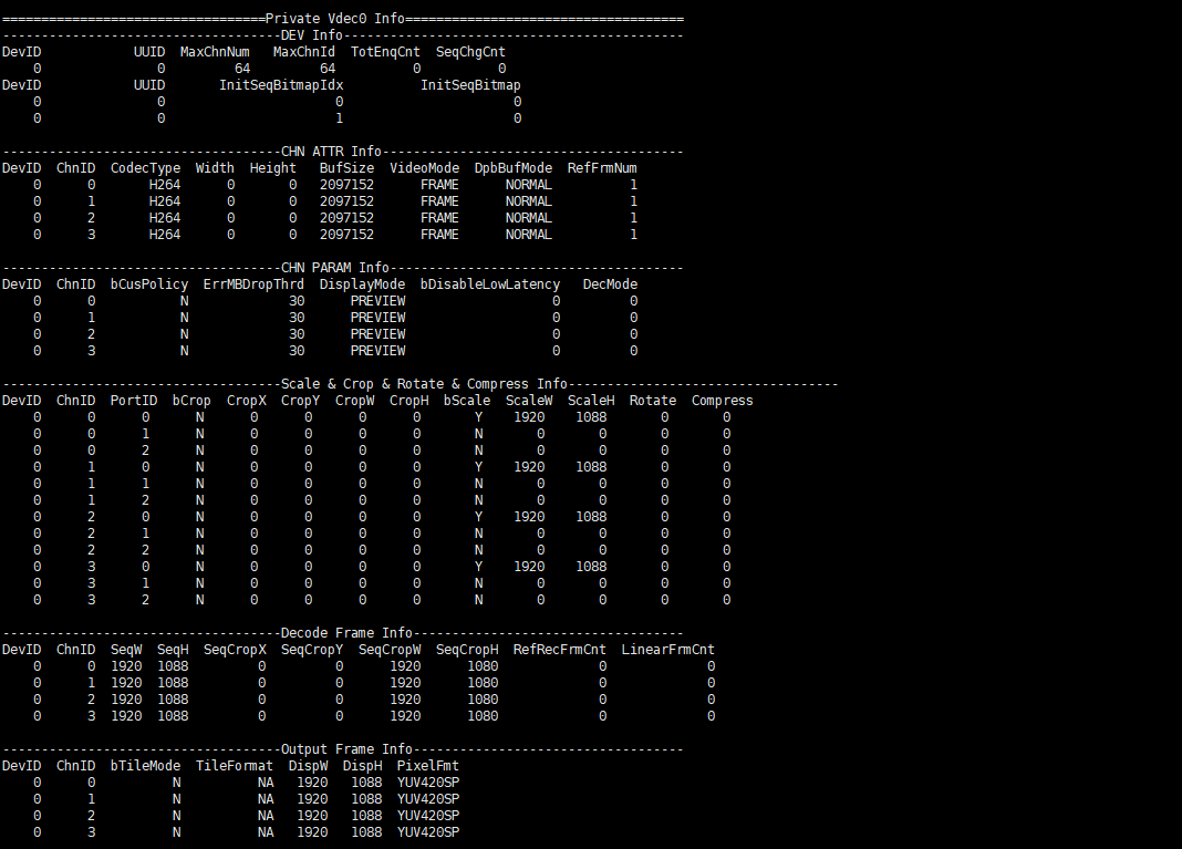
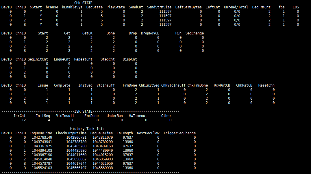
-
Debug Information Analysis
The printing is divided into two parts, separated by Private Vdec0 Info. The upper part is common information, and the lower part is vdec module information. It mainly records the usage and configuration attributes of the decoding channel, which can be used to check the attribute configuration and the working status of the current channel to facilitate debugging.
-
Parameter Description
Parameter Description DEV Info DevID Hardware device number UUID UUID MaxChnNum The maximum number of channels MaxChnId The maximum channel number TotEnqCnt The number of frames queued in the decoding hardware queue. InitSeqBitmapIdx Sequence initialization interrupt channel number bitmap index. InitSeqBitmap Sequence initialization interrupt channel number bitmap. SeqChgCnt Sequence change count. CHN ATTR Info DevID Hardware device number ChnID Channel ID CodecType Decoding protocol type.
0: H264;
1: H265;Width The maximum width of the decoded image. Height The maximum height of the decoded image. BufSize VDEC video stream buffer size, unit: byte. VideoMode Video stream send mode.
FRAME: Send by frame.DpbBufMode Decoding mode
INPLACE1: DBP_MODE_INPLACE_ONE_BUF;
INPLACE2: DBP_MODE_INPLACE_TWO_BUF;
NORMAL: DBP_MODE_NORMAL;RefFrmNum The maximum number of allocated reference frames. CHN PARAM Info DevID Hardware device number ChnID Channel ID bCusPolicy Whether customers set the drop frame policy
Y: Set by customers
N: Not set by customers, use defaultErrMBDropThrd When the drop frame policy is in effect, the ratio of error macroblocks to the entire data frame. DisplayMode PREVIEW
PLAYBACKbDisableLowLatency Whether the channel supports B-frame play.
0: Not support B-frame play.
1: Support B-frame play.DecMode Define video stream decoding mode
0: Decode IPB data frame.
1: Decode I frame only.
2: Decode IP frame only (B skipped).Scale & Crop & Rotate & Compress Info DevID Hardware device number. ChnID Channel ID PortID Port ID bCrop Whether to set crop function.
N: Not set.
Y: Set.CropX The starting abscissa of crop area. CropY The starting ordinate of crop area. CropW The width of crop area. CropH The height of crop area. bScale Whether to set scale function.
N: Not set, output according to the size of the source video stream.
Y: Set.ScaleW Set the width of the scale output. ScaleH Set the height of the scale output. Rotate Output image rotation angle.
0: no rotation.
1: Rotate 90 degrees clockwise.
2: Rotate 180 degrees clockwise.
3: Rotate 270 degrees clockwise.Compress Output image compression mode.
0: LSYC disabled.
10: LSYC enabled.Decode Frame Info DevID Hardware device number ChnID Channel ID SeqW The width of source video stream in sequence parameter set. SeqH The height of source video stream in sequence parameter set. SeqCropX The starting abscissa of crop area in sequence parameter set. SeqCropY The starting ordinate of crop area in sequence parameter set. SeqCropW The width of crop area in sequence parameter set. SeqCropH The height of crop area in sequence parameter set. RefRecFrmCnt The count of reference frames allocated for decoding of the current source video stream. LinearFrmCnt The number of Output Buffer allocated. Output Frame Info DevID Hardware device number ChnID Channel ID bTileMode Whether to open tilemode output format.
Y: Yes
N: NoTileFormat The alignment format after opening TileMode.
128x64: 128x64 Byte alignment.
128x32: 128x32 Byte alignment.
32x32: 32x32 Byte alignment.
Invalid: Not support.
NA: Not open tilemode output format.DispW The width of the output data frame. DispH The height of the output data frame. PixelFmt The pixel format of the output data frame.
YUV420SP: NV12 data frame format output.CHN STATE DevID Hardware device number ChnID Channel ID bStart Whether to start the decoder.
Y: Start, enter the decoding state
N: Stop the decoding state.bPause Whether the decoder is paused.
0: Non-pause decoding state
1: Paused decoding state.bEnableSys Whether decoding thread scheduling is enabled.
0: Disabled decoding scheduling
1: Enabled decoding scheduling.DecState The decoding state of the current channel.
0: Undefined.
1: The channel has just been created.
2: Wait for key data frames such as sps and pps.
3: Obtain information completion state of key sps, pps.
4: Before decoding, apply for the memory state of the reference frame and so on.
5: Apply for the memory required for decoding under normal decoding state.
6: The channel is closed.PlayState The play state of the current channel.
0: Normal play state.
1: Paused play state.
2: Refresh play state.
3: Step play state.SendCnt The count of video streams sent by the application layer. SendStrmSize The size of video streams sent by the application layer. LeftStrmBytes The bytes to be decoded in the stream buffer. LeftCnt Corresponding to SendCntParameter, the count to be decoded. Unread/Total The unread/total number of data entries in the stream buffer. DecFrmCnt The count of successfully decoded output frames. fps The current decoding frame rate. EOS Mark of bitstream data frame transmission completion. CHN STATE DevID Hardware device number ChnID Channel ID Start The count to start decoding. Get The count to get decoding result. GetOK The count the decoding result was successfully got. Done The count of successful decoding and output display. Drop The count that the display cannot be output is dropped. DropNoVCL The count that invalid data frames are dropped. Run The count to apply for hardware decoding. SeqChange The count the image sequence has changed.
For example: SPS.CHN STATE DevID Hardware device number ChnID Channel ID SeqInitCnt Sequence initialization task count. EnqueCnt Decoding task count. RefreshCnt Refresh task count. StepCnt Step task count. DispCnt Displayed frame count. CHN STATE DevID Hardware device number ChnID Channel ID Issue The frequency to apply for hardware decoding. Complete The frequency that the decoder completes decoding the video stream header information corresponding to an Issue request. InitSeq The interrupt frequency of decoding video stream head information returned from decoder corresponding to an Issue request. VlcInsuff The interrupt frequency of insufficient VLC Buffer. FrmDone The interrupt frequency of decoding done returned from decoder. ChkInitSeq Corresponding to InitSeq, the interrupt frequency checked by VDEC after the decoder completes decoding the video stream header information and returns interrupts. ChkVlcInsuff Corresponding to VlcInsuff, the interrupt frequency checked by VDEC after the decoder returns vlc buffer insufficient and returns interrupts. ChkFrmDone Corresponding to FrmDone, the interrupt frequency checked by VDEC after the decoder returns decoding success and interrupts. RcvRstCB The interrupt frequency of reset received from the decoder. ChkRstCB Corresponding to RcvRstCB, the interrupt frequency of reset checked by VDEC. ResetChnCnt Reset channel count. ISR STATE IsrCnt The count of interrupt frequency from decoder. InitSeq The interrupt frequency of decoding video stream head information reported by decoder. VlcInsuff The interrupt frequency of insufficient VLC Buffer reported by decoder. FrmDone The interrupt frequency of decoding done reported by decoder. UnderRun The frequency of under run task reported by decoder. HwTimeout The frequency of hardware time out reported by decoder. Other The other interrupt frequency reported by decoder. History Task Info DevID Hardware device number. ChnID Channel ID. EnqueueTime Time when the decoding task is enqueued. CheckOutputTime Time when the decoding task checks the output status. DequeueTime Time when the decoding task is dequeued. EsLength Length of the bitstream data sent for the decoding task. NextDecFlow The next decoding flow of the decoding task. TriggerSeqChange Whether the decoding task has triggered the sequence change process.
5.2. echo
vdec device 0:
/proc/mi_modules/mi_vdec/mi_vdec0
| Function | Open the debug log of capture or refresh to /proc/kmsg |
|---|---|
| Command | echo log [capture/refresh] [on/off] > /proc/mi_modules/mi_vdec/mi_vdec0 |
| Parameter Description | capture/refresh |
| on/off | |
| Example | echo log refresh on > /proc/mi_modules/mi_vdec/mi_vdec0 //Open the debug log of refresh to /proc/kmsg |
| Function | Dump the input bitstream data from the specified channel to the specified path |
|---|---|
| Command | echo dumpbs [chn] [path] > /proc/mi_modules/mi_vdec/mi_vdec0 |
| Parameter Description | chn: Channel ID [0~63] |
| path: The output path of dump file. Entering off means stop dumping bitstream | |
| Example | echo dumpbs 3 /mnt/dump/ > /proc/mi_modules/mi_vdec/mi_vdec0 //Dump the bitstream buffer data from channel 3 to /mnt/dump |
| Function | Dump all data of the current video stream buffer from the specified channel to the specified path. (The entire video stream buffer contains valid data and invalid data, pay attention to the difference with the previous dumpbs) |
|---|---|
| Command | echo dumpbsb [chn] [path] > /proc/mi_modules/mi_vdec/mi_vdec0 |
| Parameter Description | chn: Channel ID [0~63] |
| path: The output path of dump file. | |
| Example | echo dumpbsb 3 /mnt/dump/ > /proc/mi_modules/mi_vdec/mi_vdec0 //Dump the entire video stream buffer data from channel 3 to /mnt/dump |
| Function | Dump the decoded frames from the specified channel and the specified port to the specified path |
|---|---|
| Command | echo dumpfb [chn] [port] [path] [frmcnt] [bDumpAll] [bDetile] > /proc/mi_modules/mi_vdec/mi_vdec0 |
| Parameter Description | chn: Channel ID [0~63] |
| port: Port ID. | |
| path: The output path of dumped file. | |
| frmcnt: dumped frames | |
| bDumpAll: 0: Only dump yuv buffer. 1: Dump Y buffer, UV buffer and YUV buffer at the same time. | |
| bDetile: 0: Do not detile the YUV to be dumped (Tile format data is dumped in tilemode mode). 1: Detile the YUV to be dumped (YUV format data is dumped in tilemode mode). | |
| Example | echo dumpfb 3 0 /mnt/dump/ 99 0 1 > /proc/mi_modules/mi_vdec/mi_vdec0 //Channel 3, Port 0, the storage path is /mnt/dump/, dumps 99 frames, does not save Y buffer and UV buffer separately, and detiles the YUV to be stored |
| Function | Turn on/off flow checkpoint to check the running status of the decoding task. |
|---|---|
| Command | echo flowdbg [Status] > /proc/mi_modules/mi_vdec/mi_vdec0 |
| Parameter Description | Status: on / off |
| Example | echo flowdbg on > /proc/mi_modules/mi_vdec/mi_vdec0 //Turn on vdec flow checkpoint, and then enter cat /proc/mi_modules/mi_vdec/mi_vdec0 to view the checkpoints of multiple functions in vdec procfs. |
| Function | Turn on/off the frame drop switch, discard all decoded output data frames, and do not output to the decoded back end. |
|---|---|
| Command | echo dropoutbuf [Status] > /proc/mi_modules/mi_vdec/mi_vdec0 |
| Parameter Description | Status: on / off |
| Example | echo dropoutbuf on > /proc/mi_modules/mi_vdec/mi_vdec0 //Drop the frame buffer to be output. |
| Function | Turn on/off the vdec performance statistics switch, which will output more detailed proc debug information. |
|---|---|
| Command | echo setperf [Status] > /proc/mi_modules/mi_vdec/mi_vdec0 |
| Parameter Description | Status: on / off |
| Example | echo setperf on > /proc/mi_modules/mi_vdec/mi_vdec0 //Turn on the vdec performance statistics switch, and then enter cat /proc/mi_modules/mi_vdec/mi_vdec0 to view the current decoding time and other data in vdec procfs. |
| Function | Check the time interval consumed by each state of the decoding process. |
|---|---|
| Command | echo flowstat [chn] [on/off] > /proc/mi_modules/mi_vdec/mi_vdec0 |
| Parameter Description | chn: Channel ID [0~63] |
| on/off: on / off | |
| Example | echo flowstat 3 on > /proc/mi_modules/mi_vdec/mi_vdec0 //Turn on channel 3 to check that each state of the decoding process consumes time interval. |
| Function | Debug inside the refresh function. (Only for debug purposes, please use this under the assistance of technical support personnel.) |
|---|---|
| Command | echo refresh [chn] [pattern/dumpref/md5/clroutbuf] [on/off] [path] > /proc/mi_modules/mi_vdec/mi_vdec0 |
| Parameter Description | chn: Channel ID [0~63] |
| pattern/dumpref/md5/clroutbuf: pattern: Do not use the reference frame of the decoder, use the local file to decode and output the NV12 data frame. dumpref: The storage decoder is used to decode the reference frame of the output NV12. md5: Check whether all md5 values of the entire process of refresh are consistent, and check that the memory problem debug is turned on. clroutbuf: Clear the SCL output buffer data before transcoding. |
|
| on/off: on / off | |
| path: The path of local file and dumped file. | |
| Example | echo refresh 3 md5 on /mnt/dump/ > /proc/mi_modules/mi_vdec/mi_vdec0 //Turn on channel 3 to check the value of md5 of refresh. |
| Function | Force reset channel. (Equivalent to StopChn and then StartChn again. Only for debug purposes, please use this under the assistance of technical support personnel.) |
|---|---|
| Command | echo reset_chn [chn] > /proc/mi_modules/mi_vdec/mi_vdec0 |
| Parameter Description | chn: Channel ID [0~63] |
| Example | echo reset_chn 0 > /proc/mi_modules/mi_vdec/mi_vdec0 //Force reset channel 0. |