Bootlogo User Guide
1. Overview
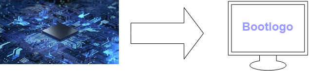
The bootlogo is the screen displayed when booting. It can be displayed on various LCD screens, including TTL, BT656, SRGB, and can also be displayed on MIPI screens.
This article will introduce how to configure and use bootlogo.
2. Compile configuration options
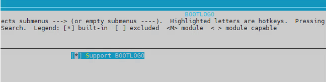
2.1 Open bootlogo

2.2 Partition select
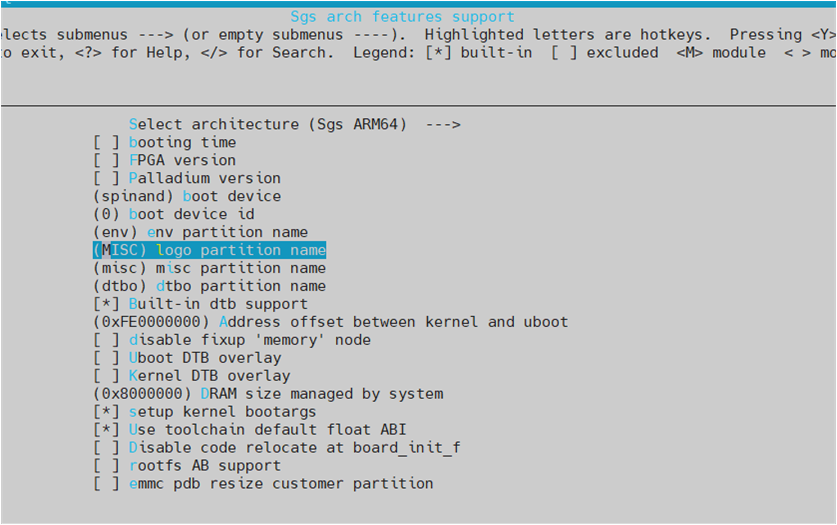
logo partition name: This partition stores images and screen parameters (config.json).
2.3 Open drivers
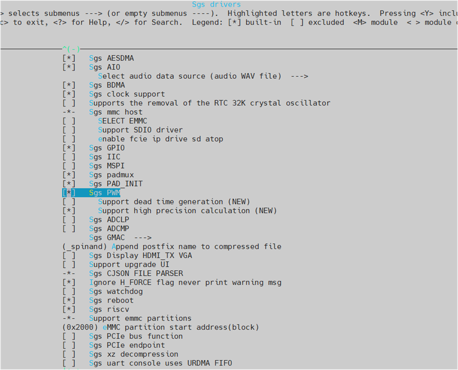
2.3.1 PWM
If the backlight needs to be controlled by PWM, then the PWM driver needs to be turned on.
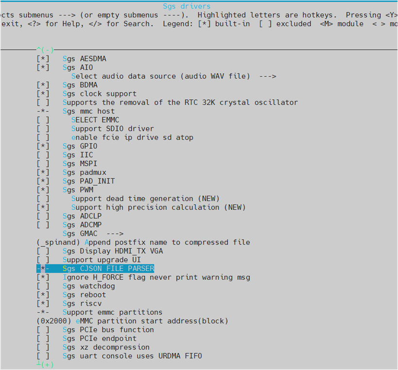
2.3.2 CJSON parser
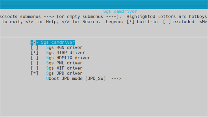
2.3.3 Open camdriver module
Sgs drivers ----> Sgs camdriver ----> Sgs DISP driver
Sgs drivers ----> Sgs camdriver ----> Sgs JPD driver
If you use gop display, you need to turn on
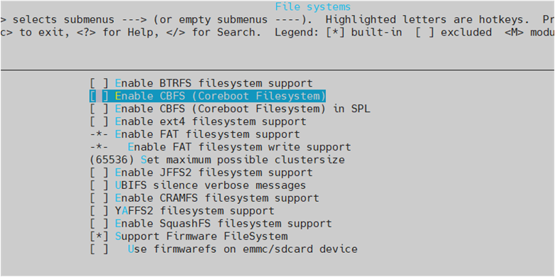
2.4 File systems
If the storage medium uses emmc, you need to select Use firmwarefs on emmc/sdcard device, otherwise it cannot be selected.
2.5 Open bootlogo requires files
3. Logo reserved buffer
This buffer is used for bootlogo display. If the kernel does not operate or release this address, it will remain displayed.
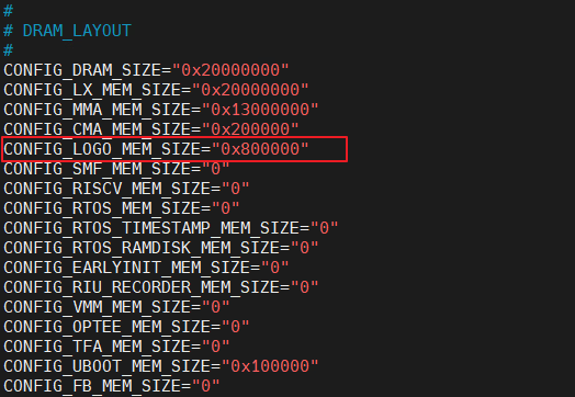
"CONFIG_LOGO_MEM_SIZE": The address configuration size where the logo is displayed.
After the above settings are completed, you can view the corresponding uboot environment variables on the board after burning. As shown in the figure below:

4. Padmux
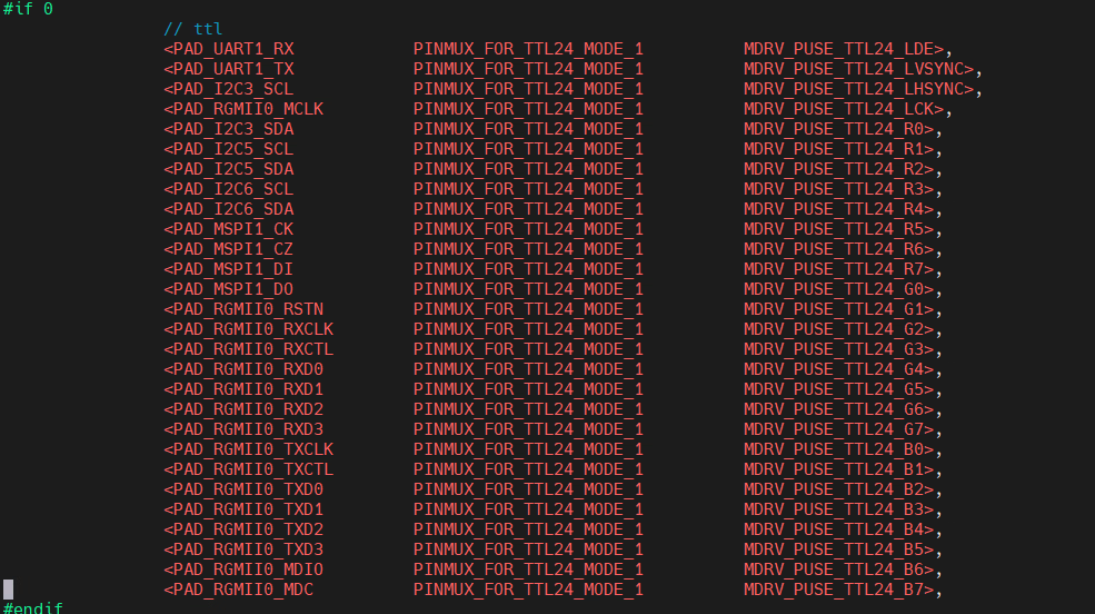
The screen needs to set padmux
For example, if you need to enable the TTL screen, you only need to change #if 0 to #if 1, as shown in the figure below
5. Logo storage location
If you want to put the pictures into the misc partition by default, you can modify the following location:

You can also copy the image to the misc partition after the board starts.
6. Bootlogo screen parameter configuration
Related file paths:
project\board\$(chip)\screen_param\config_disp.json
project\board\$(chip)\$(boardname)\config\config_board.json
config_disp.json stores panel parameters, while config_board.json specifies the panel parameters for bootlogo display, screen type, and other related settings. For detailed descriptions of config_disp.json and config_board.json, please refer to: Screen Parameter Usage Guide.
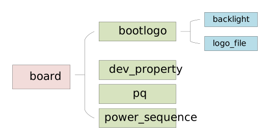
The following describes the nodes related to bootlogo within config_board.json. As illustrated in the diagram below, the bootlogo node contains two child nodes: backlight and logo_file. The backlight node describes backlight information, while logo_file specifies the path to the logo image file. In addition, config_board.json has a dev_property node at the same level as bootlogo, which specifies the interface type and panel parameter for bootlogo display, see below.
-
backlight
Parameters Description power_gpio gpio id of the power pin power_gpio_value power pin level
0: gpio active low
1: gpio active highpower_gpio_up_delay delay time after power on, the unit is ms power_gpio_down_delay delay time before power off, the unit is ms reset_gpio gpio id of reset pin reset_gpio_value reset pin level
0: gpio active low
1: gpio active highreset_gpio_up_delay delay time after power on, the unit is ms reset_gpio_down_delay delay time before power off, the unit is ms backlight_gpio gpio id of backlight pin backlight_gpio_value backlight pin level
0: gpio active low
1: gpio active highbacklight_gpio_up_delay delay time after enabling backlight, the unit is ms backlight_gpio_down_delay delay time before disabling backlight, the unit is ms pwm_channel The channel of PWM pwm_period PWM period, the unit is ns backlight_percent Backlight brightness percentage, range [0, 100], default 100 Note: backlight gpio is reserved for the backlight that does not require PWM control. The backlight can be enabled by pulling the gpio pin.
If PWM is used to configure the backlight, in addition to configuring pwm_channel, pwm_period, and backlight_percent, the PWM padmux of uboot also needs to be configured. PWM config must be enabled: PWM config.
For the query method of PWM channel, please refer to PWM USER GUIDE.
If there are special power-on and power-off timing sequences, please refer to MIPIDSI interface specific parameters.
During power on, the gpio pins are pulled in the order power_gpio -> reset_gpio -> backlight_gpio. After each pin is set to its value, the corresponding up_delay is waited. During power off, the pins are operated in reverse order and the down_delay is waited. Unconfigured gpio pins are not operated, and unconfigured delays are treated as 0.
Configuration example (power on with power gpio + control brightness with PWM):
"backlight": [
    {
        "power_gpio": 132,
        "power_gpio_value": 1,
        "power_gpio_up_delay": 10,
        "pwm_channel": 4,
        "pwm_period": 100000,
        "backlight_percent": 80
    }
]
In the example above, power_gpio = 132 is pulled high and then delayed for 10ms to complete power on. pwm_period = 100000 means the period is 100000 ns (i.e. 10kHz), and backlight_percent = 80 means a duty cycle of 80%. If a certain gpio or delay is not needed, just omit the corresponding parameter.
-
logo_file
logo_file is a JSON array. Each element is an object that contains the parameter logo_file_name, which specifies the storage path of the logo image.
Parameters Description logo_file_name storage path of the logo image The array index of an element is the logo_id of that logo: the first element has logo_id 0, the second has logo_id 1, and so on. At boot time, use the
bootlogo <logo_id>command to select which logo to display. For details on the logo_id parameter, see Introduction to bootlogo command.Configuration example (single logo):
"logo_file": [
    {
        "logo_file_name": "logo.jpg"
    }
]
Configuration example (multiple logos):
"logo_file": [
    {
        "logo_file_name": "logo.jpg"
    },
    {
        "logo_file_name": "logo_backup.jpg"
    }
]
For the default storage path and packaging method of logo images, see logo storage location.
Modifying the Maximum Number of Logos
The maximum number of elements supported by the logo_file array is limited by the macro
MAX_LOGO_FILE_NUM(default value is 2):boot/cmd/sgs/include/bootlogo_common.h #define MAX_LOGO_FILE_NUM (2)- If the number of array elements exceeds
MAX_LOGO_FILE_NUM, the excess elements will not be loaded. - If the logo_id specified by
bootlogo <logo_id>is greater than or equal toMAX_LOGO_FILE_NUM, an out-of-range error is reported and the logo cannot be displayed.
To support more logos, modify
MAX_LOGO_FILE_NUMto the desired value and rebuild uboot. - If the number of array elements exceeds
-
dev_property
dev_property is a node in config_board.json at the same level as bootlogo. It specifies the interface type and panel parameter used for bootlogo display. When you need to switch the bootlogo to a different interface (for example, from TTL to MIPIDSI), modify device_type and panel_name.
Parameter Description device_type Screen type (interface type), used by bootlogo
Values: TTL/BT656/SRGB/MCU/MCU_NOFLM/MIPIDSIpanel_name Panel parameter name, i.e. the section name of the corresponding panel parameter in config_disp.json; its interface type must match device_type dev_id device id rotate Rotation angle, used by bootlogo
0: 0°
90: 90°
180: 180°
270: 270°Steps to switch the interface:
- Confirm that the panel parameter for the target interface already exists (section name, e.g.
RM68200_LX50HDH40145). - Change device_type to the target interface type (e.g. TTL to MIPIDSI), and change panel_name to the section name of the corresponding panel parameter. device_type and panel_name just need to refer to the same panel parameter.
- Take effect by directly modifying the corresponding content of config.json on the board.
Configuration example (MIPIDSI panel):
"dev_property": [ { "device_type": "MIPIDSI", "panel_name": "RM68200_LX50HDH40145", "dev_id": 0, "rotate": 0 } ] - Confirm that the panel parameter for the target interface already exists (section name, e.g.
7. Introduction to bootlogo command
bootlogo [logo_id] [aspect_ratio] [x] [y] [device_id]

logo_id : image id. default is 0

aspect_ratio: 0: zoom, 1: center, 2: usr. default is 0

x : show horizontal start. it's valid when aspect_ratio is 2. default is 0

y : show vertical start. it's valid when aspect_ratio is 2. default is 0

device_id: device ID. default is 0

Example:

bootlogo // No parameters, all default parameters are 0

bootlogo 1 // Select the second logo to display, other parameters default to 0

bootlogo 0 1 // Select the first logo, and center the image

bootlogo 0 2 1 1 // Select the first logo, and start displaying the image from (1, 1)

bootlogo 0 0 0 0 0 // device id is 0
Note: The aspect ratio function requires the size of the input image to be smaller than the size of the screen output in order to work properly. This chip has only one device, and device_id can only be filled with 0.
8. Upgrade screen command introduction
8.1 Upgrade screen command
Note: Upgrading the screen display requires enabling GOP configuration. To enable configuration, please refer to open camdriver module
disp_ui_update [percentage/success/fail] [device_id]

percentage: percentage. range [0, 100]

device_id: device ID. default is 0

Example:

disp_ui_update 10 // The progress bar is 10%

disp_ui_update success // Upgrade successful

disp_ui_update fail // Upgrade failed
8.2 Separate commands for drawing UI
disp_ui bar [percentage] [bar_color] [text_color] [bg_color] [device_id]

bar : draw progress bar

percentage: percentage. range [0, 100]

bar_color: show bar color. fmt is rgb(bit[23, 0]). default is green

text_color: show text color. default is white

bg_color : show bar background. default is blue

device_id: device ID. default is 0

Example:

disp_ui bar 10 // The progress bar is 10%

disp_ui bar 10 0xff00 // 10% progress bar color is green

disp_ui bar 10 0xff00 0xffffff // 10% of the progress bar is green, and 10% of the characters are white

disp_ui bar 10 0xff00 0xffffff 0xffffff // The background color of the progress bar is white, the color of the 10% progress bar is green, and the color of the 10% text is white

disp_ui bar 10 0xff00 0xffffff 0xffffff 0 // device id is 0
disp_ui msg [text] [x] [y] [text_color] [bg_color] [device_id]

msg : draw characters

text : ascii text. default is blank

x : show text horizontal start. default is 0

y : show text vertical start. default is 0

text_color: show text color. default is white

bg_color : show bar background. default is blue

device_id: device ID. default is 0

Example:

disp_ui msg update \\ Draw the character "update", starting from (0, 0) by default

disp_ui msg update 1 1 \\ Start drawing the character "update" from (1, 1)

disp_ui msg update 1 1 0xffffff \\ Character color is white

disp_ui msg update 1 1 0x0 0xffffff \\ Character color black, background color white

disp_ui msg update 1 1 0x0 0xffffff 0 \\ device id is 0
disp_ui blank [x] [y] [w] [h] [BlankColor] [device_id]

blank : erase

x : erase horizontal start. default is 0

y : erase vertical start. default is 0

w : erase the length. default is 0

h : erase the width. default is 0

BlankColor: erase the color. default is blue

device_id: device ID. default is 0

Example:

disp_ui blank 1 1 10 10 \\ Erase the area with a width and height of 10 at the starting point (1, 1), and the color is blue

disp_ui blank 1 1 10 10 0xffffff \\ The erase color is black

disp_ui blank 1 1 10 10 0xffffff 0 \\ device id is 0