GMAC DEBUG SOP
REVISION HISTORY
| Revision No. | Description |
Date |
|---|---|---|
| 1.0 | 06/10/2025 | |
| 1.1 | 05/20/2026 |
Issue 1: Unable to Ping
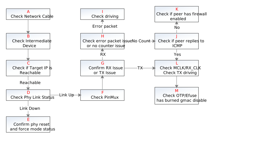
| Step | Method | Exit Condition | Next Step or Conclusion | Info to Provide to FAE | Notes & Related FAQ |
|---|---|---|---|---|---|
| A | Swap the network cable with a known-working network environment for cross-validation testing | Exit Condition 1: Not a cable issue Exit Condition 2: Cable issue |
Exit Condition 1: ==> B Exit Condition 2: End ==> Cable issue |
||
| B | Connect the intermediate device (switch or router) in a known-working network environment | Exit Condition 1: Network is normal after connecting the intermediate device Exit Condition 2: Network is still unreachable after connecting the intermediate device |
Exit Condition 1: ==> C Exit Condition 2: End ==> Intermediate device issue |
||
| C | After executing ping, check whether it shows "Network unreachable" or hangs | Exit Condition 1: Hangs ==> Network is reachable Exit Condition 2: Network unreachable ==> LAN configuration error (e.g., gateway, IP subnet, IP table, etc.) |
Exit Condition 1: ==> D Exit Condition 2: End ==> Network configuration issue |
||
| D | Method 1: Unplug and re-plug the network cable, check the link up/down logs Method 2: Read the link status bit from the PHY register |
Exit Condition 1: Link down or no link-up log Exit Condition 2: Link up |
Exit Condition 1: ==> E Exit Condition 2: ==> F |
Link status can be checked via the PHY register bank_phy0 offset1 bit2 : 1: Link is up 0: Link is down phy_wr node path /proc/gmac_0/phy_wr Usage: echo phy_r phyid phyaddress > phy_wr echo phy_w phyid phyaddress phyvalue > phy_wr e.g.: echo phy_r 0 1 > phy_wr Or use ./phytool read eth0/0/1 |
|
| E | 1. Confirm whether the PHY in use has been properly reset 2. Use ethtool to check whether it is currently in force mode. If so, verify that the force mode configuration on both sides is consistent |
Exit Condition 1: PHY has been properly initialized with reset, and either it is not in force mode, or link-up still fails after both sides have consistent force mode configuration Exit Condition 2: Link up after resolving the above issues |
Exit Condition 1: End ==> Report to FAE Exit Condition 2: End ==> PHY negotiation issue |
Provide debug logs, boot logs, reset pull-low/pull-high signal waveform captures, and GMAC-related register information | Command: ./ethtool eth0 |
| F | Reference board: Check the padmux in the corresponding dtsi to see whether the corresponding GPIO pin has conflicts or is configured to another GPIO mode. Custom board: Check whether pins are incorrectly multiplexed based on the customer's actual pin design |
Exit Condition 1: Pin configuration is normal Exit Condition 2: Pin configuration is abnormal |
Exit Condition 1: End ==> G Exit Condition 2: End ==> Pin configuration abnormal |
Provide debug info, boot logs, and register information |
|
| G | Run ifconfig, ping for a period, then run ifconfig again to check statistics If the TX packet count increment is 0, there is an issue in the TX direction If the RX packet count increment is 0, or errors increase, there is an issue in the RX direction |
Exit Condition 1: RX issue Exit Condition 2: TX issue Exit Condition 3: Neither of the above (both have counts) ==> May be a network environment issue |
Exit Condition 1: ==> H Exit Condition 2: ==> L Exit Condition 3: End ==> Report to FAE for environment analysis |
ifconfig logs before and after, GMAC-related register information Packet captures from the test device and board Network configuration on both sides (IP address, MAC address, ARP table, routing table, etc.) |
If neither has counts, troubleshoot RX first, then TX |
| H | If rx packets is 0, it is a no-counter issue If there is an rx error count, it is an error packet issue |
Exit Condition 1: No counter issue Exit Condition 2: Error packet issue |
Exit Condition 1: ==> J Exit Condition 2: ==> I |
||
| I | Adjust the driving according to the PHY manual, then retry ping to see if it succeeds | Exit Condition 1: Can successfully ping Exit Condition 2: No error count increase, but still cannot ping Exit Condition 3: Error count continues to increase |
Exit Condition 1: End ==> Driving issue Exit Condition 2: ==> H Exit Condition 3: End ==> Contact CAE to check for hardware issues |
Provide serial logs, ifconfig info, dlist info, and register information RX CLK/DATA waveform captures |
Waveform measurement can be used for debugging at this step to ensure the adjusted driving meets requirements |
| J | 1. Launch Wireshark on the PC; start tcpdump capture on the board. 2. Board pings the PC; observe packet exchange to check whether the board sends ICMP requests and whether the PC responds with ICMP replies |
Exit Condition 1: Board sends no ICMP packets Exit Condition 2: PC sends no ICMP packets |
Exit Condition 1: ==> L Exit Condition 2: ==> K |
||
| K | Verify whether the PC/test device has a firewall enabled that filters ICMP packets sent by the board | Exit Condition 1: Firewall is enabled Exit Condition 2: Firewall is not enabled |
Exit Condition 1: End ==> Disable the firewall; it may be blocking the board's packets Exit Condition 2: End ==> May be a network environment issue; contact FAE for analysis if needed |
ifconfig logs before and after Packet captures from the test device and board Network configuration on both sides (IP address, MAC address, ARP table, routing table, etc.) |
|
| L | RMII: Use an oscilloscope to check whether the REF_CLK waveform is normal (if a waveform is present, verify the frequency is 50 MHz / 25 MHz) RGMII: Check whether MCLK meets PHY requirements and whether TX pin driving meets PHY requirements |
Exit Condition 1: CLK abnormal or pin driving abnormal Exit Condition 2: CLK normal / pin driving normal |
Exit Condition 1: End ==> Contact FAE to confirm CLK configuration / TX driving configuration Exit Condition 2: ==> M |
Provide serial logs, debug info, ifconfig info, and register information | cat /proc/gmac_0/driving => Print current IO driving setting echo [io_idx] [gear] > /proc/gmac_0/driving => Set io_idx to the specified gear level |
| M | Use a tool to read the OTP/Efuse disable gmac bit (contact the OTP owner for assistance if unsure of the method) | Exit Condition 1: Read result is 00 or 11 ==> Not disabled Exit Condition 2: Read result is 10 or 01 ==> Disabled |
Exit Condition 1: End ==> Contact FAE for further troubleshooting Exit Condition 2: End ==> OTP has disabled the network |
Provide a screenshot of the OTP read result |
Issue 2: Network Not Working Under U-Boot
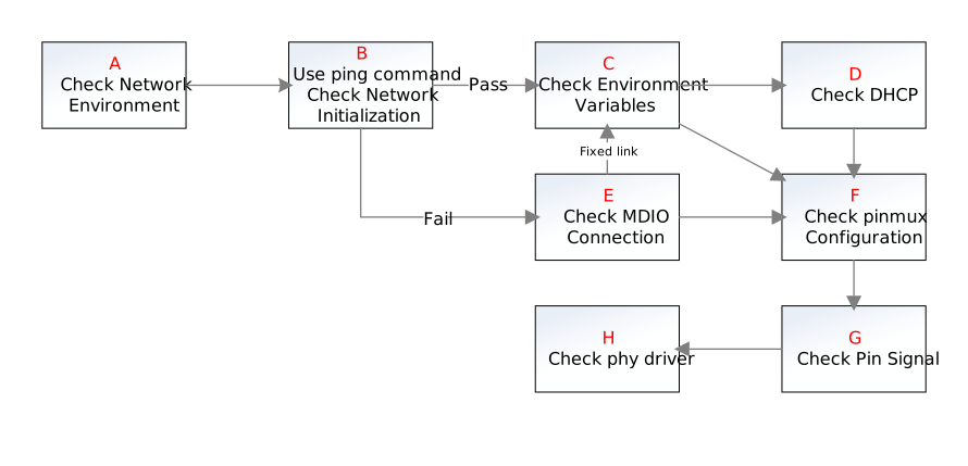
| Step | Method | Exit Condition | Next Step | Info to Provide to FAE | Notes & Related FAQ |
|---|---|---|---|---|---|
| A | Connect the peer device's network cable to another device with a known-working network, and test whether the network is normal | Exit Condition 1: Network is normal Exit Condition 2: Network is abnormal |
Exit Condition 1: ==> B Exit Condition 2: End ==> Peer device abnormal |
||
| B | Use the ping command to check whether the device is properly initialized | Exit Condition 1: Normal initialization Exit Condition 2: Not properly initialized |
Exit Condition 1: ==> C Exit Condition 2: ==> E |
||
| C | Check whether the environment variable configuration is correct | Exit Condition 1: Environment variable configuration is correct, and is using dynamic IP (DHCP) Exit Condition 2: Environment variable configuration is correct, and is using static IP Exit Condition 3: Environment variable configuration is incorrect |
Exit Condition 1: ==> D Exit Condition 2: ==> F Exit Condition 3: End ==> Re-test after correcting the configuration |
gmac0 Static IP Configuration Reference: setenv -f ethact gmac0 setenv -f ethaddr xx:xx:xx:xx:xx:xx setenv -f ipaddr xxx.xxx.xxx.xxx setenv -f netmask xxx.xxx.xxx.xxx |
|
| D | Check DHCP 1. Switch to a static IP address to communicate with other devices 2. Change to a different MAC address, then try DHCP to see if it can ping the PC |
Exit Condition 1: Static IP still cannot ping Exit Condition 2: Static IP can ping, or network is normal |
Exit Condition 1: ==> F Exit Condition 2: End ==> DHCP abnormal |
gmac0 Dynamic IP Configuration Reference: setenv -f ethact gmac0 setenv -f ethaddr xx:xx:xx:xx:xx:xx dhcp |
|
| E | Verify whether the MDIO connection is normal | Exit Condition 1: MDIO connection abnormal Exit Condition 2: MDIO connection normal Exit Condition 3: Configured with fixed-link |
Exit Condition 1: ==> F; check MDIO pin Exit Condition 2: ==> F Exit Condition 3: ==> C |
Run dhcp/ping command and check for "Could not get PHY for gmacX: addr -1"; this log indicates a MDIO connection issue "gmacx Waiting for PHY auto negotiation to complete...... done" indicates the MDIO connection is normal |
|
| F | Based on the customer's actual layout, check whether the MII pins have pin multiplexing conflicts | Exit Condition 1: pinmux has no multiplexing conflicts Exit Condition 2: pinmux has multiplexing conflicts, and network still not working after fix Exit Condition 3: pinmux has multiplexing conflicts, and network recovers after fix |
Exit Condition 1: ==> G Exit Condition 2: ==> G Exit Condition 3: End ==> pinmux configuration error |
Troubleshooting logs Troubleshooting experiments and experiment result records |
MII here refers to the data interface between MAC and PHY, including RGMII, RMII, and other types |
| G | Use an LA or oscilloscope to measure signals/waveforms; observe: 1. High level around 3.3 V, low level 0 V 2. Whether the waveform is normal and noise-free 3. Whether the phase is normal |
Exit Condition 1: Signal/waveform normal Exit Condition 2: Signal/waveform abnormal |
Exit Condition 1: End ==> H Exit Condition 2: End ==> Contact CAE for further troubleshooting |
Troubleshooting logs Troubleshooting experiments and experiment result records |
1. Voltage abnormalities may require checking jumper caps, etc.; contact CAE for analysis 2. Waveform abnormality with noise may indicate cold solder joints on the chip 3. PHY reset abnormal |
| H | Check whether the PHY driver is adapted | Exit Condition 1: PHY driver adapted Exit Condition 2: PHY driver not adapted |
Exit Condition 1: End ==> Report to FAE Exit Condition 2: End ==> Use the correct PHY driver and continue testing |
Troubleshooting logs Troubleshooting experiments and experiment result records GMAC register information |
Check whether the PHY in use requires a specific driver, and whether the corresponding PHY driver option was selected during compilation |
Issue 3: Insufficient Network Bandwidth
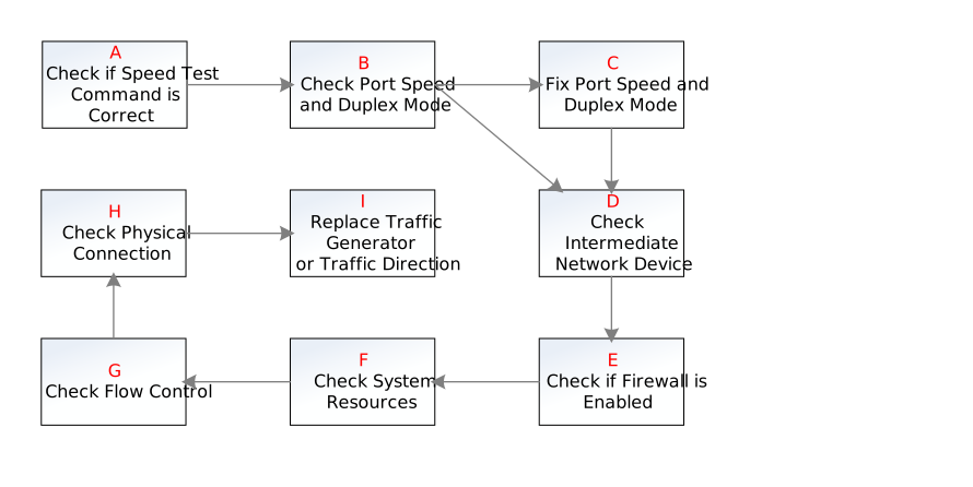
| Step | Method | Exit Condition | Next Step | Info to Provide to FAE | Notes & Related FAQ |
|---|---|---|---|---|---|
| A | Check whether the speed-test tool commands are correct. Common issues include: 1. iperf requires the -b option to specify maximum bandwidth when measuring UDP bandwidth 2. iperf2 requires both server and client to use -u for proper UDP send/receive |
Exit Condition 1: Command is correct Exit Condition 2: Command is incorrect |
Exit Condition 1: ==> B Exit Condition 2: End ==> Tool usage issue |
iperf and other test tool server- and client-side logs | iperf3 server: ./iperf3 -s [-i 1] [-p \<port-id>] iperf3 client: ./iperf3 -c \<remote-ip> [-p \<port-id>] [-i 1] [-t 36000] [-u] [-R] |
| B | 1. Check the port speed and duplex mode 2. Check whether the speed/duplex mode matches the peer port 3. Check whether the port has a large number of error packets |
Exit Condition 1: Everything is normal Exit Condition 2: Abnormality detected (low port speed, speed/duplex mode mismatch, large number of error packets, etc.) |
Exit Condition 1: ==> D Exit Condition 2: ==> C |
Query ethx port basic settings: ./ethtool ethx Check port error packets / RX statistics: Command: ifconfig -S ethx |
|
| C | 1. Use ethtool to fix the speed and duplex mode on both ends, then re-test | Exit Condition 1: Bandwidth still insufficient Exit Condition 2: Bandwidth is normal |
Exit Condition 1: ==> D Exit Condition 2: End ==> Auto-negotiation issue |
Set ethx speed/duplex mode/auto-negotiation: ./ethtool -s ethx [speed 10|100|1000] [duplex half|full] [autoneg on|off] |
|
| D | Check the intermediate device Method: Use direct connection to test device bandwidth |
Exit Condition 1: Bandwidth still insufficient under direct connection Exit Condition 2: Bandwidth is normal under direct connection |
Exit Condition 1: ==> E Exit Condition 2: End ==> Intermediate device rate limiting |
This may be caused by QoS policies or bandwidth-limiting policies on the intermediate device (router, switch) | |
| E | Check whether the device and auxiliary devices used for bandwidth testing (e.g., PC) have firewalls enabled. If so, disable the firewall and re-test | Exit Condition 1: No firewall enabled, or bandwidth still insufficient with firewall disabled Exit Condition 2: Bandwidth returns to normal with firewall disabled |
Exit Condition 1: ==> F Exit Condition 2: End ==> Firewall-related cause |
||
| F | During bandwidth testing, use the top command to observe system resource usage. Pay attention to: 1. Whether there is free memory (Mem: xxx free) 2. Whether there is idle CPU (CPU: xx% idle) |
Exit Condition 1: System resources are sufficient Exit Condition 2: System resources are insufficient |
Exit Condition 1: ==> G Exit Condition 2: End ==> Performance issue |
idle indicates idle resources. The lower the idle, the higher the CPU load (CPU load = 100% - idle) Some versions of top differ from the common one; you can use: busybox top -d 1 -d 1 sets the refresh interval to 1 s |
|
| G | Disable flow control on the device and the directly connected peer device, then re-test bandwidth | Exit Condition 1: Bandwidth returns to normal Exit Condition 2: Bandwidth still insufficient |
Exit Condition 1: End ==> Flow control causing insufficient bandwidth Exit Condition 2: ==> H |
Check TX/RX flow control packet count: ./ethtool -S ethx Disable device flow control: ./ethtool -A ethx rx off tx off Check current flow control status: ./ethtool -a ethx |
|
| H | 1. Unplug and re-plug the network cable, then re-test 2. Replace with a known-working network cable, then re-test |
Exit Condition 1: Bandwidth returns to normal Exit Condition 2: Bandwidth still insufficient |
Exit Condition 1: End ==> Physical connection issue Exit Condition 2: End ==> Report to FAE |
Troubleshooting logs Troubleshooting experiments and experiment result records GMAC bank register dump data |
|
| I | Try changing the traffic direction or traffic test device 1. Use iperf with the -R option to reverse traffic direction 2. Replace with the same model device using the same image |
Exit Condition 1: Bandwidth returns to normal Exit Condition 2: Bandwidth still insufficient |
Exit Condition 1: End ==> Hardware issue; contact CAE for troubleshooting Exit Condition 2: End ==> Report to FAE |
Provide testing-related logs | If bandwidth is normal after changing the traffic direction or device, try a different server- or client-side device to determine whether the original device has a TX-side or RX-side issue (or both) |
Issue 4: Frequent Network Disconnection
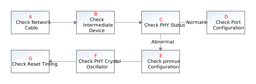
| Step | Method | Exit Condition | Next Step | Info to Provide to FAE | Notes & Related FAQ |
|---|---|---|---|---|---|
| A | Check whether frequent disconnection is caused by cable quality Swap the network cable with a known-working network environment for cross-validation testing |
Exit Condition 1: Not a cable issue Exit Condition 2: Cable issue |
Exit Condition 1: ==> B Exit Condition 2: End ==> Cable issue |
||
| B | Check whether the issue is caused by the network environment Test with direct connection to see if frequent disconnection still occurs |
Exit Condition 1: Frequent disconnection still occurs with direct connection Exit Condition 2: Network is normal |
Exit Condition 1: ==> C Exit Condition 2: End ==> Network environment or intermediate device issue |
||
| C | Check the PHY status register to see if it changes frequently, and whether the read link status matches the current state | Exit Condition 1: PHY status normal Exit Condition 2: External PHY and PHY status abnormal Exit Condition 3: Internal PHY and PHY status abnormal |
Exit Condition 1: ==> D Exit Condition 2: ==> E Exit Condition 3: End ==> Report to FAE |
Debug logs | Link status can be checked via the PHY register bank_phy0 offset1 bit2 : 1: Link is up 0: Link is down PHY register read method: phytool read IFACE/ADDR/REG echo phy_r 0 1 > /proc/gmac_0/phy_wr |
| D | Check whether the device port configuration (duplex mode/speed) matches the peer port. If not, configure the matching port mode and re-test. Check whether the network returns to normal | Exit Condition 1: Returns to normal Exit Condition 2: Does not return to normal |
Exit Condition 1: End ==> Network port mode mismatch issue Exit Condition 2: End ==> Report to FAE |
Debug logs and register information | Command: ./ethtool eth0 |
| E | Check the pinmux of the connected pins; ensure all are set to the correct mode, and no pin occupation exists | Exit Condition 1: pinmux normal Exit Condition 2: pinmux abnormal |
Exit Condition 1: ==> F Exit Condition 2: End ==> pinmux abnormal |
||
| F | Use an oscilloscope to check whether the PHY crystal oscillator pin waveform is normal | Exit Condition 1: Waveform normal Exit Condition 2: Waveform abnormal |
Exit Condition 1: ==> G Exit Condition 2: End ==> PHY crystal oscillator damaged |
||
| G | According to the reset timing requirements in the PHY manual or switch manual, verify the actual configured reset timing | Exit Condition 1: Reset flow correct Exit Condition 2: Reset flow incorrect |
Exit Condition 1: End ==> Report to FAE Exit Condition 2: End ==> Adjust the reset flow and re-test |
Troubleshooting logs Troubleshooting experiments and experiment result records GMAC bank register dump data |
Default: pull reset pin low for 20 ms, then pull high for 50 ms Customers may have modified these values; verify the actual reset timing meets requirements Also verify the reset pin selection is correct and no pinmux multiplexing conflict exists |
Issue 5: New ePHY or Switch NIC Model Adaptation Failure

| Step | Method | Exit Condition | Next Step | Info to Provide to FAE | Notes & Related FAQ |
|---|---|---|---|---|---|
| A | Check whether the PHY or switch pins are physically connected to the chip. Check for any loose connections | Exit Condition 1: Physical connection is normal Exit Condition 2: Not properly connected |
Exit Condition 1: ==> B Exit Condition 2: End ==> Physical connection abnormal |
||
| B | Check the pinmux of the connected pins; ensure all are set to the correct mode, and no pin occupation exists | Exit Condition 1: pinmux normal Exit Condition 2: pinmux abnormal |
Exit Condition 1: ==> C Exit Condition 2: End ==> pinmux abnormal |
||
| C | According to the reset timing requirements in the PHY manual or switch manual, verify the actual configured reset timing | Exit Condition 1: Timing normal, reset pin configuration correct Exit Condition 2: Timing incorrect, or reset pin is occupied |
Exit Condition 1: ==> D Exit Condition 2: End ==> Reset pin error |
Default: pull reset pin low for 20 ms, then pull high for 50 ms Customers may have modified these values; verify the actual reset timing meets requirements Also verify the reset pin selection is correct and no pinmux multiplexing conflict exists |
|
| D | Verify whether fixed-link is enabled | Exit Condition 1: Enabled, or fixed-link is not needed Exit Condition 2: Not enabled |
Exit Condition 1: ==> E Exit Condition 2: End ==> fixed-link not enabled |
Switch NIC adaptation, or when PHY status is not a concern (no MDIO, etc.), requires enabling fixed-link | |
| E | Check whether the PHY/switch clock meets the requirements in the PHY/switch manual | Exit Condition 1: Yes Exit Condition 2: No |
Exit Condition 1: ==> F Exit Condition 2: End ==> Clock mismatch causing adaptation failure |
||
| F | Confirm with the PHY vendor or switch vendor whether a driver update is needed | Exit Condition 1: Not needed Exit Condition 2: Needed |
Exit Condition 1: End ==> Contact FAE for further troubleshooting Exit Condition 2: End ==> Driver update required |
Troubleshooting logs Troubleshooting experiments and experiment result records GMAC bank register dump data |
Issue 6: Network Abnormality Under Gigabit Bandwidth
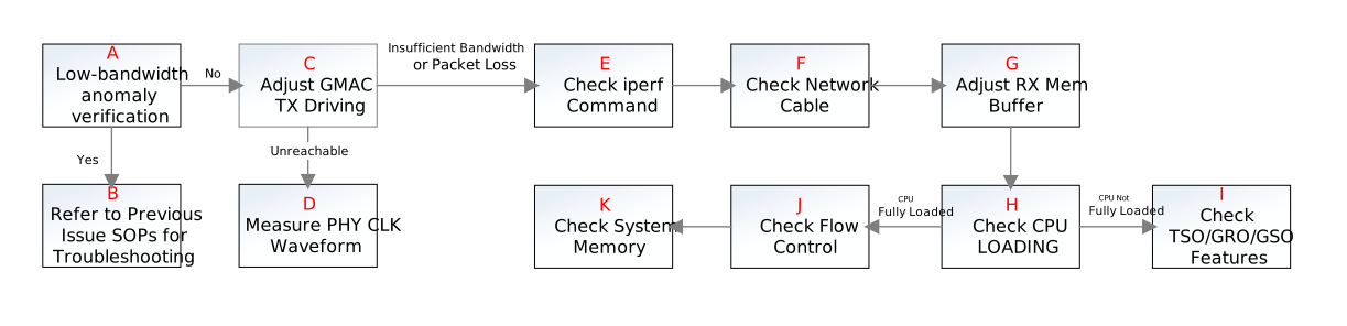
| Step | Method | Exit Condition | Next Step or Conclusion | Info to Provide to FAE | Notes & Related FAQ |
|---|---|---|---|---|---|
| A | Use ethtool to change the interface speed; check whether the abnormality persists | Exit Condition 1: Returns to normal Exit Condition 2: Abnormality persists |
Exit Condition 1: ==> C Exit Condition 2: ==> B |
ethtool command example: Configure eth0 interface to 100 Mbps full duplex: ethtool -s eth0 speed 100 duplex full |
|
| B | Refer to the earlier issue flows in this SOP for troubleshooting | Exit Condition 1: ALL | Exit Condition 1: End | ||
| C | Adjust the GMAC TX driving and confirm whether the network recovers | Exit Condition 1: Returns to normal Exit Condition 2: Abnormality persists, and the issue is network unreachable Exit Condition 3: Abnormality persists, and the issue is insufficient bandwidth or packet loss |
Exit Condition 1: End ==> GMAC TX driving issue; modify the default driving in code to an appropriate level Exit Condition 2: ==> D Exit Condition 3: ==> E |
cat /proc/gmac_0/driving => Print current IO driving setting echo [io_idx] [gear] > /proc/gmac_0/driving => Set io_idx to the specified gear level |
|
| D | Use an LA or oscilloscope to measure the PHY CLK waveform; observe: 1. High level around 3.3 V, low level 0 V 2. Whether the waveform is normal and noise-free 3. Whether the phase is normal |
Exit Condition 1: Signal/waveform normal Exit Condition 2: Signal/waveform abnormal |
Exit Condition 1: End ==> Contact FAE for further troubleshooting Exit Condition 2: End ==> Contact CAE to investigate CLK waveform abnormality |
Troubleshooting logs Troubleshooting experiments and experiment result records |
|
| E | Check whether the iperf command is used correctly | Exit Condition 1: Used correctly Exit Condition 2: Used incorrectly |
Exit Condition 1: ==> F Exit Condition 2: End ==> Re-test with the correct command |
Check for the following common issues: 1. iperf requires the -b option to specify bandwidth when testing UDP e.g.: iperf -c 192.168.1.1 -u -b 1G 2. iperf may fail to achieve full bandwidth on UDP RX because the default UDP buffer length is too small; use the -l option to increase the RX buffer size e.g.: iperf -c 192.168.1.1 -u -R -b 1G -l 65500 |
|
| F | Replace with a cable known to support full gigabit speed, then re-test | Exit Condition 1: Returns to normal Exit Condition 2: Abnormality persists |
Exit Condition 1: End ==> Cable issue Exit Condition 2: ==> G |
The device supports 100 Mbps bandwidth at 100 meters, and 10 Mbps bandwidth at 250 meters Using a cable that is too long at gigabit speed will cause unreachability or abnormalities At gigabit speeds, it is recommended to use Cat 6 cable; substandard cable quality can also cause poor network performance |
|
| G | Adjust the RX memory buffer size, then re-test | Exit Condition 1: Returns to normal Exit Condition 2: Abnormality persists |
Exit Condition 1: End ==> Insufficient RX buffer size issue Exit Condition 2: ==> H |
RX buffer size adjustment commands: echo 20971520 > /proc/sys/net/core/rmem_max echo 20971520 > /proc/sys/net/core/rmem_default |
|
| H | Use the top command to check whether CPU load is at 100% during gigabit network usage | Exit Condition 1: Full load Exit Condition 2: Not full load |
Exit Condition 1: ==> G Exit Condition 2: ==> H |
CPU usage can be determined by the remaining idle, i.e., the (CPU: xx% idle xx% io) field When idle is 0% and IO is at full load, the CPU is fully loaded |
|
| I | Use ethtool to check whether GMAC TSO, GRO, GSO, and other offload features are enabled 1. Enable all GSO/GRO/TSO features and test the network condition 2. Disable all GSO/GRO/TSO features and test the network condition |
Exit Condition 1: Both enabled and disabled are ineffective; network still abnormal Exit Condition 2: Network returns to normal when all features are enabled Exit Condition 3: Network returns to normal when all features are disabled |
Exit Condition 1: End ==> Report to FAE for further troubleshooting Exit Condition 2: End ==> Features not enabled causing excessive interrupts and high CPU load, leading to network abnormality Exit Condition 3: End ==> Feature function anomaly (hardware issue); report to FAE and have FAE assist HWRD in troubleshooting |
ethtool command to view netdev features: ethtool -k eth0 (network interface) ethtool command to configure netdev features: Example: Enable GSO feature on eth0 interface: ethtool -K eth0 gso on |
|
| J | Use ethtool to check the number of pause frames; compare with normal condition. If excessively high, disable flow control on the device and peer, then re-test | Exit Condition 1: Returns to normal Exit Condition 2: Abnormality persists |
Exit Condition 1: End ==> Excessive flow control packets issue Exit Condition 2: End ==> I |
Troubleshooting logs Troubleshooting experiments and experiment result records |
Decide based on circumstances whether to involve FAE for further troubleshooting |
| K | Check system memory to see whether there is insufficient memory | Exit Condition 1: Insufficient memory Exit Condition 2: Memory is sufficient |
Exit Condition 1: End ==> Report to memory owner for initial troubleshooting Exit Condition 2: End ==> Report to GMAC owner for further troubleshooting |
Troubleshooting logs Troubleshooting experiments and experiment result records GMAC-related registers |
Command to check system memory: cat /proc/meminfo |
GMAC-Related Registers
| Module | Addr |
|---|---|
| gmac0 | 0x1510 |
| gmac1 | 0x1513 |
| net_gp_ctrl | 0x1512 |
| X32_GMAC0 | 0x1A50 0x1A51 0x1A52 0x1A53 0x1A54 0x1A55 0x1A56 0x1A57 |
| X32_GMAC1 | 0x1A5A 0x1A5B 0x1A5C 0x1A5D 0x1A5E 0x1A5F 0x1A60 0x1A61 |
| GMACPLL | 0x103A |
| PADTOP | 0x103C |
| CLKGEN | 0x1038 |
| CLKGEN2 | 0x103F |
| PAD_GPIO | 0x103E |
| PAD_GPIO2 | 0x1104 |
| INTR_CTRL1_1 | 0x1017 |