MI RGN API
REVISION HISTORY
| Revision No. | Description |
Date |
|---|---|---|
| 3.0 | 12/04/2020 | |
| 08/25/2021 | ||
| 02/16/2022 | ||
| 03/21/2022 | ||
| 02/13/2023 | ||
| 11/10/2023 | ||
| 11/13/2023 | ||
| 03/18/2024 | ||
| 04/17/2024 | ||
| 3.1 | 05/30/2024 | |
| 08/20/2024 | ||
| 08/26/2024 | ||
| 08/28/2024 | ||
| 12/27/2024 | ||
| 04/24/2025 | ||
| 05/14/2025 | ||
| 08/25/2025 | ||
| 11/07/2025 |
1. OVERVIEW
1.1. Module Description
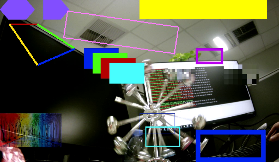
The region module is a part of an internal stream processing in some Pipeline modules. It is supported by hardware module named GOP (graphic output path), MFF (Mosaic and Face Frame). And it is a set of software interface abstracted by hardware characteristics. OSD (on screen display), COVER and so on attaches to each channel in the way of using time sharing multiplexing.
The region module mainly provides the control and management functions of region resources. It includes the creation, destruction, acquisition and the setting of region attributes, acquisition and the setting of channel display attributes of the region, etc.
There are four kinds of region attributions:
-
COVER
-
COVER has two modes.
- Color mode. Making a solid color occlusion of an area according to the settings, the driver only needs to know the position, size, and color.
- Mosaic mode. Mosaicking an area according to the settings, the driver only needs to know the position, size, and block size.
-
COVER can be divided into rectangular COVER and polygonal COVER according to the area type (minimum 3-sided, maximum 6-sided, only convex polygons are supported), among which rectangular COVER does not consume additional memory. The channel which attached Polygonal COVER need COVER bitmap.
-
-
OSD, also called ‘overlay’, which is same to 'COVER'. It can be attached to the display video area worked by display buffer, so this kind of region can do drawing operation in point to point way, and the color format of ‘OSD’ can support argb(true color format) and bitmap. User can choose the color format according to the practical application scenarios.
-
FRAME, draw a rectangular frame in the specified area of the video according to the settings. The underlying driver only needs to know the position, size, color and line width of the rectangular frame. It does not consume additional memory.
-
LINE, is determined by two pairs of coordinates. The width of the line can be specified, and both solid and hollow lines are supported. The width of the line border is specified by hollow lines. It does not consume additional memory.
Currently OSD format supports ‘ARGB1555’, ‘ARGB4444’, ‘ARGB8888’, ‘RGB565’, ‘I2’, ‘I4’, ‘I8’. The format supporting conditions of each chip will be different. The following will be explained in details. YUV format is not supported. I2, I4 and I8 are in bitmap format, and the memory data of a pixel is used as an index. Through the index, the color data in the color palette can be found, which the pixel displays is.
‘OSD’ always display on the top layer. Diff chip, diff layer between COVER, FRAME and LINE.
The region types and features supported on different chips and modules are different. Please read the chip difference instructions carefully before using module RGN!!
1.1.1 Keyword
-
I2
4 colors bitmap, 2 bits refer to an index, so that there are 4 colors. It can find the color by the index in palette.
-
I4
16 colors bitmap, 4 bits refer to an index and find the color by the index in palette.
-
I8
256 colors bitmap, 8 bits refer to an index and find the color by the index in palette.
-
Palette
The palette of bitmap, one color is represented by four 8bit variables: alpha, red, green and blue, there are totally 256 colors in palette with index range from 0 to 255.
-
OSD
Abbreviation of on-screen display, It is used to display some text, pictures, UI menus and other contents.
-
GOP
Abbreviation of graphic output path, it is a graphic layer above video.
-
MFF
Uniform name of COVER + FRAME + LINE.
1.2. Basic Structure

1.3. Module Function
-
Support region management: Manage different region types such as OSD, COVER, FRAME and LINE.
-
Support multiple formats: OSD supports True Color and Indexed formats. COVER, FRAME and LINE support YUV format.
-
Support multi-channel processing: Can process of channels across different modules.
-
Support multiple graphic overlays: OSD, COVER, FRAME and LINE can be overlaid for display.
1.4. Application Scenario
Applications can be developed based on the API interface provided by MI_RGN on LINUX, RTOS and DUALOS.
1.4.1. OSD scenario and memory usage instructions
In order to ensure that the OSD can be output to the video stably, RGN allocates one or more buffers to each OSD according to the hardware/user usage to prevent writing to the buffer being used for hardware display, causing OSD flickering or tearing.
The following will increase the memory usage of RGN:
- The update speed of the upper layer OSD(call MI_RGN_SetBitMap/MI_RGN_GetCanvasInfo/MI_RGN_UpdateCanvas) is accelerated;
- The number of channels superimposed on an OSD has increased;
- The number of OSDs superimposed on a channel at the same time exceeds the maximum hardware layers. For the maximum number of hardware layers supported by each chip, please see 'Table 1-5: Chip information of Tiramisu', 'Table 1-6: Chip information of Muffin', 'Table 1-7: Chip information of Mochi', 'Table 1-8: Chip information of Maruko', 'Table 1-9: Chip information of Opera', 'Table 1-10: Chip information of Souffle', 'Table 1-12: Chip information of Iford', 'Table 1-14: Chip information of Ifado', 'Table 1-14: Chip information of Pcupid', 'Table 1-15: Chip information of Ifackel', 'Table 1-20: Chip information of Ibopper','Table 1-21: Chip information of Jaguar1','Table 1-26: Chip information of Ifliegen','Table 1-29: Chip information of Ihalo'.
The following table lists the buffer usage in common scenarios:
Table 1-1:OSD buffer use
| Scenario Description | OSD | OSD refresh rate t/each time |
Channel | buffer |
|---|---|---|---|---|
| 1 OSD attached to 1 channel, only attached once without refreshing | 1 | NA | 1 | 1 |
| 1 OSD attached to 1 channel, slow refresh | 1 | 1s | 1 | 2 |
| 1 OSD attached to 1 channel, fast refresh | 1 | 30ms | 1 | 3 |
| 1 OSD attached n channels, only attached once without refreshing | 1 | NA | n | 1 |
| 1 OSD attached n channels, slow refresh | 1 | 1s | n | 2 |
| 1 OSD attached n channels, fast refresh | 1 | 30ms | n | [3, 2n+1] |
| m OSDs attached to 1 channel, only attached once without refreshing | m <= L | NA | 1 | m |
| m OSDs attached to 1 channel, slow refresh | m <= L | 1s | 1 | 2m |
| m OSDs attached to 1 channel, fast refresh | m <= L | 30ms | 1 | 3m |
| m OSDs attached to n channels, only attached once without refreshing | m <= L | NA | n | m |
| m OSDs attached to n channels, slow refresh | m <= L | 1s | n | 2m |
| m OSDs attached to n channels, fast refresh | m <= L | 30ms | n | [3m, m(2n+1)] |
| m OSDs attached to n channels, only attached once without refreshing | m > L | NA | n | L + n(m - L) |
| m OSDs attached to n channels, slow refresh | m > L | 1s | n | 2L + 2n(m - L) |
| m OSDs attached to n channels, fast refresh | m > L | 30ms | n | [3L, L(2n+1)] + 3n(m–L) |
Note:
- L represents the maximum number of hardware layers;
- For example, [3, 2n+1] represents a closed interval, and the number of buffers is a certain value in this interval (affected by system scheduling, it usually does not reach the maximum value).
- The above buffer usage only applies when the user does not limit the number of osd buffers, if the maximum number of OSD buffers is specified by MI_RGN_Create, the maximum number of OSD buffers is subject to the setting.
1.4.2. COVER scenario and memory usage instructions
COVER is divided into rectangular COVER and polygonal COVER according to the area type. The polygonal COVER in the current channel requires at least 1 buffer. Buffer length = (Screen width/8) (aligned 16 upwards) * Screen height, in bytes. Note: The screen width and height here is the resolution of the current channel.
The following table lists the buffer usage in common scenarios:
Table 1-2:COVER buffer use
| Scenario Description | Channel | Minimum Buffer | Maximum Buffer |
|---|---|---|---|
| 1 or multiple polygonal COVER attached to 1 channel, no refresh | 1 | 1 | 1 |
| 1 or multiple polygonal COVER attached to 1 channel, slow refresh | 1 | 2 | 2 |
| 1 or multiple polygonal COVER attached to 1 channel, fast refresh | 1 | 2 | 3 |
| 1 or multiple polygonal COVER attached to n channels, no refresh | n | n | n |
| 1 or multiple polygonal COVER attached to n channels, slow refresh | n | 2n | 2n |
| 1 or multiple polygonal COVER attached to n channels, fast refresh | n | 2n | 3n |
1.4.3. Color invert scenario and memory usage instructions
Color invert running in AUTO mode requires at least 1 buffer per channel. MANUAL mode requires at least 2 buffer per channel. Buffer size = (Screen width/Horizontal block size of color invert) (aligned 16 upwards) * (Screen height/Vertical block size of color invert), in bytes. Note: The screen width and height here is the resolution of the current channel.
The following table lists the buffer usage in common scenarios:
Table 1-3:Color invert buffer use
| Scenario Description | Color Invert Mode | Minimum Buffer | Maximum Buffer |
|---|---|---|---|
| Color invert multiple frames in a channel | AUTO | 1 | 1 |
| Color invert multiple frames in a channel | MANUAL | 3 | 5 |
| Color invert multiple frames in m channels | AUTO | m | m |
| Color invert multiple frames in m channels | MANUAL | 3m | 5m |
1.5. Chip Difference
1.5.1 General instructions
The differences among chips mainly lie in the following aspects: (1)Channel type, (2)Hardware layer count of OSD, (3)OSD color invert, (4)Frame count, (5)Cover countt, (6)Mosaic mode, (7)Polygonal Cover, (8)Color formats.
-
Channel type: types of channels supported by the chip.
-
Hardware layer count of OSD: the count of OSD supported by the channel.
-
OSD color invert: whether the channel supports OSD color invert.
-
Frame count: the count of Frame supported by the channel.
-
Cover count: the count of Cover supported by the channel.
-
Mosaic mode: whether the channel supports Mosaic mode.
-
Polygonal Cover: whether the channel supports Polygonal Cover.
-
Color formats: whether the channel supports the color format.
Note: Before reading the chip difference, please refer to the legend below.

-
The RGN's hardware in some chips can be used by MI_RGN or MI_FB. The same RGN's hardware cannot be used by two modules at the same time.
-
There are reused RGN's hardware, and there are certain restrictions on the use of channels that reference the same RGN's hardware. That is, channels that may work at the same time cannot reference the same RGN's hardware at the same time.
Table 1-4: RGN's hardware reuse rules
| Channel relationship(Unmentioned relations can be any value) | Can RGN be attached at the same time | Example | Explanation |
|---|---|---|---|
| Different Mod | No | Any channel of SCL and any channel of DISP | Different Mod has independent hardware. Will work at the same time. |
| Same Mod, different Dev | No | SCL Dev0 and SCL Dev1 | Same Mod, different Dev, has independent hardware. Will work at the same time. |
| Same Mod and Dev, different Chn | Yes | SCL Dev0 Chn0 and SCL Dev0 Chn1 | Same Mod and Dev is is a hardware timing-sharing multiplexing. Will not work at the same time. |
| Same Mod, Dev, Chn and Port type, but different PortId. | No | SCL Dev0 Chn0 OutputPort0 and SCL Dev0 Chn0 OutputPort1 | Same Mod, Dev, Chn. Will work at the same time. |
| Same Mod, Dev, Chn, different Port type. | No | SCL Dev0 Chn0 InputPort0 and SCL Dev0 Chn0 OutputPort0 | Same Mod, Dev, Chn. Will work at the same time. |
1.5.2 Tiramisu
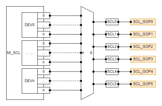
- This chip RGN can only attach the OSD on SCL.
- Each device on the SCL has 6 output port(which id from 0 to 5), and each output port can exclusively occupy a SCL_GOP hardware.
- Each SCL output port corresponds to a COVER hardware. Different COVER hardware is independent of each other and can be used at the same time.
Table 1-5: Chip information of Tiramisu
| Channel type | Hardware layer count of OSD | OSD color invert | Frame count | Cover count | Mosaic mode | Polygonal Cover | ARGB1555/ARGB4444/I2/I4/I8 | ARGB8888/RGB565 |
|---|---|---|---|---|---|---|---|---|
| SCL_OUTPUT_PORT | 8 | NA | NA | 4 | NA | NA | Y | NA |
1.5.3 Muffin
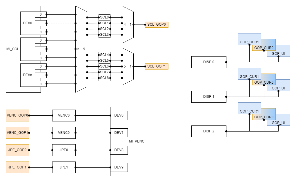
- The GOP_CUR0 of the chip is used to display the OSD for RGN, and the other is used to display the UI and cursor for the MI_FB module.
- Each device on the SCL has 9 output port(which id from 0 to 8), the output port(0-3) need to share the SCL_GOP0 hardware, the output port(4-8) need to share the SCL_GOP1 hardware.
- Each SCL output port corresponds to a COVER hardware. Different COVER hardware is independent of each other and can be used at the same time.
- The device0 on the VENC exclusively occupy the VENC_GOP0 hardware, the device1 exclusively occupy the VENC_GOP1 hardware, the device8 exclusively occupy the JPE_GOP0 hardware, the device9 exclusively occupy the JPE_GOP1 hardware.
- SCL GOP will be reuesd by multiple SCL hardware, please refer to Table 1-4: RGN's hardware reuse rules.
Table 1-6: Chip information of Muffin
| Channel type | Hardware layer count of OSD | OSD color invert | Frame count | Cover count | Mosaic mode | Polygonal Cover | ARGB1555/ARGB4444/I2/I4/I8 | ARGB8888/RGB565 |
|---|---|---|---|---|---|---|---|---|
| SCL_OUTPUT_PORT | 8 | NA | NA | 4 | NA | NA | Y | NA |
| VENC | 8 | NA | NA | NA | NA | NA | Y | NA |
| JPE | 8 | NA | NA | NA | NA | NA | Y | NA |
| DISP | 1 | NA | NA | NA | NA | NA | Y | NA |
1.5.4 Mochi
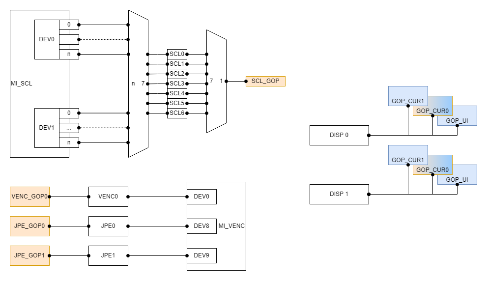
- The GOP_CUR0 of the chip is used to display the OSD for RGN, and the other is used to display the UI and cursor for the MI_FB module.
- Each device on the SCL has 7 output port(which id from 0 to 6), all the output port need to share the SCL_GOP hardware.
- Each SCL output port corresponds to a COVER hardware. Different COVER hardware is independent of each other and can be used at the same time.
- The device0 on the VENC exclusively occupy the VENC_GOP0 hardware, the device8 exclusively occupy the JPE_GOP0 hardware, the device9 exclusively occupy the JPE_GOP1 hardware.
Table 1-7: Chip information of Mochi
| Channel type | Hardware layer count of OSD | OSD color invert | Frame count | Cover count | Mosaic mode | Polygonal Cover | ARGB1555/ARGB4444/I2/I4/I8 | ARGB8888/RGB565 |
|---|---|---|---|---|---|---|---|---|
| SCL_OUTPUT_PORT | 8 | NA | NA | 4 | NA | NA | Y | NA |
| VENC | 8 | NA | NA | NA | NA | NA | Y | NA |
| JPE | 8 | NA | NA | NA | NA | NA | Y | NA |
| DISP | 1 | NA | NA | NA | NA | NA | Y | NA |
1.5.5 Maruko
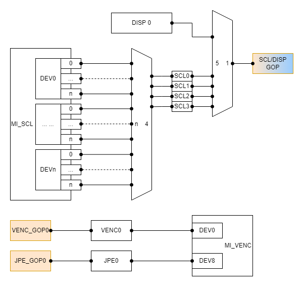
- Each device on the SCL has 4 output port(which id from 0 to 3), and all the output port need to share the GOP hardware with DISP (which means at the same time only SCL or DISP can use the hardware).
- Each SCL output port corresponds to a COVER hardware. Different COVER hardware is independent of each other and can be used at the same time.
- The device0 on the VENC exclusively occupy the VENC_GOP0 hardware, the device8 exclusively occupy the JPE_GOP0 hardware.
- SCL GOP will be reuesd by multiple SCL hardware or DISP hardware, please refer to Table 1-4: RGN's hardware reuse rules.
Table 1-8: Chip information of Maruko
| Channel type | Hardware layer count of OSD | OSD color invert | Frame count | Cover count | Mosaic mode | Polygonal Cover | ARGB1555/ARGB4444/I2/I4/I8 | ARGB8888/RGB565 |
|---|---|---|---|---|---|---|---|---|
| SCL_OUTPUT_PORT | 8 | NA | NA | 4 | NA | NA | Y | Y |
| VENC | 8 | NA | NA | NA | NA | NA | Y | NA |
| JPE | 8 | NA | NA | NA | NA | NA | Y | NA |
| DISP | 8 | NA | NA | NA | NA | NA | Y | Y |
1.5.6 Opera
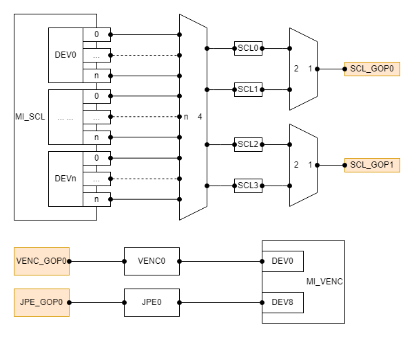
- Each device on the SCL has 4 output port(which id from 0 to 3), the output port(0-1) need to share SCL_GOP0 hardware, the output port(2-3) need to share the SCL_GOP1 hardware.
- Each SCL output port corresponds to a COVER hardware. Different COVER hardware is independent of each other and can be used at the same time.
- The device0 on the VENC exclusively occupy the VENC_GOP0 hardware, the device8 exclusively occupy the JPE_GOP0 hardware.
- SCL GOP will be reuesd by multiple SCL hardware, please refer to Table 1-4: RGN's hardware reuse rules.
Table 1-9: Chip information of Opera
| Channel type | Hardware layer count of OSD | OSD color invert | Frame count | Cover count | Mosaic mode | Polygonal Cover | ARGB1555/ARGB4444/I2/I4/I8 | ARGB8888/RGB565 |
|---|---|---|---|---|---|---|---|---|
| SCL_OUTPUT_PORT | 8 | Y | NA | 4 | NA | NA | Y | Y |
| VENC | 8 | Y | NA | NA | NA | NA | Y | NA |
| JPE | 8 | Y | NA | NA | NA | NA | Y | NA |
| DISP | 1 | NA | NA | NA | NA | NA | Y | NA |
1.5.7 Souffle
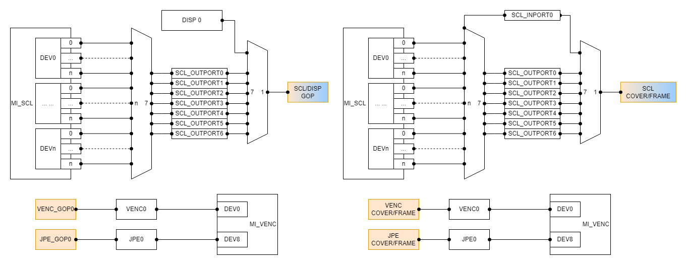
- Each device on the SCL has 7 output port(which id from 0 to 6) and 1 input port. SCL needs to share the GOP hardware with DISP (which means at the same time only SCL or DISP can use the hardware). SCL exclusively occupy the COVER/FRAME hardware.
- SCL input port and output port with the same id need to share access to a COVER hardware. Different id corresponds to different COVER hardware, COVER hardware is independent of each other and can be used at the same time.
- The device0 on the VENC exclusively occupy the VENC_GOP0 and the VENC_COVER/FRAME hardware, the device8 exclusively occupy the JPE_GOP0 and the JPE_COVER/FRAME hardware.
- SCL GOP will be reuesd by multiple SCL hardware or DISP hardware, please refer to Table 1-4: RGN's hardware reuse rules.
- SCL COVER and FRAME will be reuesd by multiple SCL hardware, please refer to Table 1-4: RGN's hardware reuse rules.
- The layer of different types of regions on the same channel are OSD, FRAME, and COVER(Contains color mode COVER and mosaic modeCOVER) from top to bottom.
- There can only be up to 16 colors each for COVER and FRAME in the same channel color mode, and the same color can be reused.
- SCL COVER and FRAME can only be attached to the same SCL at the same time.
- The rectangles COVER and the polygons COVER' Layer are calculated separately, rectangles COVER is above of polygons COVER.
- All polygonal COVER of the same channel must be the same mode, color mode COVER should be same color, mosaic mode Mosaic shouldbe same block size.
- The platform supports attach multiple OSD with different pixel formats on the same channel at the same time.
Table 1-10: Chip information of Souffle
| Channel type | Hardware layer count of OSD | OSD color invert | Frame count | Cover count | Mosaic mode | Polygonal Cover | ARGB1555/ARGB4444/I2/I4/I8 | ARGB8888/RGB565 |
|---|---|---|---|---|---|---|---|---|
| SCL_INPUT_PORT | NA | NA | 32 | 32 | Y | Y | NA | NA |
| SCL_OUTPUT_PORT | 8 | Y | 32 | 32 | Y | Y | Y | Y |
| VENC | 8 | Y | 32 | 64 | Y | NA | Y | NA |
| JPE | 8 | Y | 32 | 64 | Y | NA | Y | NA |
| DISP | 8 | NA | NA | NA | NA | NA | Y | Y |
Table 1-11: The support situation of mosaic mode block size
| Channel type | block size 4 | block size 8 | block size 16 | block size 32 | block size 64 | block size 128 | block size256 |
|---|---|---|---|---|---|---|---|
| SCL_INPUT_PORT | N | Y | Y | Y | Y | Y | Y |
| SCL_OUTPUT_PORT | N | Y | Y | Y | Y | Y | Y |
| VENC | Y | Y | Y | Y | N | N | N |
| JPE | Y | Y | Y | Y | N | N | N |
1.5.8 Iford
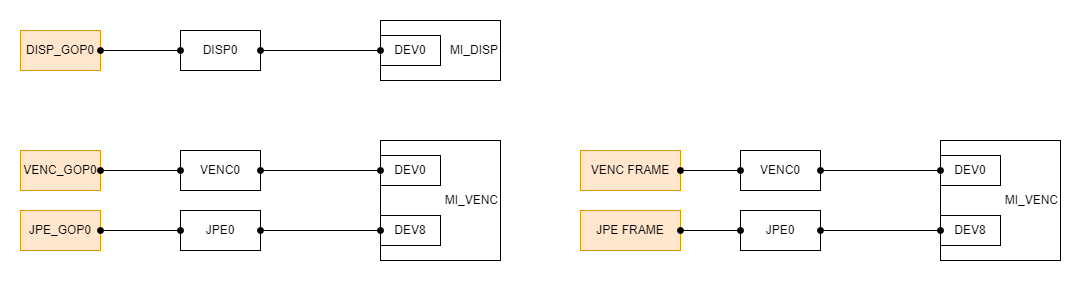
- The device0 on the DISP exclusively occupy the DISP_GOP0 hardware.
- Each SCL output port corresponds to a COVER hardware. Different COVER hardware is independent of each other and can be used at the same time.
- The device0 on the VENC exclusively occupy the VENC_GOP0 and the VENC_FRAME hardware, the device8 exclusively occupy the JPE_GOP0 and the JPE_FRAME hardware.
- The layer of different types of regions on the VENC or JPE channel are OSD, FRAME from top to bottom.
- There can only be up to 16 colors each for COVER and FRAME in the same channel color mode, and the same color can be reused.
- The GOP hardware for implementing OSD in DISP and the hardware for displaying UI in MI_FB in this chip are the same, and onlyone of them can be used at the same time.
- The platform supports attach multiple OSD with different pixel formats on the same channel at the same time.
Table 1-12: Chip information of Iford
| Channel type | Hardware layer count of OSD | OSD color invert | Frame count | Cover count | Mosaic mode | Polygonal Cover | ARGB1555/ARGB4444/I2/I4/I8 | ARGB8888/RGB565 |
|---|---|---|---|---|---|---|---|---|
| SCL_OUTPUT_PORT | NA | NA | NA | 4 | NA | NA | NA | NA |
| VENC | 4 | NA | 32 | NA | NA | NA | Y | NA |
| JPE | 4 | NA | 32 | NA | NA | NA | Y | NA |
| DISP | 4 | NA | NA | NA | NA | NA | Y | Y |
1.5.9 Ifado
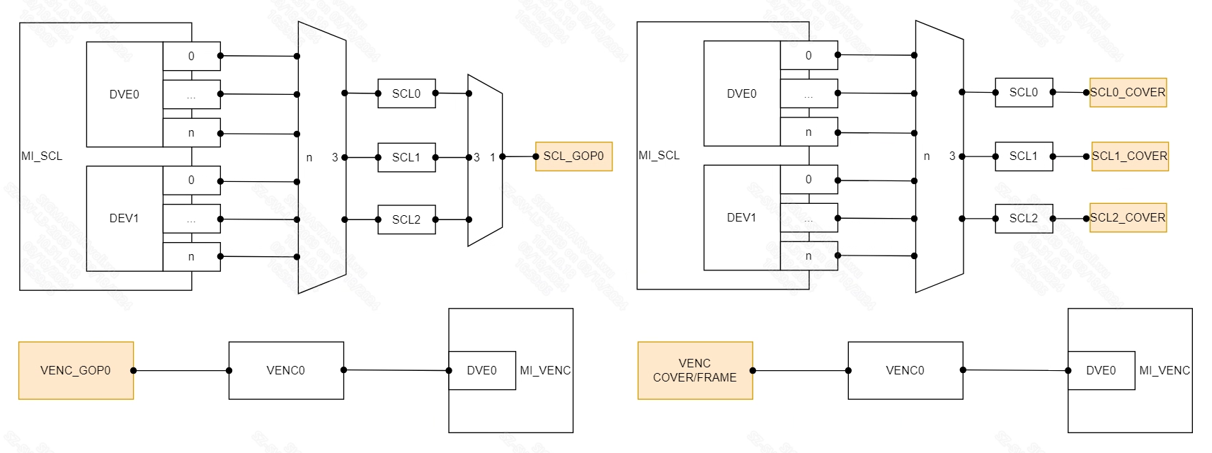
- Each device on the SCL has 3 output port(which id from 0 to 2), the output port(0-2) need to share SCL_GOP0 hardware.
- Each SCL output port corresponds to a COVER hardware. Different COVER hardware is independent of each other and can be used at the same time.
- The layer of different types of regions on the SCL channel are OSD, COVER from top to bottom.
- The device0 on the VENC exclusively occupy the VENC_GOP0 and the VENC_COVER/FRAME hardware.
- The layer of different types of regions on the VENC channel are OSD, MFF(Contains FRAME, color mode COVER and LINE) from top tobottom.
- VENC's COVER, FRAME and LINE are implemented by the same hardware. The three types of RGN on the same channel are counteduniformly, that is, the channel can attach a total of 16 areas of these three types at the same time.
- The levels of VENC's COVER, FRAME and LINE are determined by the u32Layer parameter. The level of the area with a larger valuemust be above the area with a smaller value.
- COVER, FRAME and LINE can only have up to 16 colors in the same channel color mode, and the same color can be used repeatedly.
- SCL GOP will be reuesd by multiple SCL hardware, please refer to Table 1-4: RGN's hardware reuse rules.
- The platform supports attach multiple OSD with different pixel formats on the same channel at the same time.
Table 1-13: Chip information of Ifado
| Channel type | Hardware layer count of OSD | OSD color invert | Frame count | Cover count | LINE count | Solid LINE | Hollow LINE | ARGB1555/I2/I4 | ARGB4444/RGB565/I8 |
|---|---|---|---|---|---|---|---|---|---|
| SCL_OUTPUT_PORT | 4 | NA | NA | 4 | NA | NA | NA | Y | Y |
| VENC | 4 | NA | 16 | 16 | 16 | Y | Y | Y | NA |
1.5.10 Pcupid
- This chip RGN can only attach the COVER on SCL.
- Each SCL output port corresponds to a COVER hardware. Different COVER hardware is independent of each other and can be used at the same time.
Table 1-14: Chip information of Pcupid
| Channel type | Hardware layer count of OSD | OSD color invert | Frame count | Cover count | Mosaic mode | Polygonal Cover | ARGB1555/ARGB4444/I2/I4/I8 | ARGB8888/RGB565 |
|---|---|---|---|---|---|---|---|---|
| SCL_OUTPUT_PORT | NA | NA | NA | 4 | NA | NA | NA | NA |
1.5.11 Ifackel
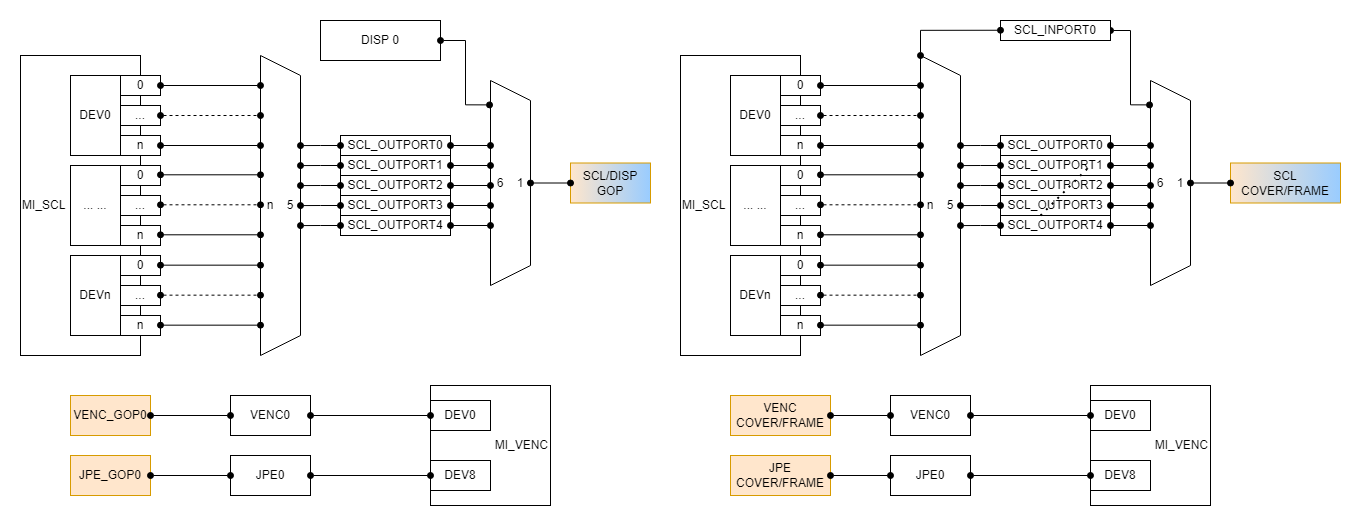
- Each device on the SCL has 4 output port(which id from 0 to 4) and 1 input port. All the output port need to share the GOP hardware with DISP (which means at the same time only SCL or DISP can use the hardware). SCL exclusively occupy the COVER/FRAME hardware.
- The device0 on the VENC exclusively occupy the VENC_GOP0 and VENC_COVER/FRAME hardware, the device8 exclusively occupy the JPE_GOP0 and JPE_COVER/FRAME hardware.
- SCL GOP will be reuesd by multiple SCL hardware or DISP hardware, please refer to Table 1-4: RGN's hardware reuse rules.
- The platform supports attach multiple OSD with different pixel formats on the same channel at the same time.
Table 1-15:OSD support information
| Channel type | Hardware layer count of OSD | OSD color invert | ARGB1555/ARGB4444/I2/I4/I8 | RGB565 | ARGB8888 |
|---|---|---|---|---|---|
| SCL_INPUT_PORT | NA | NA | NA | NA | NA |
| SCL_OUTPUT_PORT | 8 | NA | Y | Y | NA |
| VENC | 8 | NA | Y | NA | NA |
| JPE | 8 | NA | Y | NA | NA |
| DISP | 8 | NA | Y | Y | Y |
Table 1-16:SCL MFF support information
| Channel type | Frame count | Color Cover+Mosaic count | Line count | Polygonal Cover |
|---|---|---|---|---|
| SCL_INPUT_PORT | 32 | 32 | NA | NA |
| SCL_OUTPUT_PORT | 32 | 32 | NA | NA |
- The layer of different types of regions on the SCL channel are OSD, FRAME, COVER(Contains color mode COVER and mosaic modecover) from top to bottom.
- The SCL color mode COVER and MOSAIC are realized by the same hardware, and the two RGNs on the same channel are counteduniformly, the channel can paste a total of 32 regions of these two types at the same time.
- SCL On the same channel, there can be at most 16 colors for the color modes COVER and FRAME, and the same color can be reused.
- SCL COVER and FRAME can only be attach to the same SCL channel at the same time.
Table 1-17:VENC MFF support information
| Channel type | Frame+Color Cover+Line count | Mosaic count | Polygonal Cover |
|---|---|---|---|
| VENC | 32 | 32 | NA |
- The layer of different types of regions on the VENC channel are OSD, MFF(Contains FRAME, color mode COVER and LINE), mosaic modeCOVER from top to bottom.
- The color modes COVER, FRAME and LINE of VENC are realized by the same hardware. On the same channel, these three RGN arecounted uniformly, the channel can paste a total of 32 regions of these three types at the same time.
- On the same channel of VENC, there can be at most 16 colors of color modes COVER, FRAME and LINE, and the same color can bereused.
- The color mode of VENC, the levels of COVER, FRAME and LINE are determined by the u32Layer parameter, and the level of theregion with higher value must be above the region with lower value.
Table 1-18:JPE MFF support information
| Channel type | Frame count | Color Cover+Mosaic count | Line count | Polygonal Cover |
|---|---|---|---|---|
| JPE | 32 | 64 | NA | NA |
- The layer of different types of regions on the JPE channel are OSD, FRAME, COVER(Contains color mode COVER and mosaic modecover) from top to bottom.
- JPE color mode COVER and MOSAIC are realized by the same hardware. On the same channel, these two RGN are counted uniformly, thechannel can paste a total of 64 areas of these two types at the same time.
- JPE on the same channel, there can only be 16 colors for the color modes COVER and FRAME, and the same color can be reused.
Table 1-19: The support situation of mosaic mode block size
| Channel type | block size 4 | block size 8 | block size 16 | block size 32 | block size 64 | block size 128 | block size 256 |
|---|---|---|---|---|---|---|---|
| SCL_INPUT_PORT | N | Y | Y | Y | Y | Y | Y |
| SCL_OUTPUT_PORT | N | Y | Y | Y | Y | Y | Y |
| VENC | Y | Y | Y | Y | N | N | N |
| JPE | Y | Y | Y | Y | N | N | N |
1.5.12 Ibopper
- This chip RGN can only attach the COVER on SCL.
- Each SCL output port corresponds to a COVER hardware. Different COVER hardware is independent of each other and can be used at the same time.
Table 1-20: Chip information of Ibopper
| Channel type | Hardware layer count of OSD | OSD color invert | Frame count | Cover count | Mosaic mode | Polygonal Cover | ARGB1555/ARGB4444/I2/I4/I8 | ARGB8888/RGB565 |
|---|---|---|---|---|---|---|---|---|
| SCL_OUTPUT_PORT | NA | NA | NA | 4 | NA | NA | NA | NA |
1.5.13 Jaguar1
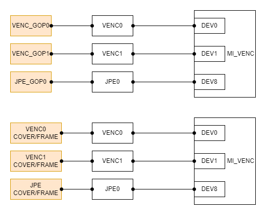
- The device0 on the VENC exclusively occupy the VENC_GOP0 and VENC_COVER/FRAME hardware, the device1 exclusively occupy the VENC_GOP1 and VENC1_COVER/FRAME hardware, the device8 exclusively occupy the JPE_GOP0 and JPE_COVER/FRAME hardware.
Table 1-21:OSD support information
| Channel type | Hardware layer count of OSD | OSD color invert | ARGB1555/ARGB4444/I2/I4/I8 | RGB565 | ARGB8888 |
|---|---|---|---|---|---|
| VENC0 | 8 | NA | Y | NA | NA |
| VENC1 | 8 | NA | Y | NA | NA |
| JPE | 8 | NA | Y | NA | NA |
- The DISP_GOP of the chip is used to display the UI to the module MI_FB.
Table 1-22:SCL MFF support information
| Channel type | Frame count | Color Cover count | Mosaic count | Line count | Polygonal Cover |
|---|---|---|---|---|---|
| SCL | NA | 4 | NA | NA | NA |
- The SCL of the chip can only attach the COVER, not support FRAME and LINE.
Table 1-23:VENC MFF support information
| Channel type | Frame+Color Cover+Line count | Mosaic count | Polygonal Cover |
|---|---|---|---|
| VENC0 | 32 | 32 | NA |
| VENC1 | 32 | 32 | NA |
- The layer of different types of regions on the VENC channel are OSD, MFF(Contains FRAME, color mode COVER and LINE), mosaic modeCOVER from top to bottom.
- The color modes COVER, FRAME and LINE of VENC are realized by the same hardware. On the same channel, these three RGN arecounted uniformly, the channel can paste a total of 32 regions of these three types at the same time.
- On the same channel of VENC, there can be at most 16 colors of color modes COVER, FRAME and LINE, and the same color can bereused.
- The color mode of VENC, the levels of COVER, FRAME and LINE are determined by the u32Layer parameter, and the level of theregion with higher value must be above the region with lower value.
Table 1-24:JPE MFF support information
| Channel type | Frame count | Color Cover+Mosaic count | Line count | Polygonal Cover |
|---|---|---|---|---|
| JPE | 32 | 64 | NA | NA |
- The layer of different types of regions on the JPE channel are OSD, FRAME, COVER(Contains color mode COVER and mosaic modecover) from top to bottom.
- JPE color mode COVER and MOSAIC are realized by the same hardware. On the same channel, these two RGN are counted uniformly, thechannel can paste a total of 64 areas of these two types at the same time.
- JPE on the same channel, there can only be 16 colors for the color modes COVER and FRAME, and the same color can be reused.
Table 1-25:The support situation of mosaic mode block size
| Channel type | block size 4 | block size 8 | block size 16 | block size 32 | block size 64 | block size 128 | block size 256 |
|---|---|---|---|---|---|---|---|
| VENC0 | Y | Y | Y | Y | N | N | N |
| VENC1 | Y | Y | Y | Y | N | N | N |
| JPE | Y | Y | Y | Y | N | N | N |
1.5.14 Ifliegen
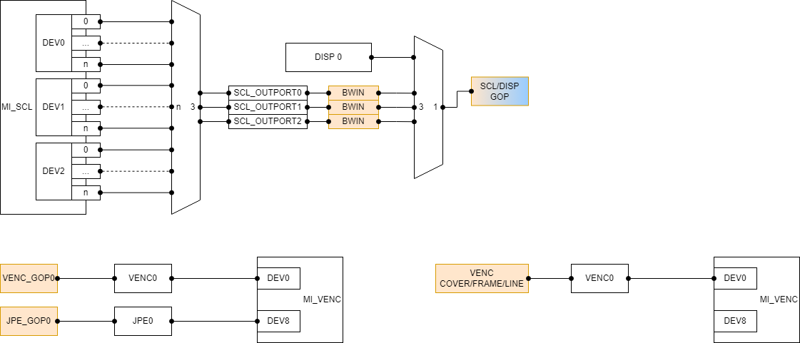
Table 1-26:OSD support information
| Channel type | Hardware layer count of OSD | OSD color invert | ARGB1555/ARGB4444/I2/I4 | I8 | RGB565 | ARGB8888 |
|---|---|---|---|---|---|---|
| SCL_OUTPUT_PORT | 1 | NA | Y | Y | Y | Y |
| VENC0 | 4 | NA | Y | NA | NA | NA |
| JPE | 4 | NA | Y | Y | NA | NA |
- SCL GOP will be reuesd by multiple SCL hardware, please refer to Table 1-4: RGN's hardware reuse rules.
Table 1-27:SCL MFF support information
| Channel type | Frame count | Color Cover count | Mosaic count | Line count | Polygonal Cover |
|---|---|---|---|---|---|
| SCL_OUTPUT_PORT | NA | 4 | NA | NA | NA |
Table 1-28:VENC&JPE MFF support information
| Channel type | Frame+Color Cover+Line count | Mosaic count | Polygonal Cover |
|---|---|---|---|
| VENC0 | 16 | NA | NA |
| JPE | NA | NA | NA |
- The layer of different types of regions on the VENC channel are OSD, MFF(Contains FRAME, color mode COVER and LINE).
- The color modes COVER, FRAME and LINE of VENC are realized by the same hardware. On the same channel, these three RGN arecounted uniformly, the channel can paste a total of 16 regions of these three types at the same time.
- On the same channel of VENC, there can be at most 16 colors of color modes COVER, FRAME and LINE, and the same color can bereused.
- The color mode of VENC, the levels of COVER, FRAME and LINE are determined by the u32Layer parameter, and the level of theregion with higher value must be above the region with lower value.
- JPE channel does not support attach any region.
1.5.15 Ihalo
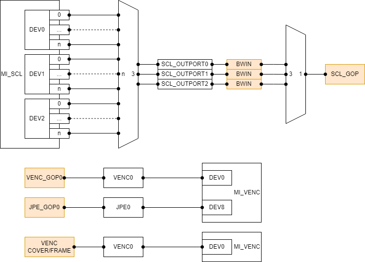
Table 1-29:OSD support information
| Channel type | Hardware layer count of OSD | OSD color invert | ARGB1555/ARGB4444/I2/I4 | I8 | RGB565 | ARGB8888 |
|---|---|---|---|---|---|---|
| SCL_OUTPUT_PORT | 1 | NA | Y | Y | Y | Y |
| VENC0 | 4 | NA | Y | NA | NA | NA |
| JPE | 4 | NA | Y | Y | NA | NA |
- SCL GOP will be reuesd by multiple SCL hardware, please refer to Table 1-4: RGN's hardware reuse rules.
Table 1-30:SCL MFF support information
| Channel type | Frame count | Color Cover count | Mosaic count | Line count | Polygonal Cover |
|---|---|---|---|---|---|
| SCL_OUTPUT_PORT | NA | 4 | NA | NA | NA |
Table 1-31:VENC&JPE MFF support information
| Channel type | Frame+Color Cover+Line count | Mosaic count | Polygonal Cover |
|---|---|---|---|
| VENC0 | 16 | 32 | NA |
| JPE | NA | NA | NA |
- The layer of different types of regions on the VENC channel are OSD, MFF(Contains FRAME, color mode COVER, mosaic mode COVER and LINE).
- The color modes COVER, FRAME and LINE of VENC are realized by the same hardware. On the same channel, these three RGN arecounted uniformly, the channel can paste a total of 16 regions of these three types at the same time.
- On the same channel of VENC, there can be at most 16 colors of color modes COVER, FRAME and LINE, and the same color can bereused.
- The color mode of VENC, the levels of COVER, FRAME and LINE are determined by the u32Layer parameter, and the level of theregion with higher value must be above the region with lower value.
- JPE channel does not support attach any region.
Table 1-32:The support situation of mosaic mode block size
| Channel type | block size 4 | block size 8 | block size 16 | block size 32 | block size 64 | block size 128 | blocksize 256 |
|---|---|---|---|---|---|---|---|
| VENC | Y | Y | Y | Y | N | N | N |
1.5.16 Mhera
- This chip RGN can only attach the COVER on SCL.
- Each SCL output port corresponds to a COVER hardware. Different COVER hardware is independent of each other and can be used at the same time.
Table 1-33: Chip information of Mhera
| Channel type | Hardware layer count of OSD | OSD color invert | Frame count | Cover count | Mosaic mode | Polygonal Cover | ARGB1555/ARGB4444/I2/I4/I8 | ARGB8888/RGB565 |
|---|---|---|---|---|---|---|---|---|
| SCL_OUTPUT_PORT | NA | NA | NA | 4 | NA | NA | NA | NA |
1.6. Principle
Different types of regions correspond to distinct hardware for management. MI_RGN use GOP to manage OSD, use MFF to manage COVER, FRAME and LINE. SCL_OUTPUT_PORT attach COVER is used by hardware BWIN on some chip.
1.7. Development Process
-
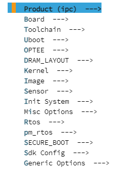
Enter alkaid project root directory, make menuconfig
-
Press Enter to enter the Generic Options sub-option

-
Press Enter to enter the Interface Compile Config sub-option

-
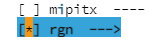
Press Space bar to select the rgn module
-
Press Enter to enter the fb module, select the sub-option supported by the chip and recompile the project
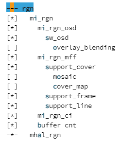
After compilation, mi_rgn.ko will generated in project/release, and release mi_rgn.h and mi_rgn_datatype.h to this directory at the same time. It will be packaged into images by default in pure Linux.
1.8. Example
1.8.1 RGN attch the osd on SCL
#include <string.h>
#include <stdio.h>
#include "mi_sys.h"
#include "mi_rgn.h"
#include "mi_rgn_datatype.h"

#define OSD_WIDTH (100)
#define OSD_HEIGHT (100)
#define MAX_CANVAS_NUM (3)
#define FILE_PATH "/mnt/demo_100x100.argb1555.yuv"
#define YUV_STRIDE (200)

int main()
{
    MI_SYS_Init(0);
    MI_S32 s32Ret = 0;
    MI_RGN_PaletteTable_t stPaletteTable;
    MI_RGN_HANDLE hHandle = 0;
    MI_RGN_Attr_t stRegion;
    MI_RGN_ChnPort_t stChnPort;
    MI_RGN_ChnPortParam_t stChnAttr;
    MI_RGN_CanvasInfo_t stCanvasInfo;
    MI_S32 s32ReadCnt = 0;
    FILE *file = NULL;

    memset(&stPaletteTable, 0, sizeof(MI_RGN_PaletteTable_t));
    stPaletteTable.astElement[1].u8Alpha = 255;
    stPaletteTable.astElement[1].u8Red = 255;
    stPaletteTable.astElement[1].u8Green = 0;
    stPaletteTable.astElement[1].u8Blue = 0;
    // ... ...
    stPaletteTable.astElement[255].u8Alpha = 255;
    stPaletteTable.astElement[255].u8Red = 128;
    stPaletteTable.astElement[255].u8Green = 128;
    stPaletteTable.astElement[255].u8Blue = 128;
    s32Ret = MI_RGN_Init(0, &stPaletteTable);

    memset(&stRegion, 0, sizeof(MI_RGN_Attr_t));
    stRegion.eType = E_MI_RGN_TYPE_OSD;
    stRegion.stOsdInitParam.ePixelFmt = E_MI_RGN_PIXEL_FORMAT_ARGB1555;
    stRegion.stOsdInitParam.stSize.u32Width = OSD_WIDTH;
    stRegion.stOsdInitParam.stSize.u32Height = OSD_WIDTH;
    stRegion.stOsdInitParam.u16MaxCanvasNum = MAX_CANVAS_NUM;
    s32Ret = MI_RGN_Create(0, hHandle, &stRegion);
    if (s32Ret != MI_RGN_OK)
    {
        return s32Ret;
    }

    memset(&stChnPort, 0, sizeof(MI_RGN_ChnPort_t));
    memset(&stChnAttr, 0, sizeof(MI_RGN_ChnPortParam_t));
    stChnPort.eModId = E_MI_MODULE_ID_SCL;
    stChnPort.s32DevId = 0;
    stChnPort.s32ChnId = 0;
    stChnPort.s32PortId = 0;
    stChnPort.bInputPort = FALSE;
    stChnAttr.bShow = TRUE;
    stChnAttr.u32Layer = 0;
    stChnAttr.stOsdChnPort.stPoint.s32X = 100;
    stChnAttr.stOsdChnPort.stPoint.s32Y = 100;
    stChnAttr.stOsdChnPort.stOsdAlphaAttr.eAlphaMode = E_MI_RGN_PIXEL_ALPHA;
    stChnAttr.stOsdChnPort.stOsdAlphaAttr.stAlphaPara.stArgb1555Alpha.u8BgAlpha = 0;
    stChnAttr.stOsdChnPort.stOsdAlphaAttr.stAlphaPara.stArgb1555Alpha.u8FgAlpha = 0xff;
    s32Ret = MI_RGN_AttachToChn(0, hHandle, &stChnPort, &stChnAttr);
    if (s32Ret != MI_RGN_OK)
    {
        return s32Ret;
    }

    // get canvas
    memset(&stCanvasInfo,0,sizeof(MI_RGN_CanvasInfo_t));
    s32Ret = MI_RGN_GetCanvasInfo(0, hHandle, &stCanvasInfo);
    if (s32Ret != MI_RGN_OK)
    {
        return s32Ret;
    }

    // read yuv file
    // please modify FILE_PATH and YUV_STRIDE first
    file = fopen(FILE_PATH,"rb");
    for (int i = 0; i < stCanvasInfo.stSize.u32Height ; i++)
    {
       fseek(file, YUV_STRIDE, SEEK_SET);
       s32ReadCnt += fread((MI_U8*)stCanvasInfo.virtAddr + i * stCanvasInfo.u32Stride, 1, YUV_STRIDE, file);
    }
    fclose(file);

    // update canvas
    s32Ret = MI_RGN_UpdateCanvas(0, hHandle);
    if (s32Ret != MI_RGN_OK)
    {
        return s32Ret;
    }

    s32Ret = MI_RGN_DetachFromChn(0, hHandle, &stChnPort);
    if (s32Ret != MI_RGN_OK)
    {
        return s32Ret;
    }

    s32Ret = MI_RGN_Destroy(0, hHandle);
    if (s32Ret != MI_RGN_OK)
    {
        return s32Ret;
    }

    s32Ret = MI_RGN_DeInit(0);
    if (s32Ret != MI_RGN_OK)
    {
        return s32Ret;
    }

    MI_SYS_Exit(0);
    return 0;
}
1.8.2 RGN attch the cover on SCL
#include <string.h>
#include "mi_sys.h"
#include "mi_rgn.h"
#include "mi_rgn_datatype.h"

int main()
{
    MI_SYS_Init(0);
    MI_S32 s32Ret = 0;
    MI_RGN_PaletteTable_t stPaletteTable;
    MI_RGN_HANDLE hHandle = 0;
    MI_RGN_Attr_t stRegion;
    MI_RGN_ChnPort_t stChnPort;
    MI_RGN_ChnPortParam_t stChnAttr;

    memset(&stPaletteTable, 0, sizeof(MI_RGN_PaletteTable_t));
    stPaletteTable.astElement[1].u8Alpha = 255;
    stPaletteTable.astElement[1].u8Red = 255;
    stPaletteTable.astElement[1].u8Green = 0;
    stPaletteTable.astElement[1].u8Blue = 0;
    // ... ...
    stPaletteTable.astElement[255].u8Alpha = 255;
    stPaletteTable.astElement[255].u8Red = 128;
    stPaletteTable.astElement[255].u8Green = 128;
    stPaletteTable.astElement[255].u8Blue = 128;
    s32Ret = MI_RGN_Init(0, &stPaletteTable);

    memset(&stRegion, 0, sizeof(MI_RGN_Attr_t));
    stRegion.eType = E_MI_RGN_TYPE_COVER;
    s32Ret = MI_RGN_Create(0, hHandle, &stRegion);
    if (s32Ret != MI_RGN_OK)
    {
        return s32Ret;
    }

    memset(&stChnPort, 0, sizeof(MI_RGN_ChnPort_t));
    memset(&stChnAttr, 0, sizeof(MI_RGN_ChnPortParam_t));
    stChnPort.eModId = E_MI_MODULE_ID_SCL;
    stChnPort.s32DevId = 0;
    stChnPort.s32ChnId = 0;
    stChnPort.s32PortId = 0;
    stChnPort.bInputPort = FALSE;
    stChnAttr.bShow = TRUE;
    stChnAttr.u32Layer = 0;

    // rect cover
    stChnAttr.stCoverChnPort.eAreaType = E_MI_RGN_AREA_TYPE_RECT;
    stChnAttr.stCoverChnPort.stRect.s32X = 0;
    stChnAttr.stCoverChnPort.stRect.s32Y = 0;
    stChnAttr.stCoverChnPort.stRect.u32Width = 1024;
    stChnAttr.stCoverChnPort.stRect.u32Height = 1024;
    // color mode
    stChnAttr.stCoverChnPort.eMode = E_MI_RGN_COVER_MODE_COLOR;
    stChnAttr.stCoverChnPort.stColorAttr.u32Color = 0xff0000;
    /* mosaic mode
    stChnAttr.stCoverChnPort.eMode = E_MI_RGN_COVER_MODE_MOSAIC;
    stChnAttr.stCoverChnPort.stMosaicAttr.eBlkSize = E_MI_RGN_BLOCK_SIZE_64;
    */
    s32Ret = MI_RGN_AttachToChn(0, hHandle, &stChnPort, &stChnAttr);
    if (s32Ret != MI_RGN_OK)
    {
        return s32Ret;
    }

    /* poly cover
    memset(&stChnAttr, 0, sizeof(MI_RGN_ChnPortParam_t));
    stChnAttr.stCoverChnPort.eAreaType = E_MI_RGN_AREA_TYPE_POLY;
    stChnAttr.stCoverChnPort.stPoly.u8VertexNum = 6;
    stChnAttr.stCoverChnPort.stPoly.astCoord[0].s32X = 1024;
    stChnAttr.stCoverChnPort.stPoly.astCoord[0].s32Y = 0;
    stChnAttr.stCoverChnPort.stPoly.astCoord[1].s32X = 2048;
    stChnAttr.stCoverChnPort.stPoly.astCoord[1].s32Y = 0;
    stChnAttr.stCoverChnPort.stPoly.astCoord[2].s32X = 3072;
    stChnAttr.stCoverChnPort.stPoly.astCoord[2].s32Y = 1024;
    stChnAttr.stCoverChnPort.stPoly.astCoord[3].s32X = 2048;
    stChnAttr.stCoverChnPort.stPoly.astCoord[3].s32Y = 2048;
    stChnAttr.stCoverChnPort.stPoly.astCoord[4].s32X = 1024;
    stChnAttr.stCoverChnPort.stPoly.astCoord[4].s32Y = 2048;
    stChnAttr.stCoverChnPort.stPoly.astCoord[5].s32X = 0;
    stChnAttr.stCoverChnPort.stPoly.astCoord[5].s32Y = 1024;
    s32Ret = MI_RGN_AttachToChn(0, hHandle, &stChnPort, &stChnAttr);
    if (s32Ret != MI_RGN_OK)
    {
        return s32Ret;
    }
    */

    s32Ret = MI_RGN_DetachFromChn(0, hHandle, &stChnPort);
    if (s32Ret != MI_RGN_OK)
    {
        return s32Ret;
    }

    s32Ret = MI_RGN_Destroy(0, hHandle);
    if (s32Ret != MI_RGN_OK)
    {
        return s32Ret;
    }

    s32Ret = MI_RGN_DeInit(0);
    if (s32Ret != MI_RGN_OK)
    {
        return s32Ret;
    }

    MI_SYS_Exit(0);
    return 0;
}
1.8.3 RGN attch the frame on SCL
#include <string.h>
#include "mi_sys.h"
#include "mi_rgn.h"
#include "mi_rgn_datatype.h"

int main()
{
    MI_SYS_Init(0);
    MI_S32 s32Ret = 0;
    MI_RGN_PaletteTable_t stPaletteTable;
    MI_RGN_HANDLE hHandle = 0;
    MI_RGN_Attr_t stRegion;
    MI_RGN_ChnPort_t stChnPort;
    MI_RGN_ChnPortParam_t stChnAttr;

    memset(&stPaletteTable, 0, sizeof(MI_RGN_PaletteTable_t));
    stPaletteTable.astElement[1].u8Alpha = 255;
    stPaletteTable.astElement[1].u8Red = 255;
    stPaletteTable.astElement[1].u8Green = 0;
    stPaletteTable.astElement[1].u8Blue = 0;
    // ... ...
    stPaletteTable.astElement[255].u8Alpha = 255;
    stPaletteTable.astElement[255].u8Red = 128;
    stPaletteTable.astElement[255].u8Green = 128;
    stPaletteTable.astElement[255].u8Blue = 128;
    s32Ret = MI_RGN_Init(0, &stPaletteTable);

    memset(&stRegion, 0, sizeof(MI_RGN_Attr_t));
    stRegion.eType = E_MI_RGN_TYPE_COVER;
    s32Ret = MI_RGN_Create(0, hHandle, &stRegion);
    if (s32Ret != MI_RGN_OK)
    {
        return s32Ret;
    }

    memset(&stChnPort, 0, sizeof(MI_RGN_ChnPort_t));
    memset(&stChnAttr, 0, sizeof(MI_RGN_ChnPortParam_t));
    stChnPort.eModId = E_MI_MODULE_ID_SCL;
    stChnPort.s32DevId = 0;
    stChnPort.s32ChnId = 0;
    stChnPort.s32PortId = 0;
    stChnPort.bInputPort = FALSE;
    stChnAttr.bShow = TRUE;
    stChnAttr.u32Layer = 0;
    stChnAttr.stFrameChnPort.u32Color = 0xff0000;
    stChnAttr.stFrameChnPort.stRect.s32X = 100;
    stChnAttr.stFrameChnPort.stRect.s32Y = 100;
    stChnAttr.stFrameChnPort.stRect.u32Width = 100;
    stChnAttr.stFrameChnPort.stRect.u32Height = 100;
    stChnAttr.stFrameChnPort.u8Thickness = 5;

    s32Ret = MI_RGN_AttachToChn(0, hHandle, &stChnPort, &stChnAttr);
    if (s32Ret != MI_RGN_OK)
    {
        return s32Ret;
    }

    s32Ret = MI_RGN_DetachFromChn(0, hHandle, &stChnPort);
    if (s32Ret != MI_RGN_OK)
    {
        return s32Ret;
    }

    s32Ret = MI_RGN_Destroy(0, hHandle);
    if (s32Ret != MI_RGN_OK)
    {
        return s32Ret;
    }

    s32Ret = MI_RGN_DeInit(0);
    if (s32Ret != MI_RGN_OK)
    {
        return s32Ret;
    }

    MI_SYS_Exit(0);
    return 0;
}
1.8.4 RGN attch the line on SCL
#include <string.h>
#include "mi_sys.h"
#include "mi_rgn.h"
#include "mi_rgn_datatype.h"

int main()
{
    MI_SYS_Init(0);
    MI_S32 s32Result = 0;
    MI_RGN_PaletteTable_t stPaletteTable;
    MI_RGN_HANDLE hHandle = 0;
    MI_RGN_Attr_t stRegion;
    MI_RGN_ChnPort_t stChnPort;
    MI_RGN_ChnPortParam_t stChnAttr;

    memset(&stPaletteTable, 0, sizeof(MI_RGN_PaletteTable_t));
    stPaletteTable.astElement[1].u8Alpha = 255;
    stPaletteTable.astElement[1].u8Red = 255;
    stPaletteTable.astElement[1].u8Green = 0;
    stPaletteTable.astElement[1].u8Blue = 0;
    // ... ...
    stPaletteTable.astElement[255].u8Alpha = 255;
    stPaletteTable.astElement[255].u8Red = 128;
    stPaletteTable.astElement[255].u8Green = 128;
    stPaletteTable.astElement[255].u8Blue = 128;
    s32Result = MI_RGN_Init(0, &stPaletteTable);

    memset(&stRegion, 0, sizeof(MI_RGN_Attr_t));
    stRegion.eType = E_MI_RGN_TYPE_COVER;
    s32Result = MI_RGN_Create(0, hHandle, &stRegion);
    if (s32Result != MI_RGN_OK)
    {
        return s32Result;
    }

    memset(&stChnPort, 0, sizeof(MI_RGN_ChnPort_t));
    memset(&stChnAttr, 0, sizeof(MI_RGN_ChnPortParam_t));
    stChnPort.eModId = E_MI_MODULE_ID_SCL;
    stChnPort.s32DevId = 0;
    stChnPort.s32ChnId = 0;
    stChnPort.s32PortId = 0;
    stChnPort.bInputPort = FALSE;
    stChnAttr.bShow = TRUE;
    stChnAttr.u32Layer = 0;
    stChnAttr.stLineChnPort.stPointFrom.s32X = 100;
    stChnAttr.stLineChnPort.stPointFrom.s32Y = 100;
    stChnAttr.stLineChnPort.stPointTo.s32X = 200;
    stChnAttr.stLineChnPort.stPointTo.s32Y = 200;
    stChnAttr.stLineChnPort.u32LineWidth = 5;
    stChnAttr.stLineChnPort.u32Color = 0xff0000;
    stChnAttr.stLineChnPort.bHollow = FALSE;
    stChnAttr.stLineChnPort.u8BorderThickness = 2;
    s32Result = MI_RGN_AttachToChn(0, hHandle, &stChnPort, &stChnAttr);
    if (s32Result != MI_RGN_OK)
    {
        return s32Result;
    }

    s32Result = MI_RGN_DetachFromChn(0, hHandle, &stChnPort);
    if (s32Result != MI_RGN_OK)
    {
        return s32Result;
    }

    s32Result = MI_RGN_Destroy(0, hHandle);
    if (s32Result != MI_RGN_OK)
    {
        return s32Result;
    }

    s32Result = MI_RGN_DeInit(0);
    if (s32Result != MI_RGN_OK)
    {
        return s32Result;
    }

    MI_SYS_Exit(0);
    return 0;
}
2. API LIST
| API | Function |
|---|---|
| MI_RGN_Init | Initialization |
| MI_RGN_DeInit | De-initialization |
| MI_RGN_Create | Create region |
| MI_RGN_Destroy | Destroy region |
| MI_RGN_GetAttr | Get region attributes |
| MI_RGN_SetBitMap | Set bitmap region |
| MI_RGN_AttachToChn | Attach region to channel |
| MI_RGN_DetachFromChn | Detach region from channel |
| MI_RGN_SetDisplayAttr | Set display attributes of region |
| MI_RGN_GetDisplayAttr | Get display attributes of region |
| MI_RGN_GetCanvasInfo | Get canvas information of region |
| MI_RGN_UpdateCanvas | Update canvas information of region |
| MI_RGN_SetColorInvertAttr | Set color invert attributes of channel |
| MI_RGN_GetColorInvertAttr | Get color invert attributes of channel |
| MI_RGN_GetLuma | Get luminance information of channel |
2.1. MI_RGN_Init
-
Function
Initialization.
-
Syntax
MI_S32 MI_RGN_Init(MI_U16 u16SocId, MI_RGN_PaletteTable_t *pstPaletteTable); -
Parameters
Parameter Description Input / Output s32SocId Chip ID for multiple chips Input pstPaletteTable Pointer to the palette table Input -
Return Value
- MI_RGN_OK: Successful
- MI_ERR_RGN_BUSY: Failed. Device is initializad already. The reason for this error is that the parameters of multiple API calls are inconsistent in the branch that supports multiple processes.
-
Requirement
- Header file: mi_sys.h, mi_rgn.h.
- Library file
-
Note
-
The palette table can only be done once during initialization and cannot be set again.
-
It is not used for RGB color format.
-
The index of ‘0’ in palette array is used for colorkey, which will not display anything.
-
-
Example
MI_S32 s32Result = 0; MI_RGN_PaletteTable_t stPaletteTable; memset(&stPaletteTable, 0, sizeof(MI_RGN_PaletteTable_t)); stPaletteTable.astElement[1].u8Alpha = 255; stPaletteTable.astElement[1].u8Red = 255; stPaletteTable.astElement[1].u8Green = 0; stPaletteTable.astElement[1].u8Blue = 0; stPaletteTable.astElement[2].u8Alpha = 255; stPaletteTable.astElement[2].u8Red = 0; stPaletteTable.astElement[2].u8Green = 255; stPaletteTable.astElement[2].u8Blue = 0; stPaletteTable.astElement[3].u8Alpha = 255; stPaletteTable.astElement[3].u8Red = 0; stPaletteTable.astElement[3].u8Green = 0; stPaletteTable.astElement[3].u8Blue = 255; ... ... stPaletteTable.astElement[255].u8Alpha = 255; stPaletteTable.astElement[255].u8Red = 128; stPaletteTable.astElement[255].u8Green = 128; stPaletteTable.astElement[255].u8Blue = 128; s32Result = MI_RGN_Init(0, &stPaletteTable); s32Result = MI_RGN_DeInit(0); -
Related APIs
2.2. MI_RGN_DeInit
-
Function
De-initialization
-
Syntax
MI_S32 MI_RGN_DeInit(MI_U16 u16SocId); -
Return Value
- MI_RGN_OK: Successful
- MI_ERR_RGN_BUSY: Failed
-
Requirement
- Header file: mi_sys.h, mi_rgn.h.
- Library file
-
Example
Refer to MI_RGN_Init
-
Related APIs
2.3. MI_RGN_Create
-
Function
Create region
-
Syntax
MI_S32 MI_RGN_Create(MI_U16 u16SocId, MI_RGN_HANDLE hHandle, MI_RGN_Attr_t *pstRegion); -
Parameters
Parameter Description Input / Output s32SocId Chip ID for multiple chips Input hHandle Handle of region. Must be an unused hHandle
Range: [0, MI_RGN_MAX_HANDLE).Input pstRegion Pointer to the attribute of region Input -
Return Value
- MI_RGN_OK: Successful
- Not MI_RGN_OK: Failed. Please refer to Return Value
-
Requirement
- Header file: mi_sys.h, mi_rgn.h.
- Library file
-
Note
- This handle is specified by the user and has the same meaning as the ID.
- Repeated creation is not supported.
- The attribute of region must be legal, please refer to MI_RGN_Attr_t.
- OSD, COVER, FRAME or LINE is specified in MI_RGN_Attr_t.
- The pointer to attribute of region cannot be null.
- When creating a COVER, FRAME or LINE, it only needs to assign the region type. Other attributes, such as location, hierarchy, etc., are assigned when the MI_RGN_AttachToChn interface is called.
- When creating a region, this only checks the basic parameters such as minimum width and height, maximum width and height. When this region is attached to the channel, more targeted parameters can be checked based on constraints of the supported type of channel module. Such as supported pixel formats, etc.
- This interface allows you to set the maximum number of buffers used by each OSD node and assign u16MaxCanvasNum in the structure MI_RGN_Attr_t.
- If u16MaxCanvasNum is set to 1, it indicates that risk of screen tearing is allowed and accepted, and no error messages will be printed.
-
Example
MI_S32 s32Result = 0; MI_RGN_HANDLE hHandle = 0; MI_RGN_Attr_t stRegion; stRegion.eType = E_MI_RGN_TYPE_OSD; stRegion.stOsdInitParam.ePixelFmt = E_MI_RGN_PIXEL_FORMAT_ARGB1555; stRegion.stOsdInitParam.stSize.u32Width = 40; stRegion.stOsdInitParam.stSize.u32Height = 40; stRegion.stOsdInitParam.u16MaxCanvasNum = 3; s32Result = MI_RGN_Create(0, hHandle, &stRegion); if (s32Result != MI_RGN_OK) { return s32Result; } s32Result = MI_RGN_GetAttr(0, hHandle, &stRegion); if (s32Result != MI_RGN_OK) { return s32Result; } s32Result = MI_RGN_Destroy(0, hHandle); if (s32Result != MI_RGN_OK) { return s32Result; } -
Related APIs
2.4. MI_RGN_Destroy
-
Function
Destroy region
-
Syntax
MI_S32 MI_REG_Destroy (MI_U16 u16SocId, MI_RGN_HANDLE hHandle); -
Parameters
Parameter Description Input / Output s32SocId Chip ID for multiple chips Input hHandle Handle of region.
Range: [0, MI_RGN_MAX_HANDLE).Input -
Return Value
- MI_RGN_OK: Successful
- Not MI_RGN_OK: Failed. Please refer to Return Value
-
Requirement
- Header file: mi_sys.h, mi_rgn.h.
- Library file:
-
Note
Region must have been created.
-
Example
Refer to MI_RGN_Create
-
Related APIs
2.5. MI_RGN_GetAttr
-
Function
Get the attribute of region.
-
Syntax
MI_S32 MI_RGN_GetAttr(MI_U16 u16SocId, MI_RGN_HANDLE hHandle, MI_RGN_Attr_t *pstRegion); -
Parameters
Parameter Description Input / Output s32SocId Chip ID for multiple chips Input hHandle Handle of region.
Range: [0, MI_RGN_MAX_HANDLE).Input pstRegion Pointer to the attribute of region. Output -
Return Value
- MI_RGN_OK: Successful
- Not MI_RGN_OK: Failed. Please refer to Return Value
-
Requirement
- Header file: mi_sys.h, mi_rgn.h.
- Library file:
-
Note
- Region must have been created.
- The pointer to the attribute of region cannot be null.
-
Example
Refer to MI_RGN_Create.
2.6. MI_RGN_SetBitMap
-
Function
Set the region bitmap, that is, fill the region with bitmap.
-
Syntax
MI_S32 MI_RGN_SetBitMap(MI_U16 u16SocId, MI_RGN_HANDLE hHandle, MI_RGN_Bitmap_t *pstBitmap); -
Parameters
Parameter Description Input / Output s32SocId Chip ID for multiple chips Input hHandle Handle of region.
Range: [0, MI_RGN_MAX_HANDLE).Input pstBitmap The pointer to the attribute of bitmap Input -
Return Value
- MI_RGN_OK: Successful
- MI_ERR_RGN_BUSY: Failed. The number of OSD buffer has reached the maximum value and all buffer were busy. Please call this API repeatedly until a buffer is free.
- Not MI_RGN_OK: Failed. Please refer to Return Value
-
Requirement
- Header file: mi_sys.h, mi_rgn.h.
- Library file:
-
Note
- Region must have been created.
- The size of the supported bitmap is inconsistent with the size of the region.
- The bitmap is loaded from (0,0) of the region. When the bitmap is larger than the region, the image will be automatically cropped into region.
- The pixel format of the bitmap must be the same as the pixel format of the region.
- The pointer to the attribute of bitmap cannot be null.
- Support multiple calls.
- This interface is only valid for overlay.
- After calling MI_RGN_GetCanvasInfo, calling this interface is invalid unless MI_RGN_UpdateCanvas is in effect.
-
Example
MI_S32 s32Result = 0;
MI_HANDLE hHandle = 0;
MI_RGN_Bitmap_t stBitmap;
MI_U32 u32FileSize = 200 * 200 * 2;
MI_U8 *pu8FileBuffer = NULL;
FILE *pFile = fopen("200X200.argb1555", "rb");
if (pFile == NULL)
{
    printf("open file failed \n");
    return -1;
}
pu8FileBuffer = (MI_U8*)malloc(u32FileSize);
if (pu8FileBuffer == NULL)
{
    printf("malloc failed fileSize=%d\n", u32FileSize);
    fclose(pFile);
    return -1;
}
memset(pu8FileBuffer, 0, u32FileSize);
fread(pu8FileBuffer, 1,  u32FileSize, pFile);
fclose(pFile);
stBitmap.stSize.u32Width = 200;
stBitmap.stSize.u32Height = 200;
stBitmap.ePixelFormat = E_MI_RGN_PIXEL_FORMAT_ARGB1555;
stBitmap.pData = pu8FileBuffer;
s32Result = MI_RGN_SetBitMap(0, hHandle, &stBitmap);
free(pu8FileBuffer);
2.7. MI_RGN_AttachToChn
-
Function
Attach region to channel
-
Syntax
MI_S32 MI_RGN_AttachToChn(MI_U16 u16SocId, MI_RGN_HANDLE hHandle, MI_RGN_ChnPort_t* pstChnPort, MI_RGN_ChnPortParam_t *pstChnAttr); -
Parameters
Parameter Description Input / Output s32SocId Chip ID for multiple chips Input hHandle Handle of region.
Range: [0, MI_RGN_MAX_HANDLE).Input pstChnPort Pointer to channel port When region type is Cover and the output port is VPE, only port 0 and port 3 are valid. Input pstChnAttr Pointer to the attribute of channel port. Input -
Return Value
- MI_RGN_OK: Successful
- Not MI_RGN_OK: Failed. Please refer to Return Value
-
Requirement
- Header file: mi_sys.h, mi_rgn.h.
- Library file:
-
Note
- Region must have been created.
- Pointer to channel port cannot be null.
- Pointer to the attribute of channel port cannot be null.
- Different RGN types use different channel parameters to set channel properties:
- OSD : MI_RGN_OsdChnPortParam_t
- COVER: MI_RGN_CoverChnPortParam_t
- FRAME: MI_RGN_FrameChnPortParam_t
- LINE : MI_RGN_LineChnPortParam_t
- Not all channels have the ability to overlay regions.
- COVER, FRAME and LINE can only be worked by hardware layer. OSD can be worked by software layer, which is implemented by software merge. The pixel format of OSD merge into an same buffer must be same.
- The channel id does not have any limitation about OSD, FRAME, COVER and LINE attached on the channel.
- The RGN is not supported when SCL used rotate function.
- If the OSD attached on the channel is less than or equal to the number of hardware layers, all the hardware layers will be used, otherwise, the software jigsaw will be used.
- SCL corresponds to MI_SCL module, it usually bind hardware of SCL and software of device id / port id when initializing. For more information, please refer to MI SCL API document.
- DISP corresponds to MI_DISP module. The DISPx in the table is bound to the device id of the MI_DISP module, and only the device id can be set. Channel id and Port id need to be filled with 0(bInputPort invalid).
- JPE and VENC correspond to different devices of the MI_VENC module (Please refer to MI VENC API for details). The channel id is filled in according to the actual situation, and the port id corresponds to the port id of MI_VENC(bInputPort invalid).
-
Example
MI_S32 s32Result = 0; MI_RGN_HANDLE hHandle = 0; MI_RGN_ChnPort_t stChnPort; MI_RGN_ChnPortParam_t stChnAttr; memset(stChnPort, 0, sizeof(MI_RGN_ChnPort_t)); memset(stChnAttr, 0, sizeof(MI_RGN_ChnPortParam_t)); stChnPort.eModId = E_MI_MODULE_ID_SCL; stChnPort.s32DevId = 0; stChnPort.s32ChnId = 0; stChnPort.s32PortId = 0; stChnPort.bInputPort = FALSE; stChnAttr.bShow = TRUE; stChnAttr.u32Layer = 0; stChnAttr.stCoverChnPort.eAreaType = E_MI_RGN_AREA_TYPE_RECT; stChnAttr.stCoverChnPort.stRect.s32X = 0; stChnAttr.stCoverChnPort.stRect.s32Y = 0; stChnAttr.stCoverChnPort.stRect.u32Width = 1024; stChnAttr.stCoverChnPort.stRect.u32Height = 1024; stChnAttr.stCoverChnPort.eMode = E_MI_RGN_COVER_MODE_COLOR; stChnAttr.stCoverChnPort.u32Color = 0xffff00; s32Result = MI_RGN_AttachToChn(0, hHandle, &stChnPort, &stChnAttr); if (s32Result != MI_RGN_OK) { return s32Result; } s32Result = MI_RGN_DetachFromChn(0, hHandle, &stChnPort); if (s32Result != MI_RGN_OK) { return s32Result; } -
Related APIs
2.8. MI_RGN_DetachFromChn
-
Function
Detach region from channel
-
Syntax
MI_S32 MI_RGN_DetachFromChn(MI_U16 u16SocId, MI_RGN_HANDLE hHandle, MI_RGN_ChnPort_t *pstChnPort); -
Parameters
Parameter Description Input / Output s32SocId Chip ID for multiple chips Input hHandle Handle of region.
Range: [0, MI_RGN_MAX_HANDLE).Input pstChnPort The pointer to channel port Input -
Return Value
- MI_RGN_OK: Successful
- Not MI_RGN_OK: Failed. Please refer to Return Value
-
Requirement
- Header file: mi_sys.h, mi_rgn.h.
- Library file:
-
Note
- Region must have been created.
- The pointer to channel port cannot be null.
- The region must overlay with channel first.
-
Example
Refer to MI_RGN_AttachToChn.
-
Related APIs
2.9. MI_RGN_SetDisplayAttr
-
Function
Set the display attribute of region.
-
Syntax
MI_S32 MI_RGN_SetDisplayAttr(MI_U16 u16SocId, MI_RGN_HANDLE hHandle, MI_RGN_ChnPort_t *pstChnPort, MI_RGN_ChnPortParam_t *pstChnPortAttr); -
Parameters
Parameter Description Input / Output s32SocId Chip ID for multiple chips Input hHandle Handle of region.
Range: [0, MI_RGN_MAX_HANDLE).Input pstChnPort The pointer to channel port Input pstChnPortAttr The pointer to the parameter of channel port Input -
Return Value
- MI_RGN_OK: Successful
- Not MI_RGN_OK: Failed. Please refer to Return Value
-
Requirement
- Header file: mi_sys.h, mi_rgn.h.
- Library file:
-
Note
- Region must have been created.
- It is recommended to obtain the attributes first and then set them.
- The pointer to channel port cannot be null.
- The pointer to the parameter of channel port cannot be null.
- The region must overlay with channel first.
- Static properties cannot be modified, dynamic properties can be modified. Refer to MI_RGN_ChnPortParam_t
-
Example
MI_S32 s32Result = 0; MI_RGN_HANDLE hHandle = 0; MI_RGN_ChnPort_t stChnPort; MI_RGN_ChnPortParam_t stChnAttr; stChnPort.eModId = E_MI_MODULE_ID_SCL; stChnPort.s32DevId = 0; stChnPort.s32ChnId = 0; stChnPort.s32PortId = 0; stChnPort.bInputPort = FALSE; s32Result = MI_RGN_GetDisplayAttr(0, hHandle, &stChnPort, &stChnAttr); if (s32Result != MI_RGN_OK) { return s32Result; } stChnAttr.bShow = TRUE; stChnAttr.stCoverPara.u32Layer = 0; stChnAttr.stCoverChnPort.eAreaType = E_MI_RGN_AREA_TYPE_RECT; stChnAttr.stCoverChnPort.stRect.s32X = 0; stChnAttr.stCoverChnPort.stRect.s32Y = 0; stChnAttr.stCoverChnPort.stRect.u32Width = 1024; stChnAttr.stCoverChnPort.stRect.u32Height = 1024; stChnAttr.stCoverChnPort.eMode = E_MI_RGN_COVER_MODE_COLOR; stChnAttr.stCoverChnPort.stColorAttr.u32Color = 0xffff00; s32Result = MI_RGN_SetDisplayAttr(0, hHandle, &stChnPort, &stChnAttr); if (s32Result != MI_RGN_OK) { return s32Result; } -
Related APIs
2.10. MI_RGN_GetDisplayAttr
-
Function
Get the display attribute of region.
-
Syntax
MI_S32 MI_RGN_GetDisplayAttr(MI_U16 u16SocId, MI_RGN_HANDLE hHandle, MI_RGN_ChnPort_t *pstChnPort, MI_RGN_ChnPortParam_t *pstChnPortAttr); -
Parameters
Parameter Description Input / Output s32SocId Chip ID for multiple chips Input hHandle Handle of region.
Range: [0, MI_RGN_MAX_HANDLE).Input pstChnPort The pointer to channel port Input pstChnPortAttr The pointer to the parameter of channel port Output -
Return Value
- MI_RGN_OK: Successful
- Not MI_RGN_OK: Failed. Please refer to Return Value
-
Requirement
- Header file: mi_sys.h, mi_rgn.h.
- Library file:
-
Note
- Region must have been created.
- The pointer to channel port cannot be null.
- The pointer to the parameter of channel port cannot be null.
-
Example
Refer to MI_RGN_SetDisplayAttr.
-
Related APIs
2.11. MI_RGN_GetCanvasInfo
-
Function
Get the canvas information of region.
-
Syntax
MI_S32 MI_RGN_GetCanvasInfo(MI_U16 u16SocId, MI_RGN_HANDLE hHandle, MI_RGN_CanvasInfo_t* pstCanvasInfo); -
Parameters
Parameter Description Input / Output s32SocId Chip ID for multiple chips Input hHandle Handle of region.
Range: [0, MI_RGN_MAX_HANDLE).Input pstCanvasInfo Pointer to the canvas information of region Output -
Return Value
- MI_RGN_OK: Successful
- MI_ERR_RGN_BUSY: Failed. The maximum number of canvas buffers set in the MI_RGN_Create interface is small, and all canvas buffers are occupied by hardware. In order to avoid screen tearing, you can select to call this interface repeatedly until hardware to abandon buffer. Or set u16MaxCanvasNum to a higher value when calling MI_RGN_Create.
- MI_ERR_RGN_EXIST: Failed. OSD combined in this channel and other OSD have got canvas already.
- Not MI_RGN_OK: Failed. Please refer to Return Value
-
Requirement
- Header file: mi_sys.h, mi_rgn.h.
- Library file:
-
Note
-
Region must have been created.
-
This interface is similar to MI_RGN_SetBitMap and is mainly used for overlay types to import bitmap data. This interface is relative to MI_RGN_SetBitMap, users can update directly to display the internal data of canvas, which can save one memory copy and one memory’s allocation.
- This interface is used to obtain canvas information corresponding to a region. After getting the canvas address, the user can directly operate the canvas. For example: Fill bmp data directly into the canvas, then update the display canvas data by calling MI_RGN_UpdateCanvas.
- This interface is mutually exclusive with MI_RGN_SetBitMap. If this interface is already in use, calling MI_RGN_SetBitMap does not take effect until MI_RGN_UpdateCanvas is called.
- If the channel has OSD combined, MI_RGN only allows one OSD to get canvas until this OSD call MI_RGN_UpdateCanvas. Other OSD call MI_RGN_SetBitMap and MI_RGN_GetCanvasInfo will return failed.
-
-
Example
MI_S32 s32Result = MI_RGN_OK; MI_RGN_HANDLE hHandle; MI_RGN_Attr_t stRegion; MI_RGN_CanvasInfo_t stCanvasInfo; hHandle = 10; stRegion.eType = E_MI_RGN_TYPE_OSD; stRegion.stOsdInitParam.ePixelFmt = E_MI_RGN_PIXEL_FORMAT_ARGB1555; stRegion.stOsdInitParam.stSize.u32Width = 100; stRegion.stOsdInitParam.stSize.u32Height = 100; stRegion.stOsdInitParam.u16MaxCanvasNum = 3; if (MI_RGN_OK != MI_RGN_Create(0, hHandle, &stRegion)) { printf("Create handle error!\n"); return -1; } FILE *pFile = fopen("100X100.argb1555", "rb"); if (pFile == NULL) { printf("open file failed \n"); MI_RGN_Destroy(0, hHandle); return -1; } retry_get_canvas: s32Result = MI_RGN_GetCanvas(0, hHandle, &stCanvasInfo); if (s32Result != MI_RGN_OK) { if (s32Result == MI_ERR_RGN_BUSY) // every canvas has busy now { usleep(1000); // wait 1ms goto retry_get_canvas; // rery get canvas until return success } return s32Result; } for (int i = 0; i < 100; i++) { fread((MI_U8*)stCanvasInfo.virtAddr + i * stCanvasInfo.u32Stride, 1, 100 * 2, pFile); } fclose(pFile); if (MI_RGN_UpdateCanvas(0, hHandle) != MI_RGN_OK) { return s32Result; } -
Related APIs
2.12. MI_RGN_UpdateCanvas
-
Function
Update canvas. If the canvas is attached to the path, it will display on video, otherwise it will display after attach.
-
Syntax
MI_S32 MI_RGN_UpdateCanvas(MI_U16 u16SocId, MI_RGN_HANDLE hHandle); -
Parameters
Parameter Description Input / Output s32SocId Chip ID for multiple chips Input hHandle Handle of region.
Range: [0, MI_RGN_MAX_HANDLE).Input -
Return Value
- MI_RGN_OK: Successful
- MI_ERR_RGN_NOT_PERM: Failed, you must call this API after MI_RGN_GetCanvasInfo.
- Not MI_RGN_OK: Failed. Please refer to Return Value
-
Requirement
- Header file: mi_sys.h, mi_rgn.h.
- Library file:
-
Note
- Region must have been created.
- This interface is used with MI_RGN_GetCanvasInfo. It is mainly used for canvas switching display after the canvas memory data is updated.
- This interface must be called by pair with MI_RGN_GetCanvasInfo. It is used after user calls MI_RGN_GetCanvasInfo to get the pointer of canvas and the draw operation has done.
- If the channel has OSD combined, only one OSD can be allowed to get the canvas at the same time. When two or more handle have attached to the same path, and all the handles use MI_RGN_GetCanvasInfo and this interface to draw, draw operation can work normally on the same thread; If it work on different thread, it must use ‘mutex’ lock to protect, or it may cause ‘osd’ disappearance.
-
The detail note of multithreading’s ‘mutex’ lock usage is as below:
Suppose ‘handle0’ and ‘handle1’, which run on two threads, attach to the same path.
  handle0:
      T0_0 = getcanvas
      T0_1 = update
  handle1:
      T1_0 = getcanvas
      T1_1 = update
The wrong situation below is running in order of time, which is showing error log ‘‘This path has a OSD getcanvas already. One path only one OSD getcanvas if OSD count more than GWIN count.’’ when T1_0 calling MI_RGN_GetCanvasInfo.
T0_0 -\> T1_0 -\> T0_1 -\> T1_1After using ‘mutex’, it will work fine:
lock-\> T0_0 -\> T0_1 -\> unlock -\> lock -\> T1_0 -\> T1_1 -\> unlock
-
Example
Refer to MI_RGN_GetCanvasInfo.
-
Related APIs
2.13. MI_RGN_SetColorInvertAttr
-
Function
Set color invert attributes of channel.
-
Syntax
MI_S32 MI_RGN_SetColorInvertAttr(MI_U16 u16SocId, MI_RGN_ChnPort_t *pstChnPort, MI_RGN_ColorInvertAttr_t *pstColorInvertAttr); -
Parameters
Parameter Description Input / Output s32SocId Chip ID for multiple chips Input pstChnPort The pointer to channel port Input pstColorInvertAttr The pointer to the attribute of color invert Input -
Return Value
- MI_RGN_OK: Successful
- Not MI_RGN_OK: Failed. Please refer to Return Value
-
Requirement
- Header file: mi_sys.h, mi_rgn.h.
- Library file:
-
Note
- The area of color invert is the entire channel, and the entire screen is divided into blocks based on a rectangle with a width of eBlkSizeHori and a height of eBlkSizeVert. Pixels that are less than the width or height of the color invert's blocks on the right and lower sides of the screen don't participate in color invert.
- The area of color invert includes only the area of OSD.
- Color invert has two work mode:
- "AUTO" mode, the hardware determines whether the color needs to be inverted by comparing the luminance information calculated by block with the threshold set by user.
- "MANUAL" mode, the user modifies the value of the block in buffer got through API MI_RGN_GetLuma and manually selects the block that need to be inverted.
- User can control sensitivity in "AUTO" mode:
- The block need color invert if the brightness of the current frame larger than (u8ThresholdHigh / 2).
- The block don't need color invert if the brightness of the current frame less than (u8ThresholdLow / 2).
- Otherwise, the color invert of the last frame is the same as the current frame.
-
In "MANUAL" mode, each byte represents a block in the luminance information of buffer:
- bit [6:0] is obtained by shifting the average brightness of all pixels in the block to the left by one bit. bit [7] is the color invert result of this block, 1 means color invert, and 0 means no color invert.
- Users can modify the value of the byte corresponding to the specified block after getting the luminance information of buffer. 0xff means color invert.
-
Souffle
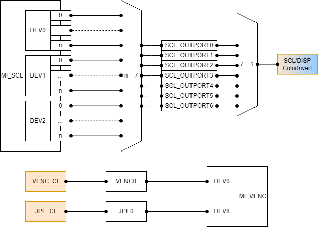
Figure 2-1: Souffle color invert related module structure diagram Channel type block size 4 block size 8 block size16 block size 32 block size 64 block size 128 block size 256 SCL_OUTPORT NA NA NA Y Y Y Y VENC NA NA NA Y Y Y Y JPE NA NA NA Y Y Y Y
-
Example
MI_S32 s32Result = MI_RGN_OK; MI_RGN_ChnPort_t stChnPort; MI_RGN_ColorInvertAttr_t stColorInvertAttr; memset(&stChnPort, 0, sizeof(MI_RGN_ChnPort_t)); memset(&stColorInvertAttr, 0, sizeof(MI_RGN_ColorInvertAttr_t)); stChnPort.eModId = E_MI_MODULE_ID_SCL; stChnPort.s32DevId = 1; stChnPort.s32ChnId = 0; stChnPort.s32PortId = 0; stChnPort.bInputPort = FALSE; stColorInvertAttr.bEnable = TRUE; stColorInvertAttr.eWorkMode = E_MI_RGN_COLOR_INVERT_WORK_MODE_AUTO; stColorInvertAttr.eBlkSizeHori = E_MI_RGN_BLOCK_SIZE_32; stColorInvertAttr.eBlkSizeVert = E_MI_RGN_BLOCK_SIZE_32; stColorInvertAttr.u8ThresholdHigh = 0x0; stColorInvertAttr.u8ThresholdLow = 0x0; s32Result = MI_RGN_SetColorInvertAttr(0, &stChnPort, &stColorInvertAttr); if (MI_RGN_OK != s32Result) { return s32Result; } s32Result = MI_RGN_GetColorInvertAttr(0, &stChnPort, &stColorInvertAttr); if (MI_RGN_OK != s32Result) { return s32Result; } -
Related APIs
2.14. MI_RGN_GetColorInvertAttr
-
Function
Get color invert attributes of channel.
-
Syntax
MI_S32 MI_RGN_GetColorInvertAttr(MI_U16 u16SocId, MI_RGN_ChnPort_t *pstChnPort, MI_RGN_ColorInvertAttr_t *pstColorInvertAttr); -
Parameters
Parameter Description Input / Output s32SocId Chip ID for multiple chips Input pstChnPort The pointer to channel port Input pstColorInvertAttr The pointer to the attribute of color invert Output -
Return Value
- MI_RGN_OK: Successful
- Not MI_RGN_OK: Failed. Please refer to Return Value
-
Requirement
- Header file: mi_sys.h, mi_rgn.h.
- Library file:
-
Note
- The pointer to channel port can't be null.
- The pointer to the attribute of color invert can't be null.
-
Example
Refer to MI_RGN_SetColorInvertAttr.
-
Related APIs
2.15. MI_RGN_GetLuma
-
Function
Get luminance information of channel.
-
Syntax
MI_S32 MI_RGN_GetLuma(MI_U16 u16SocId, MI_RGN_ChnPort_t *pstChnPort, MI_RGN_LumaInfo_t *pstLuma); -
Parameters
Parameter Description Input / Output s32SocId Chip ID for multiple chips Input pstChnPort The pointer to channel port Input pstLuma Luminance information of the channel Output -
Return Value
- MI_RGN_OK: Successful
- MI_ERR_RGN_NOBUF: Failed, this channel do not have luma buffer.
- Not MI_RGN_OK: Failed. Please refer to Return Value
-
Requirement
- Header file: mi_sys.h, mi_rgn.h.
- Library file:
-
Note
- Color invert must be enable and work mode must be "MANUAL" mode. This API can be called repeatedly, and each call can get the latest luminance information of the current channel.
- The pointer to channel port can't be null.
- The luminance information of the channel can't be null.
-
Example
// Manual mode MI_S32 s32Result = MI_RGN_OK; MI_RGN_ChnPort_t stChnPort; MI_RGN_LumaInfo_t stLuma; MI_RGN_ColorInvertAttr_t stColorInvertAttr; memset(&stChnPort, 0, sizeof(MI_RGN_ChnPort_t)); memset(&stColorInvertAttr, 0, sizeof(MI_RGN_ColorInvertAttr_t)); stChnPort.eModId = E_MI_MODULE_ID_SCL; stChnPort.s32DevId = 1; stChnPort.s32ChnId = 0; stChnPort.s32PortId = 0; stChnPort.bInputPort = FALSE; s32Result = MI_RGN_GetLuma(0, &stChnPort, &stLuma); if (MI_RGN_OK != s32Result) { return s32Result; } char *pAddr = stLuma.virtAddr; for (int y = 0; y < stLuma.stSize.u32Height; y++) { for (int x = 0; x < stLuma.stSize.u32Width; x++) { if (pAddr[y * stLuma.u32Stride + x] > 0x128) { pAddr[y * stLuma.u32Stride + x] = 0xff; } } } s32Result = MI_RGN_GetColorInvertAttr(0, &stChnPort, &stColorInvertAttr); if (MI_RGN_OK != s32Result) { return s32Result; } stColorInvertAttr.bApplyMap = TRUE; s32Result = MI_RGN_SetColorInvertAttr(0, &stChnPort, &stColorInvertAttr); if (MI_RGN_OK != s32Result) { return s32Result; } -
Related APIs
3. RGN DATA TYPE
The data types of video pre-processing and their data structures are defined as follows:
| Data type | Definition |
|---|---|
| MI_RGN_MAX_HANDLE | The maximum number of handle of region. |
| MI_RGN_MAX_PALETTE_TABLE_NUM | The maximum number of palette table |
| MI_RGN_I2_PALETTE_INDEX_MAX | The maximum number of palette index when the pixel format is I2 |
| MI_RGN_I4_PALETTE_INDEX_MAX | The maximum number of palette index when the pixel format is I4 |
| MI_RGN_POLY_VERTEX_MIN | The minimum number of polygon vertex |
| MI_RGN_POLY_VERTEX_MAX | The maximum number of polygon vertex |
| MI_RGN_HANDLE | The definition for the handle of region |
| MI_RGN_Type_e | The enumeration of region type |
| MI_RGN_PixelFormat_e | The enumeration of Pixel format |
| MI_RGN_AlphaMode_e | The way to display with alpha mode |
| MI_RGN_BlockSize_e | Mosaic or color invert block size |
| MI_RGN_CoverMode_e | Cover mode |
| MI_RGN_AreaType_e | Area type |
| MI_RGN_ColorInvertWorkMode_e | The work mode of color invert |
| MI_RGN_Size_t | The structure of the region size |
| MI_RGN_OsdAlphaAttr_t | The structure of the attribute of OSD ‘alpha’. |
| MI_RGN_OsdInitParam_t | The structure of the attribute of OSD region |
| MI_RGN_PaletteElement_t | The structure of Palette element |
| MI_RGN_PaletteTable_t | The structure of Palette table |
| MI_RGN_Attr_t | The structure of region attribute |
| MI_RGN_Bitmap_t | The attribute of bitmap attribute |
| MI_RGN_ChnPort_t | The structure of channel port |
| MI_RGN_Point_t | The structure of coordinates |
| MI_RGN_Rect_t | The structure of rectangle |
| MI_RGN_Poly_t | The structure of polygon |
| MI_RGN_CoverColorAttr_t | The COVER attribute of the color mode |
| MI_RGN_CoverMosaicAttr_t | The COVER attribute of the mosaic mode |
| MI_RGN_CoverChnPortParam_t | The structure of the covered channel port |
| MI_RGN_FrameChnPortParam_t | The structure of the frame channel port |
| MI_RGN_OsdChnPortParam_t | The structure of the OSD channel port |
| MI_RGN_OsdArgb1555Alpha_t | Foreground and background Alpha settings of Argb1555 format |
| MI_RGN_AlphaModePara_u | The union of osd alpha mode parameters |
| MI_RGN_ChnPortParam_t | The structure of the attribute of channel port |
| MI_RGN_CanvasInfo_t | The structure of canvas information |
| MI_RGN_ColorInvertAttr_t | The attribute of color invert |
| MI_RGN_LumaInfo_t | Luminance information |
| MI_RGN_LineChnPortParam_t | Define the channel display attributes of the line area |
3.1. MI_RGN_MAX_HANDLE
-
Description
The definition for the maximum handle of region.
-
Definition
#define MI_RGN_MAX_HANDLE 1024
3.2. MI_RGN_MAX_PALETTE_TABLE_NUM
-
Description
The maximum number of palette table.
-
Definition
#define MI_RGN_MAX_PALETTE_TABLE_NUM 256
3.3. MI_RGN_I2_PALETTE_INDEX_MAX
-
Description
The maximum number of palette index when the pixel format is I2.
-
Definition
#define MI_RGN_I2_PALETTE_INDEX_MAX 63
3.4. MI_RGN_I4_PALETTE_INDEX_MAX
-
Description
The maximum number of palette index when the pixel format is I4.
-
Definition
#define MI_RGN_I4_PALETTE_INDEX_MAX 15
3.5. MI_RGN_POLY_VERTEX_MIN
-
Description
The minimum number of polygon vertex.
-
Definition
#define MI_RGN_POLY_VERTEX_MIN 3
3.6. MI_RGN_POLY_VERTEX_MAX
-
Description
The maximum number of polygon vertex.
-
Definition
#define MI_RGN_POLY_VERTEX_MAX 6
3.7. MI_RGN_HANDLE
-
Description
The definition for the handle of region.
-
Definition
typedef MI_U32 MI_RGN_HANDLE; -
Members
Member Description MI_RGN_HANDLE The handle of region.
3.8. MI_RGN_Type_e
-
Description
The enumeration of region type
-
Definition
typedef enum { E_MI_RGN_TYPE_OSD = 0, E_MI_RGN_TYPE_COVER, E_MI_RGN_TYPE_FRAME, E_MI_RGN_TYPE_LINE, E_MI_RGN_TYPE_MAX } MI_RGN_Type_e; -
Members
Member Description E_MI_RGN_OSD Video overlaid region E_MI_RGN_COVER Video covered region E_MI_RGN_FRAME Video frame region E_MI_RGN_LINE Video line region
3.9. MI_RGN_PixelFormat_e
-
Description
The enumeration of Pixel format.
-
Definition
typedef enum { E_MI_RGN_PIXEL_FORMAT_ARGB1555 = 0, E_MI_RGN_PIXEL_FORMAT_ARGB4444, E_MI_RGN_PIXEL_FORMAT_I2, E_MI_RGN_PIXEL_FORMAT_I4, E_MI_RGN_PIXEL_FORMAT_I8, E_MI_RGN_PIXEL_FORMAT_RGB565, E_MI_RGN_PIXEL_FORMAT_ARGB8888, E_MI_RGN_PIXEL_FORMAT_MAX } MI_RGN_PixelFormat_e; -
Members
Member Description E_MI_RGN_PIXEL_FORMAT_ARGB1555 ARGB1555 format E_MI_RGN_PIXEL_FORMAT_ARGB4444 ARGB4444 format E_MI_RGN_PIXEL_FORMAT_RGBI2 2 bit representation. Can support 4 colors. Check color by the palette table. E_MI_RGN_PIXEL_FORMAT_RGBI4 4 bit representation. Can support 16 colors. Check color by the palette table. E_MI_RGN_PIXEL_FORMAT_I8 8 bit representation. Can support 256 colors. Check color by the palette table. E_MI_RGN_PIXEL_FORMAT_RGB565 RGB565 E_MI_RGN_PIXEL_FORMAT_ARGB8888 ARGB8888 format -
Note
The image format supported by each chip is different. The APIs list all image formats, but some formats may not be supported by the API. If users need chip support, please refer to region procfs.
Command:
echo getmodcap [modeid] > /proc/mi_modules/mi_rgn/mi_rgn0Users cannot set the index 0 of the color palette. The index 0 of these formats is used as the color key by the underlying driver. That means this color is not recognized by hardware, so when all 0 data is covered on the channel, no color is displayed.
The value of the Color key can be viewed in the getcap of procfs. The value of color key is a 16bit integer. Its high 8 bits and low 8 bits are the same value. When using the color format of the Index type, memset 0 on the memory data can make the hardware not recognized. When using the RGB or ARGB format, no matter what arrangement is used, the memset (color key & 0xFF) value can be used for the memory data.
3.10. MI_RGN_AlphaMode_e
-
Description
The way to display with alpha mode.
-
Definition
typedef enum { E_MI_RGN_PIXEL_ALPHA = 0, E_MI_RGN_CONSTANT_ALPHA, } MI_RGN_AlphaMode_e; -
Members
Member Description E_MI_RGN_PIXEL_ALPHA OSD display every pixel with alpha value, which can support by these color formats ‘argb1555/argb4444/arbg8888/i2/i4/i8’. Rgb565 without alpha value does not make sense. E_MI_RGN_CONSTANT_ALPHA The hardware ignores the alpha value (if exist) from the pixel format, In fact it use the specified alpha value to take the place of the original alpha value of each pixel.
3.11. MI_RGN_BlockSize_e
-
Description
Mosaic or color invert block size.
-
Definition
typedef enum { E_MI_RGN_BLOCK_SIZE_4 = 0, E_MI_RGN_BLOCK_SIZE_8, E_MI_RGN_BLOCK_SIZE_16, E_MI_RGN_BLOCK_SIZE_32, E_MI_RGN_BLOCK_SIZE_64, E_MI_RGN_BLOCK_SIZE_128, E_MI_RGN_BLOCK_SIZE_256, E_MI_RGN_BLOCK_SIZE_MAX } MI_RGN_BlockSize_e; -
Members
Member Description E_MI_RGN_BLOCK_SIZE_4 Mosaic block size is 4x4 or color invert block size is 4. E_MI_RGN_BLOCK_SIZE_8 Mosaic block size is 8x8 or color invert block size is 8. E_MI_RGN_BLOCK_SIZE_16 Mosaic block size is 16x16 or color invert block size is 16. E_MI_RGN_BLOCK_SIZE_32 Mosaic block size is 32x32 or color invert block size is 32. E_MI_RGN_BLOCK_SIZE_64 Mosaic block size is 64x64 or color invert block size is 64. E_MI_RGN_BLOCK_SIZE_128 Mosaic block size is 128x128 or color invert block size is 128. E_MI_RGN_BLOCK_SIZE_256 Mosaic block size is 256x256 or color invert block size is 256.
3.12. MI_RGN_CoverMode_e
-
Description
Cover mode.
-
Definition
typedef enum { E_MI_RGN_COVER_MODE_COLOR = 0, E_MI_RGN_COVER_MODE_MOSAIC, E_MI_RGN_COVER_MODE_MAX } MI_RGN_CoverMode_e; -
Members
Member Description E_MI_RGN_COVER_MODE_COLOR Cover mode is color mode. E_MI_RGN_COVER_MODE_MOSAIC Cover mode is mosaic mode.
3.13. MI_RGN_AreaType_e
-
Description
Area type.
-
Definition
typedef enum { E_MI_RGN_AREA_TYPE_RECT = 0, E_MI_RGN_AREA_TYPE_POLY, E_MI_RGN_AREA_TYPE_MAX } MI_RGN_AreaType_e; -
Members
Member Description E_MI_RGN_AREA_TYPE_RECT Area type is rectangle, which describes the location and size of the rectangle. E_MI_RGN_AREA_TYPE_POLY Area type is polygon, which describes the vertex coordinates of the polygon.
3.14. MI_RGN_ColorInvertWorkMode_e
-
Description
The work mode of color invert.
-
Definition
typedef enum { E_MI_RGN_COLOR_INVERT_WORK_MODE_AUTO = 0, E_MI_RGN_COLOR_INVERT_WORK_MODE_MANUAL, E_MI_RGN_COLOR_INVERT_WORK_MODE_MAX } MI_RGN_ColorInvertWorkMode_e; -
Members
Member Description E_MI_RGN_COLOR_INVERT_WORK_MODE_AUTO Color invert work mode is AUTO mode. According to the brightness threshold set by the user, the OSD of the block that meets the brightness condition is automatically processed. E_MI_RGN_COLOR_INVERT_WORK_MODE_MANUAL Color invert work mode is MANUAL mode. Users can manually get luminance information of the screen, manually change the inverted color map, or update the OSD canvas.
3.15. MI_RGN_Size_t
-
Description
The structure of the region size
-
Definition
typedef struct MI_RGN_Size_s { MI_U32 u32Width; MI_U32 u32Height; } MI_RGN_Size_t; -
Members
Member Description u32Width Width u32Height Height
3.16. MI_RGN_OsdAlphaAttr_t
-
Description
The structure of the attribute of OSD ‘alpha’.
-
Definition
typedef struct MI_RGN_OsdAlphaAttr_s { MI_RGN_AlphaMode_e eAlphaMode; MI_RGN_AlphaModePara_u stAlphaPara; }MI_RGN_OsdAlphaAttr_t; -
Members
Member Description eAlphaMode The OSD alpha mode enum. stAlphaPara The parameters of alpha mode.
3.17. MI_RGN_OsdInitParam_t
-
Description
The structure of the attribute of OSD region.
-
Definition
typedef struct MI_RGN_OsdInitParam_s { MI_RGN_PixelFormat_e ePixelFmt; MI_RGN_Size_t stSize; MI_U16 u16MaxCanvasNum; }MI_RGN_OsdInitParam_t; -
Members
Member Description ePixelFmt Pixel format stSize The width and height of region
Range:
Width: It is related to output port resolution(8pixel alignment).TBD
Height: It is related to output port resolution (2pixel alignment).u16MaxCanvasNum Maximum number of buffers used by each OSD node, no limit if 'u16MaxCanvasNum' is zero. -
Note
-
Some pixel format OSD's width and height have alignment limit:
pixel format alignment of width alignment of height I2 4 1 I4 2 1 Other 1 1
-
3.18. MI_RGN_PaletteElement_t
-
Description
The structure of the palette element of region
-
Definition
typedef struct MI_RGN_PaletteElement_s { MI_U8 u8Alpha; MI_U8 u8Red; MI_U8 u8Green; MI_U8 u8Blue; }MI_RGN_PaletteElement_t; -
Members
Member Description u8Alpha Alpha u8Red Red u8Green Green u8Blue Blue
3.19. MI_RGN_PaletteTable_t
-
Description
The structure of Palette table.
-
Definition
typedef struct MI_RGN_PaletteTable_s { MI_RGN_PaletteElement_t astElement[MI_RGN_MAX_PALETTE_TABLE_NUM]; }MI_RGN_PaletteTable_t; -
Members
Member Description astElement Color element
3.20. MI_RGN_Attr_t
-
Description
The structure of region attribute.
-
Definition
typedef struct MI_RGN_Attr_s { MI_RGN_Type_e eType; MI_RGN_OsdInitParam_t stOsdInitParam; }MI_RGN_Attr_t; -
Members
Member Description eType Region type stOsdInitParam Region attribute of OSD
3.21. MI_RGN_Bitmap_t
-
Description
The attribute of bitmap attribute.
-
Definition
typedef struct MI_RGN_Bitmap_s { MI_RGN_PixelFormat_e ePixelFormat; MI_RGN_Size_t stSize; union { MI_PTR pData; MI_PTR64 _Reserved; }; } MI_RGN_Bitmap_t; -
Members
Member Description ePixelFormat Pixel format stSize Bitmap width, height and stride pData The data of bitmap _Reserved Reserved data added for compatibility with 32-bit and 64-bit environments, users can ignore this field
3.22. MI_RGN_ChnPort_t
-
Description
The structure of channel port
-
Definition
typedef struct MI_RGN_ChnPort_s { MI_ModuleId_e eModId; MI_S32 s32DevId; MI_S32 s32ChnId; MI_S32 s32PortId; MI_S32 bInputPort; }MI_RGN_ChnPort_t; -
Members
Member Description eModId Module ID s32DevId Device ID s32ChnId Channel ID s32PortId Output port ID bInputPort Whether the port ID is input port. -
Note
- Member 's32PortId' and 'bInputPort' are valid only if 'eModId' is 'E_MI_MODULE_ID_SCL'.
3.23. MI_RGN_Point_t
-
Description
The structure of coordinates.
-
Definition
typedef struct MI_RGN_Point_s { MI_U32 s32X; MI_U32 s32Y; }MI_RGN_Point_t; -
Members
Member Description s32X X-axis s32Y Y-axis
3.24. MI_RGN_Rect_t
-
Description
The structure of rectangle.
-
Definition
typedef struct MI_RGN_Rect_s { MI_S32 s32X; MI_S32 s32Y; MI_U32 u32Width; MI_U32 u32Height; } MI_RGN_Rect_t; -
Members
Member Description s32X X-coordinate s32Y Y-coordinate u32Width width u32Height height
3.25. MI_RGN_Poly_t
-
Description
The structure of polygon.
-
Definition
typedef struct MI_RGN_Poly_s { MI_U8 u8VertexNum; MI_RGN_Point_t astCoord[MI_RGN_POLY_VERTEX_MAX]; } MI_RGN_Poly_t; -
Members
Member Description u8VertexNum The number of vertex astCoord Vertex coordinates -
Note
- The valid subscript range of the vertex coordinate array is [0 : u8VertexNum - 1]
- Vertex coordinates must be arranged in clockwise order of the polygon being described.
- The polygon must be convex.
3.26. MI_RGN_CoverColorAttr_t
-
Description
The COVER attribute of the color mode.
-
Definition
typedef struct MI_RGN_CoverColorAttr_s { MI_U32 u32Color; } MI_RGN_CoverColorAttr_t; -
Members
Member Description u32Color Cover color value -
Note
- u32Color means cover color value, bit[23:16] is V, bit[15:8] is Y, bit[7:0] is U.
3.27. MI_RGN_CoverMosaicAttr_t
-
Description
The COVER attribute of the mosaic mode.
-
Definition
typedef struct MI_RGN_CoverMosaicAttr_s { MI_RGN_BlockSize_e eBlkSize; } MI_RGN_CoverMosaicAttr_t; -
Members
Member Description eBlkSize mosaic block size
3.28. MI_RGN_CoverChnPortParam_t
-
Description
The structure of the covered channel port.
-
Definition
typedef struct MI_RGN_CoverChnPortParam_s { MI_RGN_AreaType_e eAreaType; union { MI_RGN_Rect_t stRect; MI_RGN_Poly_t stPoly; }; MI_RGN_CoverMode_e eMode; union { MI_RGN_CoverColorAttr_t stColorAttr; MI_RGN_CoverMosaicAttr_t stMosaicAttr; }; } MI_RGN_CoverChnPortParam_t; -
Members
Member Description eAreaTyp Area type stRect The location and size of Rectangle cover, valid when area type is E_MI_RGN_AREA_TYPE_RECT stPoly The vertex number and vertex coordinate of polygon cover, valid when area type is E_MI_RGN_AREA_TYPE_POLY eMode Cover mode stColorAttr Cover attribute of Color mode, valid when cover mode is E_MI_RGN_COVER_MODE_COLOR stMosaicAttr Cover attribute of Mosaic mode, valid when cover mode is E_MI_RGN_COVER_MODE_MOSAIC -
Note
-
The coordinate type of COVER is relative coordinates, and the value range is [0 : 8191]. The width and height of COVER are relative values, and the value range is [1 : 8192]. The purpose is to allow COVER to maintain the actual relative position and shape of the display at different resolutions.
For example, COVER needs to be displayed starting from a quarter of the screen width and height, and the width and height are both half of the screen. Member 'stRect' of COVER should be set to (2047, 2047, 4096, 4096).
-
3.29. MI_RGN_FrameChnPortParam_t
-
Description
The structure of the frame channel port.
-
Definition
typedef struct MI_RGN_FrameChnPortParam_s { MI_U32 u32Color; MI_U8 u8Thickness; MI_RGN_Rect_t stRect; } MI_RGN_FrameChnPortParam_t; -
Members
Member Description u32Color Color, data format is VYU444 u8Thickness Thickness of Frame stRect Location and size of Frame -
Note
-
The coordinate type of FRAME is relative coordinates, and the value range is [0 : 8191]. The width and height of FRAME are relative values, and the value range is [1 : 8192]. The purpose is to allow FRAME to maintain the actual relative position and shape of the display at different resolutions.
For example, FRAME needs to be displayed starting from a quarter of the screen width and height, and the width and height are both half of the screen. Member 'stRect' of FRAME should be set to (2047, 2047, 4096, 4096).
-
u32Color means color value of FRAME, bit[23:16] is V, bit[15:8] is Y, bit[7:0] is U.
-
Thickness of Frame is absolute value in pixels.
-
3.30. MI_RGN_OsdChnPortParam_t
-
Description
The structure of the OSD channel port
-
Definition
typedef struct MI_RGN_OsdChnPortParam_s { MI_RGN_Point_t stPoint; MI_RGN_OsdAlphaAttr_t stOsdAlphaAttr; MI_U8 u8PaletteIdx; }MI_RGN_OsdChnPortParam_t; -
Members
Member Description stPoint The starting coordinate of the OSD channel port stOsdAlphaAttr Osd Alpha attribute u8PaletteIdx Defines the offset of the index format OSD pixel value on the palette -
Note
-
How the actual index is calculated
pixel format formula I2 actual_index = pixel_value + u8PaletteIdx * 4(I2's Total number of colors) I4 actual_index = pixel_valude + u8PaletteIdx * 16(I4's Total number of colors) other Unsupport -
The 'u8PaletteIdx' of OSD which merge info front buffer is invalid. Use default value 0.
-
3.31. MI_RGN_OsdArgb1555Alpha_t
-
Description
Argb1555 only has one bit to describe the alpha, which divide two settings, the foreground alpha with alpha bit equal ‘1’ and background alpha with alpha bit equal ‘0’.
-
Definition
typedef struct MI_RGN_OsdArgb1555Alpha_s { MI_U8 u8BgAlpha; MI_U8 u8FgAlpha; }MI_RGN_OsdArgb1555Alpha_t; -
Members
Member Description u8BgAlpha The alpha value to display in background when alpha bit is 0. Value range: 0~0xFF. u8FgAlpha The alpha value to display in foreground when alpha bit is 1. Value range: 0~0xFF.
3.32. MI_RGN_AlphaModePara_u
-
Description
The union of osd alpha mode parameters.
-
Definition
typedef union { MI_RGN_OsdArgb1555Alpha_t stArgb1555Alpha; MI_U8 u8ConstantAlpha; } MI_RGN_AlphaModePara_u; -
Members
Member Description stArgb1555Alpha The setting of argb1555 format foreground and background alpha. u8ConstantAlpha The setting in constant alpha case, and value range is from 0 to 0xFF.
3.33. MI_RGN_ChnPortParam_t
-
Description
The structure of the attribute of channel port.
-
Definition
typedef struct MI_RGN_ChnPortParam_s { MI_BOOL bShow; MI_U32 u32Layer; union { MI_RGN_CoverChnPortParam_t stCoverChnPort; MI_RGN_OsdChnPortParam_t stOsdChnPort; MI_RGN_FrameChnPortParam_t stFrameChnPort; MI_RGN_LineChnPortParam_t stLineChnPort; }; } -
Members
Member Description bShow Whether the area is displayed. Range: MI_TRUE or MI_FALSE. Dynamic attribute. u32Layer layer stCoverChnPort The structure of the COVER channel port stOsdChnPort The structure of the OSD channel port stFrameChnPort The structure of the FRMAE channel port stLineChnPort The structure of the LINE channel port
3.34. MI_RGN_CanvasInfo_t
-
Description
The structure of canvas information
-
Definition
typedef struct MI_RGN_CanvasInfo_s { MI_PHY phyAddr; union { MI_VIRT virtAddr; MI_PTR64 _Reserved; }; MI_RGN_Size_t stSize; MI_U32 u32Stride; MI_RGN_PixelFormat_e ePixelFmt; } MI_RGN_CanvasInfo_t; -
Members
Member Description phyAddr The physical address of canvas virtAddr The virtual address of canvas _Reserved Reserved data added for compatibility with 32-bit and 64-bit environments, users can ignore this field stSize The size of canvas u32Stride The stride of canvas, currently all platforms are 16 bytes aligned. ePixelFmt The pixel format of canvas
3.35. MI_RGN_InitParam_t
-
Description
RGN device initialization parameter.
-
Definition
typedef struct MI_RGN_InitParam_s { MI_RGN_PaletteTable_t *pstPaletteTable; } MI_RGN_InitParam_t; -
Members
Member Description pstPaletteTable Color element pointer -
Relevant data types and interface
3.36. MI_RGN_ColorInvertAttr_t
-
Description
The attribute of color invert.
-
Definition
typedef struct MI_RGN_ColorInvertAttr_s { MI_BOOL bEnable; MI_BOOL bApplyMap; MI_RGN_ColorInvertWorkMode_e eWorkMode; MI_U8 u8ThresholdLow; MI_U8 u8ThresholdHigh; MI_RGN_BlockSize_e eBlkSizeHori; MI_RGN_BlockSize_e eBlkSizeVert; } MI_RGN_ColorInvertAttr_t; -
Members
Member Description bEnable Enale/disable color invert bApplyMap Mask bit, user will to update color invert map if bApplyMap is TRUE. eWorkMode Work mode u8ThresholdLow Threshold low u8ThresholdHigh Threshold high(Must greater than u8ThresholdLow) eBlkSizeHori Horizontal block size eBlkSizeVert Vertical block size -
Note
- The range of OSD color inversion is the entire screen of the target channel. The screen is divided into several rectangular areas by inverting the horizontal and vertical block size. The smallest processing unit for inverse color is these rectangular areas.
- The area on the right side of the screen which the horizontal pixels are smaller than inverse horizontal block size, The inverted color state is the same as the left block.
- The area on the top side of the screen which the vertical pixels are smaller than inverse vertical block size, The inverted color state is the same as the above block.
3.36. MI_RGN_LumaInfo_t
-
Description
Define a buffer for Luminance information.
-
Definition
typedef struct MI_RGN_LumaInfo_s { MI_PHY phyAddr; MI_VIRT virtAddr; MI_RGN_Size_t stSize; MI_U32 u32Stride; } MI_RGN_LumaInfo_t; -
Members
Member Description phyAddr The physical address virtAddr The virtual address stSize The size of luminance information, it is related to the resolution of the target channel and the size of the inverse color patch. u32Stride buffer stride, currently all platforms are 16 bytes aligned.
3.37. MI_RGN_LineChnPortParam_t
-
Description
Define the channel display attributes of the line area.
-
Definition
typedef struct MI_RGN_LineChnPortParam_s { MI_RGN_Point_t stPointFrom; MI_RGN_Point_t stPointTo; MI_U32 u32LineWidth; MI_U32 u32Color; MI_BOOL bHollow; MI_U8 u8BorderThickness; } MI_RGN_LineChnPortParam_t; -
Members
Member Description stPointFrom Start coordinates of Line, the coordinate type is absolute coordinates stPointTo End coordinates of Line, the coordinate type is absolute coordinates u32LineWidth Line width, the unit is the number of pixels u32Color Line color bHollow Hollow line or not u8BorderThickness Border thickness, only valid for hollow line -
Note
- The minimum unit of line fill color is 2x2 pixels.
- u32Color means color value of LINE, bit[23:16] is V, bit[15:8] is Y, bit[7:0] is U.
- The width of the line meaning is the number of pixels that the line extends on both sides of the line.
4. RETURN VALUE
The return values of region module is shown in the following table.
| Error Code | Marco definition | Description |
|---|---|---|
| 0 | MI_RGN_OK | Success. |
| 0xA0030000 | MI_NOTICE_RGN_BUFFER_CHANGE | Buffer changed. This happens when the attribute is set and needs to be remapped again |
| 0xA0030001 | MI_ERR_RGN_INVALID_HANDLE | Invalid handle. |
| 0xA0030001 | MI_ERR_RGN_INVALID_DEVID | Invalid Device ID. |
| 0xA0030002 | MI_ERR_RGN_INVALID_CHNID | Invalid channel ID or the handle |
| 0xA0030003 | MI_ERR_RGN_ILLEGAL_PARAM | Illegal parameters. |
| 0xA0030004 | MI_ERR_RGN_EXIST | Repeat creating the existing devices, channels, or resources. |
| 0xA0030005 | MI_ERR_RGN_UNEXIST | Trying to use or destroy a device, channel, or resource that does not exist. |
| 0xA0030006 | MI_ERR_RGN_NULL_PTR | Null pointer |
| 0xA0030007 | MI_ERR_RGN_NOT_CONFIG | Not configured |
| 0xA0030008 | MI_ERR_RGN_NOT_SUPPORT | Not supported |
| 0xA0030009 | MI_ERR_RGN_NOT_PERM | This operation is not allowed, such as trying to modify static configuration parameters. |
| 0xA003000C | MI_ERR_RGN_NOMEM | Failed to allocate memory, such as insufficient system memory. |
| 0xA003000D | MI_ERR_RGN_NOBUF | The allocation for cache failed, such as the requested data buffer is too large. |
| 0xA003000E | MI_ERR_RGN_BUF_EMPTY | Buffer is empty. |
| 0xA003000F | MI_ERR_RGN_BUF_FULL | Buffer is full. |
| 0xA0030010 | MI_ERR_RGN_NOTREADY | The system is not initialized or the corresponding module is not loaded. |
| 0xA0030011 | MI_ERR_RGN_BADADDR | Bad address |
| 0xA0030012 | MI_ERR_RGN_BUSY | System is busy. |
5. PROCFS INTRODUCTION
Since RGN is usually attached to other modules, the following ModId refers to other modules attached by RGN, such as SCL/VENC, etc.
5.1. cat
5.1.1 RGN module info
-
Debug info
/ # cat /proc/mi_modules/mi_rgn/mi_rgn0 -----------------------------------------------------Start dump region capability info----------------------------------------------------- Module name : REGION Limitation : Region handle : 1024 (0 ~ 1023) channel : 64 (0 ~ 63) Osd attach : 128 (each channel port) Osd support : Width : 1 ~ 16384 Height : 1 ~ 8192 Color key value : 0x23232323 Overlap : Support Mff support : Size : Width : 1 ~ 8192 Height : 1 ~ 8192 Line support : Size : Pos : -16383 ~ 16383 Width : 1 ~ 16383 ------------------------------------------------------End dump region capability info------------------------------------------------------ ----------------------------------------------------------Start dump region attr---------------------------------------------------------- Handle Type User CvsCnt MaxCvs RefCnt 0 OSD N 2 3 1 Width Height Stride Format PhyAddr VirAddr UsingCnt 240 135 480 0 44b3000 0 1 240 135 480 0 44d2a80 0 0 1 OSD N 2 3 1 Width Height Stride Format PhyAddr VirAddr UsingCnt 240 135 480 0 44c2d40 0 1 240 135 480 0 44e27c0 0 0 5 COVER 6 COVER 9 FRAME 10 FRAME -----------------------------------------------------------End dump region attr----------------------------------------------------------- -------------------------------------------------------Start dump Operate count info------------------------------------------------------- Handle Type AttachCnt DetachCnt SetAttrCnt SetBitMap GetCanvasCnt UpdateCanvasCnt 0 OSD 1 0 149 1 149 149 1 OSD 1 0 149 1 149 149 5 COVER 1 0 149 6 COVER 1 0 149 9 FRAME 1 0 149 10 FRAME 1 0 149 --------------------------------------------------------End dump Operate count info-------------------------------------------------------- -------------------------------------------------------Start dump Operate time info------------------------------------------------------- Handle Type UpdateCvsCost(us) UpdateCvsInterval(ms) SetAttrCost(us) SetAttrInterval(ms) 0 OSD 740 101 7 102 (avg) 878 102 8 103 (max) 716 101 7 102 (min) 1 OSD 722 101 6 102 (avg) 769 102 7 103 (max) 690 101 5 102 (min) 5 COVER 10 102 (avg) 12 103 (max) 9 102 (min) 6 COVER 4 102 (avg) 5 103 (max) 4 102 (min) 9 FRAME 4 102 (avg) 5 103 (max) 4 102 (min) 10 FRAME 3 102 (avg) 4 103 (max) 3 102 (min) --------------------------------------------------------End dump Operate time info-------------------------------------------------------- --------------------------------------------Start dump Mod 2 device 0 Channel 0 outport 0 info-------------------------------------------- ---------------------------------------------------------------ChnPort Info--------------------------------------------------------------- ScreenWidth ScreenHeight RealtimeFlip EnqueueCnt DequeueCnt OsdRewindCnt MapRewindCnt 1920 1080 Disable 386 386 0 0 --------------------------------------------------------------Disp OnOff Info-------------------------------------------------------------- OSD COVER FRAME LINE On On On On -------------------------------------------------------------ChnPort Time Info------------------------------------------------------------- EnqueueCost(us) EnqueueInterval(ms) DequeueCost(us) DequeueInterval(ms) 120 39 9 39 (avg) 139 42 10 41 (max) 96 39 9 39 (min) -------------------------------------------------------------ColorInvert Info------------------------------------------------------------- Enable WorkMode BlkSzHori BlkSzVert ThreshHigh ThreshLow ReadPhyAddr WritePhyAddr StorageMode CalMode 0 0 0 0 0 0 0 0 0 0 --------------------------------------------------------------frontbuff Info-------------------------------------------------------------- Index bShow OffsetX OffsetY Width Height Stride Format PhyAddr AlphaMode AlphaVal BgAlpha FgAlpha paletteIdx BufCnt OsdCnt ----------------------------------------------------------------region Info---------------------------------------------------------------- Handle Type bShow Layer areaType PosX PosY Width Height Color BlkSize thickness Format AlphaMode AlphaVal BgAlpha FgAlpha paletteIdx 0 OSD 1 447 1157 343 240 135 0 Pixel 26 96 0 1 OSD 0 435 197 111 240 135 0 Pixel 40 3 0 5 COVER 1 55 0 7974 867 1024 1024 7fc8 6 COVER 1 459 0 3499 3720 1024 1024 ff 9 FRAME 1 240 1164 1640 7286 7048 7fc8 6 10 FRAME 1 851 6481 2037 8163 4881 7fdc00 16 Handle Type bShow Layer FromX FromY ToX ToY Width Color Hollow thickness 13 LINE 0 450 1259 107 1087 421 400 418041 solid 16 14 LINE 0 768 609 940 740 814 504 a0a0a0 solid 14 ---------------------------------------------End dump Mod 2 device 0 Channel 0 outport 0 info--------------------------------------------- ----------------------------------------------------Start dump info of buffers in used---------------------------------------------------- Memory used: kmalloc : 8384 bytes mma malloc : 259200 bytes -----------------------------------------------------End dump info of buffers in used----------------------------------------------------- -
Debug info analysis
Record the current RGN usage status and device attributes, and can dynamically obtain information, which is convenient for debugging and testing.
-
Parameter Description
-
Region capability
- Region handle: The max regions to create are 1024, value range: [0~1023]
- channel: The max channels are 64, value range: [0~63]
- Osd attach: The max OSDs that can be bound to each channel of the output port are 128
-
Osd Support:
- Width: OSD width value range: 1 ~ 4096
- Height: OSD height value range: 1 ~ 4096
- Color key value: Default colorkey value of the system, except for the index format
-
Mff(Cover/Mosaic/Frame) support:
- Width: Mff width value range: 1 ~ 8192
- Height: Mff height value range: 1 ~ 8192
- Overlap: Mff supports overlap or not
-
Line support:
- Size:
- Pos: Line coordinate value range: -16383 ~ 16383
- Width: Line width value range: 1 ~ 16383
- Size:
-
Region attr:
- Handle: Handle
- Type: OSD, Cover, Frame or Line
- User: OSD only, canvas has been gotten or not
- CvsCnt: OSD only, current buffer number of canvas
- MaxCvs: OSD only, max buffer number of canvas
- RefCnt: OSD only, canvas number for hardware direct display(OSD combined to the front buffer does not display directly through HW)
- Width: OSD only, width
- Height: OSD only, height
- Stride: OSD only, line length
- Format: OSD only, pixel format[0-6]: ARGB1555, ARGB4444, I2, I4, I8, RGB565, ARGB8888
- PhyAddr: OSD only, canvas physical address
- VirAddr: OSD only, canvas virtual address
- UsingCnt: OSD only, the hardware number of the using canvas.
-
Operate count:
- Handle: Handle
- Type: OSD, Cover, Frame or Line
- AttachCnt: The count of calling API MI_RGN_AttachToChn
- DetachCnt: The count of calling API MI_RGN_DetachFromChn
- SetAttrCnt: The count of calling API MI_RGN_SetDisplayAttr
- SetBitMap: The count of calling API MI_RGN_SetBitMap
- GetCanvasCnt: The count of calling API MI_RGN_GetCanvasInfo
- UpdateCanvasCnt: The count of calling API MI_RGN_UpdateCanvas
-
Operate time:
- Handle: Handle
- Type: Osd, Cover, Frame or Line
- UpdateCvsCost(us): Handle calling time between MI_RGN_GetCanvasInfo and MI_RGN_UpdateCanvas, including avg (average value), max (maximum value) and min (minimum value), in us.
- UpdateCvsInterval(ms): Handle calling time between MI_RGN_UpdateCanvas twice in a row, including avg (average value), max (maximum value) and min (minimum value), in ms.
- SetAttrCost(us): Handle calling time of MI_RGN_SetDisplayAttr, including avg (average value), max (maximum value) and min (minimum value), in us.
- SetAttrInterval(ms): Handle calling time between MI_RGN_SetDisplayAttr twice in a row, including avg (average value), max (maximum value) and min (minimum value), in ms.
-
Channel Port Info:
- ChnPort Info
- ScreenWidth: The width of screen resolution
- ScreenHeight: The height of screen resolution
- EqOutRangeCnt: NA
- RealtimeFlip: OSD realtime update mode flag
- EnqueueCnt: Enqueue count
- DequeueCnt: Dequeue count
- OsdRewindCnt: Osd buffer rewind count
- MapRewindCnt: Cover map buffer rewind count
- Disp OnOff Info
- OSD: This channel OSD function switch status
- COVER: This channel COVER function switch status
- FRAME: This channel FRAME function switch status
- LINE: This channel LINE function switch status
- ChnPort Time Info
- EnqueueCost(us): Rgn enqueue time, including avg (average value), max (maximum value) and min (minimum value), in us.
- EnqueueInterval(ms): Rgn enqueue time twice in a row, including avg (average value), max (maximum value) and min (minimum value), in ms.
- DequeueCost(us): Rgn dequeue time, including avg (average value), max (maximum value) and min (minimum value), in us.
- DequeueInterval(ms): Rgn dequeue time twice in a row, including avg (average value), max (maximum value) and min (minimum value), in ms.
- ColorInvert Info:
- Enable: Color invert enable flag
- WorkMode: Color invert work mode
- BlkSzHori: The pixel number of color invert block in horizontal
- BlkSzVert: The pixel number of color invert block in vertical
- ThreshHigh: High threshold of color invert luminance
- ThreshLow: Low threshold of color invert luminance
- ReadPhyAddr: Read physical address of color invert
- WritePhyAddr: Write physical address of color invert
- StorageMode: Storage mode of color invert (By default)
- eCalMode: Calculation mode of color invert luminance (By default)
- Frontbuffer info:
- Index: Frontbuffer index
- bShow: Show flag
- OffsetX: X position
- OffsetY: Y position
- Width: Width
- Height: Height
- Stride: Line length
- Format: Pixel format
- PhyAddr: Physical address
- AlphaMode: Alpha mode, pixel alpha or constant alpha
- AlphaVal: The alpha value when the alpha mode is constant alpha
- BgAlpha: The background alpha value in ARGB1555 when the alpha mode is pixel alpha
- FgAlpha: The front alpha value in ARGB1555 when the alpha mode is pixel alpha
- paletteIdx: Palette index
- BufCnt: The number of front buffer
- OsdCnt: The number of OSD in front buffer
- Region info:
- Handle: handle
- Type: OSD, COVER or Frame
- bShow: Show flag
- Layer: Layer
- areaType: Area type, rectangle or polygon
- PosX: X position
- PosY: Y position
- Width: Width
- Height: Height
- Color: The color RGB value of COVER or Frame
- BlkSize: Mosaic block size
- thickness: Frame border(Unit: pixel)
- Format: Pixel format
- AlphaMode: Alpha mode, pixel alpha or constant alpha
- AlphaVal: The alpha value when the alpha mode is constant alpha
- BgAlpha: The background alpha value in ARGB1555 when the alpha mode is pixel alpha
- FgAlpha: The front alpha value in ARGB1555 when the alpha mode is pixel alpha
- paletteIdx: Palette index
- Line Info
- FromX: Horizontal coordinate value of the starting endpoint of the Line area
- FromY: Vertical coordinate value of the starting endpoint of the Line area
- ToX: Horizontal coordinate value of the ending endpoint of the Line area
- ToY: Vertical coordinate value of the ending endpoint of the Line area
- Width: Line width
- Color: Line color
- Hollow: Line type, solid or hollow
- thickness: Border thickness of hollow line
- ChnPort Info
- Buffer info:
- kmalloc: Memory bytes allocated in the Region module
- mma malloc: Memory bytes allocated in the Region module through sys module
-
5.1.2 RGN memory usage info
-
Debug Info
/ # cat /proc/mi_modules/mi_sys_mma/mma_heap_name0 heap_info: heap_name pa_start length avail mma_heap_name0 2f600000 10000000 ff00000 heap_param: mmuEnable freeEntryNum 1 800
main_chunk_mgr: vpa_start length avail used HighPeak LowPeak 40000000 20000000 1ff00000 100000 9b62c00 100000
    ------------------------------------------------------------------------------------------------------------------
        offset              length           used_flag           task_name                 pid               Module
            0               100000                   1              CMDMEM                  -1               mi_sys
        100000            1ff00000                   0                  NA                  -1               mi_sys
             x                   x                   1           rgn_cvs_n                   x               mi_rgn
             x                   x                   1             ciXXXXX                   x               mi_rgn
             x                   x                   1            mapXXXXX                   x               mi_rgn
             x                   x                   1            mffXXXXX                   x               mi_rgn
             x                   x                   1           fbXXXXX_n                   x               mi_rgn
(CMDMEM)sub_chunk_mgr: vpa_start length avail 0 100000 100000
-
Debug info analysis
Record the current RGN memory usage info, which is convenient for debugging and testing.
-
Parameter Description
The current section only introduces fields related to RGN,other parameters please refer to MI SYS API.
The usage records of RGN can be found in the column "Module" of "main_chunk_mgr". For different scenarios, the "task_name" of the memory used by RGN will be different.
- x: Placeholder, Please refer to the actual values.
- rgn_cvs_n: Memory usage record of OSD, the "n" means handle value。
- ciXXXXX: Memory usage record of Color invert, the following numbers "XXXXX" are in turn indicated [ModId] [DevId] [ChnID] [PortID] [bInputPort].
- mapXXXXX: Memory usage record of Cover map, the following numbers "XXXXX" are in turn indicated [ModId] [DevId] [ChnID] [PortID] [bInputPort].
- mffXXXXX: Memory usage record of MFF, the following numbers "XXXXX" are in turn indicated [ModId] [DevId] [ChnID] [PortID] [bInputPort].
- fbXXXXX_n: Memory usage record of Front buffer, the following numbers "XXXXX" are in turn indicated [ModId] [DevId] [ChnID] [PortID] [bInputPort], and the "n" represents the n-th Front buffer.
- [ModId]: Module ID, refer to the module in mi_common_datatype.h to define enumeration values.
- [DevId]: Device id.
- [ChnID]: Channel id [0~63].
- [PortID]: Port id [0~3].
- [bInputPort]: Whether the port type is an input port[0/1].
5.2. dumpRgnBuf
-
Function
Dump buffer of specified region
-
Command
echo dumpRgnBuf [Handle] [Path] > /proc/mi_modules/mi_rgn/mi_rgn0 -
Parameter Description
- [Handle]: region handle
- [Path]: Path to save dump data. The saved content is the canvas of the region.
-
Example
echo dumpRgnBuf 0 /mnt > /proc/mi_modules/mi_rgn/mi_rgn0Generate file
Rgn0_canvasInfo_fmt0_64X48in /mnt.It is the canvas data of the region that the dump handle is 0, the color format is ARGB1555, the stride is 64, and the height is 48.
File format:
Rgn[Handle]_canvasInfo_fmt[Format]_[Stride]X[Height]- [Handle]: region handle.
- [Format]: Color format, ARGB1555 is 0, ARGB4444 is 1, I2 is 2, I4 is 3.
- [Stride]: Stride.
- [Height]: Height.
5.3. dumpFrontBuf
-
Function
Dump frontbuffer of specified channel and port.
-
Command
echo dumpFrontBuf [ModId] [DevId] [ChnID] [PortID] [bInputPort] [Path] > /proc/mi_modules/mi_rgn/mi_rgn0 -
Parameter Description
- [ModId]: Module ID, refer to the module in mi_common_datatype.h to define enumeration values.
- [DevId]: Device id.
- [ChnID]: Channel id [0~63].
- [PortID]: Port id [0~3].
- [bInputPort]: Whether the port type is an input port[0/1].
- [Path]: Path to save dump data. 0~2 files will be generated according to the actual frontbuffers currently used.
-
Example
echo dumpFrontBuf 34 1 0 0 0 /mnt > /proc/mi_modules/mi_rgn/mi_rgn0Generate file
Mod34_Dev1_Chn0_InPort0_frontbuf0_fmt0_64X48in /mnt. It is the data of the frontbuffer that the dump module id is 34, the device id is 1, the channel id is 0, the port is input port 0 and the index is 0. The color format is ARGB1555, the stride is 64, and the height is 48.File format:
Mod[ModId]_Dev[DevId]_Chn[Channel]_[In/Out]Port[Port]_frontbuf[Index]_fmt[Format]_[Stride]X[Height]- [ModId]: Output module id.
- [DevId]: Output device id.
- [Channel]: Channel id.
- [In/Out]: Port type.
- [Port]: Port id.
- [Index]: Frontbuffer index.
- [Format]: Color format, ARGB1555 is 0, ARGB4444 is 1, I2 is 2, I4 is 3.
- [Stride]: Stride.
- [Height]: Height.
5.4. getcap
-
Function
Get region capability info.
-
Command
echo getcap > /proc/mi_modules/mi_rgn/mi_rgn0
5.5. dumprgn
-
Function
Get created region info.
-
Command
echo dumprgn > /proc/mi_modules/mi_rgn/mi_rgn0
5.6. dumpchport
-
Function
Get channel and port info.
-
Command
echo dumpchport > /proc/mi_modules/mi_rgn/mi_rgn0
5.7. bufcnt
-
Function
Get memory usage info.
-
Command
echo bufcnt > /proc/mi_modules/mi_rgn/mi_rgn0
5.8. dumpPalette
-
Function
Get Palette info.
-
Command
echo dumpPalette > /proc/mi_modules/mi_rgn/mi_rgn0
5.9. setDispOnOff
-
Function
Turn on or off a gwin.
-
Command
echo setDispOnOff [ModId] [DevId] [ChnID] [PortID] [bInputPort] [Idx] [OnOff] > /proc/mi_modules/mi_rgn/mi_rgn0 -
Parameter Description
- [ModId]: Module ID, refer to the module in mi_common_datatype.h to define enumeration values.
- [DevId]: Device id.
- [ChnID]: Channel id [0~63].
- [PortID]: Port id [0~3].
- [bInputPort]: Whether the port type is an input port[0/1].
- [Idx]: The gwin number displayed by the OSD on the current channel.
- [OnOff]: 0: OFF, 1: ON.
-
Example
echo setDispOnOff 34 1 0 0 0 0 0 > /proc/mi_modules/mi_rgn/mi_rgn0
5.10. forceUpdate
-
Function
Force to update the back buffer of OSD
-
Command
echo forceUpdate [handle] > /proc/mi_modules/mi_rgn/mi_rgn0 -
Parameter Description
- [handle]: OSD handle
-
Example
echo forceUpdate 0 > /proc/mi_modules/mi_rgn/mi_rgn0
5.11. setRealtimeFlip
-
Function
Enable the real-time OSD display mode to ensure that the OSD is displayed in the next video frame.
-
Command
echo setRealtimeFlip [ModId] [DevId] [ChnID] [PortID] [bInputPort] [OnOff] > /proc/mi_modules/mi_rgn/mi_rgn0 -
Parameter Description
- [ModId]: Module ID, refer to the module in mi_common_datatype.h to define enumeration values.
- [DevId]: Device id.
- [ChnID]: Channel id [0~63].
- [PortID]: Port id [0~3].
- [bInputPort]: Whether the port type is an input port[0/1].
- [OnOff]: RealtimeFlip enable state.
-
Example
echo setRealtimeFlip 34 1 0 0 0 1 >/proc/mi_modules/mi_rgn/mi_rgn0
5.12. setMaxCanvasForPath
-
Function
Limit the maximum buffer number of specified channel and port.
-
Command
echo setMaxCanvasForPath [ModId] [DevId] [ChnID] [PortID] [bInputPort] [LimitNum] > /proc/mi_modules/mi_rgn/mi_rgn0 -
Parameter Description
- [ModId]: Module ID, refer to the module in mi_common_datatype.h to define enumeration values.
- [DevId]: Device id.
- [ChnID]: Channel id [0~63].
- [PortID]: Port id [0~3].
- [bInputPort]: Whether the port type is an input port[0/1].
- [LimitNum]: The limited maximun buffer number.
-
Example
echo setMaxCanvasForPath 34 1 0 0 0 2 > /proc/mi_modules/mi_rgn/mi_rgn0
5.13. getmodcap
-
Function
Get other modules' ability to support RGN
-
Command
echo getmodcap [ModId] [DevId] [ChnID] [PortID] [bInputPort] > /proc/mi_modules/mi_rgn/mi_rgn0 -
Parameter Description
- [ModId]: Module ID, refer to the module in mi_common_datatype.h to define enumeration values.
- [DevId]: Device ID.
- [ChnID]: Channel ID [0 ~ 63].
- [PortID]: Port ID [0~3].
- [bInputPort]: Input port or not [0 / 1].
-
Example
echo getmodcap 2 0 0 0 0 > /proc/mi_modules/mi_rgn/mi_rgn0
5.14. dumpOperateCnt
-
Function
Get the handle operation with count of references information
-
Command
echo dumpOperateCnt > /proc/mi_modules/mi_rgn/mi_rgn0
5.15. setcolorkeymask
-
Function
Set the mask of the colorkey
-
Command
echo setcolorkeymask [Mask] > /proc/mi_modules/mi_rgn/mi_rgn0 -
Parameter Description
- [Mask]: colorkeymask value, Hexadecimal RGB
-
Example
echo setcolorkeymask 0xff0000 > /proc/mi_modules/mi_rgn/mi_rgn0
5.16. debugRgnWin
-
Function
Debug rgn channel port
-
Command
echo debugRgnWin [ModId] [DevId] [ChnID] [PortID] [bInputPort] [Mask] [bSetCnt] [Count] > /proc/mi_modules/mi_rgn/mi_rgn0 -
Parameter Description
- [ModId]: Module ID, refer to the module in mi_common_datatype.h to define enumeration values.
- [DevId]: Device id.
- [ChnID]: Channel id [0~63].
- [PortID]: Port id [0~3].
- [bInputPort]: Whether the port type is an input port[0/1].
- [Mask]: Debug type mask.
- [bSetCnt]: Enable count or not [0 / 1]. 1: Enable count, the log printing will stop after printing [count] logs; 0: Disable count, the log will always be printed.
- [Count]: Count.
-
Example
echo debugRgnWin 34 1 0 0 0 0xff 1 100 > /proc/mi_modules/mi_rgn/mi_rgn0
5.17. maskOperate
-
Function
Set the operation of the mask
-
Command
echo maskOperate [Operate] [enable] > /proc/mi_modules/mi_rgn/mi_rgn0 -
Parameter Description
- [Operate] rgn opertion, such as "attach", "detach", "bitmap", "setattr", "getcanvas", "updatecanvas".
- [enable] mask enable, on/off.
-
Example
echo maskOperate attach on > /proc/mi_modules/mi_rgn/mi_rgn0
5.18. setRgnOnOff
-
Function
Switch a certain type of RGN (Such as OSD/COVER/FRAME) attached to a channel. You can confirm current switch status form "Disp OnOff Info" in RGN procfs info.
-
Command
echo setRgnOnOff [ModId] [DevId] [ChnID] [PortID] [bInputPort] [RgnType] [OnOff] > /proc/mi_modules/mi_rgn/mi_rgn0 -
Parameter Description
- [ModId]: Module id, please refer to the enumeration value defined by the module in mi_common_datatype.h.
- [DevId]: Device id.
- [ChnID]: Channel id [0~63].
- [PortID]: Port id [0~3].
- [bInputPort]: Whether the port type is an input port [0/1].
- [RgnType]: RGN type, please refer to the enumeration defined in MI_RGN_Type_e. For example, 0 represents OSD.
- [OnOff]: Switch, 0 means off, 1 means on.
-
Example
echo setRgnOnOff 34 1 0 0 0 0 0 > /proc/mi_modules/mi_rgn/mi_rgn0
6. MODPARAM.json Description
6.1. The json file content
"E_MI_MODULE_ID_RGN" :
{
    "b_support_osd_blending": false
}
The modparam.json is under /config, when sys is initialized, the json file will be loaded.
6.2. RGN common paramaters and paramater description
| Parameters | Default value | Supported chips | Customer configuration | Function |
|---|---|---|---|---|
| b_support_osd_blending | false | Maruko, Iford, Ifado, Ifackel | Y | Control the alpha blending function of the OSD overlap area. |
6.3. Example of parameter usage
6.3.1. b_support_osd_blending
This parameter is used to control the alpha blending function of the OSD overlap area. "b_support_osd_blending":false, means to disable the alpha blending function of the OSD overlap area; "b_support_osd_blending":TRUE, means to enable the alpha blending function of the OSD overlap area.
Application scenario: When multiple OSDs overlap, if the alpha blending function of the OSD overlap area is disabled, only the content of the top OSD will be displayed. At this time, if the top OSD is transparent, all the content will not be displayed. Therefore, the advantage of OSD blending is that the non-transparent part of the overlapping OSD can be displayed. The disadvantage is that this function is a software function implemented by the CPU. After it is enabled, it will cause CPU loading and BW to increase, and may cause display delay. If you need to use this function and want to display quickly during use, you can use setRealtimeFlip to enable OSD real-time display mode to speed up the display. For details, refer to setRealtimeFlip in section 5.11. The effect comparison is as follows:
-
disable
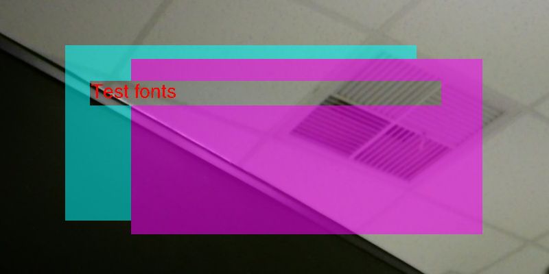
Figure 6‑1: enable alpha blending function -
enable
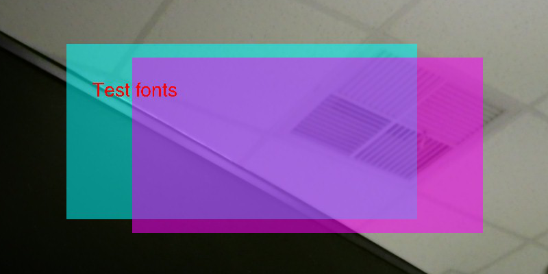
Figure 6‑2: disable alpha blending function