SGS TrustZone Debug SOP
Revision History
| Revision NO. | Description |
Data |
|---|---|---|
| 1.0 | Initial release | 06/25/2025 |
1. Overview
In systems that use TrustZone, hardware-level protection is applied to IPs (RIU bank/register), IMI, and DRAM. This document provides debugging procedures for these hardware-level protections.
The most commonly encountered issue is that a feature works correctly in a system where TrustZone is disabled, but fails once TrustZone is enabled. This document provides a procedure for determining whether TrustZone is the root cause of such issues.
2. Related Hardware
-
TZSP (TrustZone Security Property): TZSP implements hardware-level protection for IPs. This document describes how to investigate whether a problem is caused by illegal access to IP registers.
-
TZIMI (TrustZone Internal Memory Interface): TZIMI implements hardware-level protection for IMI. This document describes how to investigate whether a problem is caused by illegal access to IMI.
-
TZEMI (TrustZone External Memory Interface): TZEMI implements hardware-level protection for DRAM. This document describes how to investigate whether a problem is caused by illegal access to DRAM.
3. Troubleshooting Flow
3.1. Troubleshooting Flowchart
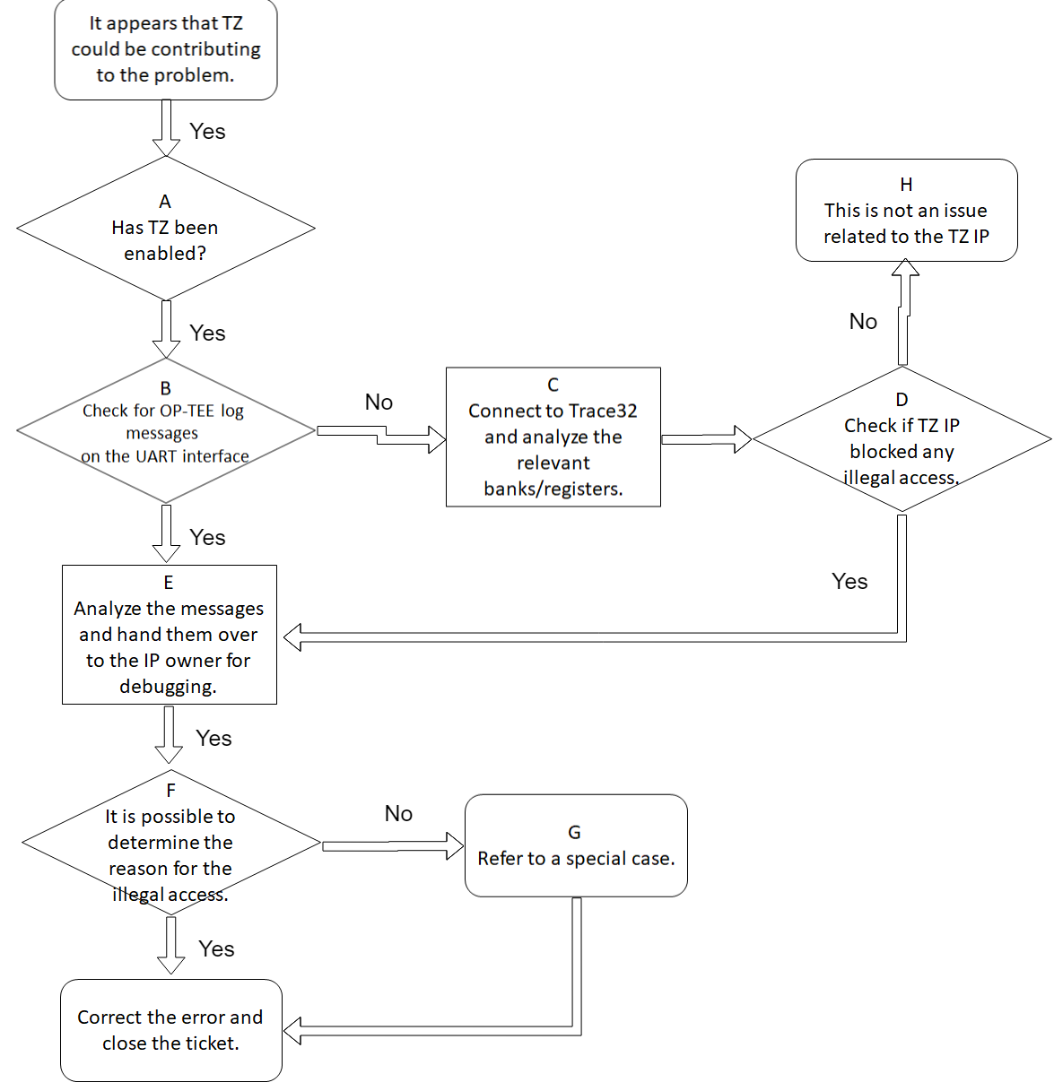
3.2. Step Descriptions
| Flow Node | Node Description |
Exit | Data to Provide for Analysis |
|---|---|---|---|
| A | Confirm TZ enable status | B H | - |
| B | Check whether the UART log contains TZ IP print messages from OP-TEE, refer to relevant section | C E | TZ access violation |
| C | When no OP-TEE messages are present, use T32 to inspect the bank/register | D | - |
| D | Analyze whether the bank/register indicates an illegal access | E H | TZ access violation |
| E | Analyze the illegal access message and escalate to the IP owner for resolution | F | - |
| F | Determine whether the root cause of the illegal access can be identified | G I | - |
| G | Refer to special cases | I | - |
| H | Issue is not related to TZ IP | - | - |
| I | Apply fix and close the issue | - | - |
4. Confirming Whether TrustZone Is Enabled
The TrustZone enable switch depends on whether OTP_TZ has been programmed. The default value of OTP_TZ is 0, meaning disabled. When OTP_TZ is programmed to 1, TrustZone is enabled. This can be confirmed via the OTP_TZ mirror register at bank 0x101F_30[9]. On a system where OTP_TZ=0, neither hardware nor software drivers will enable TrustZone, and the issue is unrelated to TrustZone.
5. TZSP Troubleshooting
5.1 RIU_DBG Bank for Recording Messages
When a RIU host performs an illegal access to a register in a RIU bank, TZSP records the relevant information in the RIU_DBG bank associated with that RIU bank, as shown in the table below:
| RIU bridge | RIU_DBG bank |
|---|---|
| DIG bridge | 0x1001 |
| CMD bridge | 0x1201 |
| ISP0 bridge | 0x1678 |
| PM bridge | 0x0001 |
5.2 RIU Master IDs
When an illegal access occurs, the ID of the RIU host within each RIU bridge is recorded as follows:
| RIU host | RIU bridge and corresponding ID |
|---|---|
| RISV | DIG/CMD/ISP0/PM: 1 |
| CA7 | DIG/CMD/ISP0: 2, PM: 3 |
| CMDQ0 | DIG/CMD/ISP0: 3 |
| CMDQ1 | DIG/CMD/ISP0: 4 |
| VEN1 | DIG/CMD: 5 |
| DBUS | DIG/CMD/ISP0/PM: 7 |
5.3 Information Recorded in the RIU_DBG Bank
- RIU master that performed the illegal access
- RIU_DBG bank 0x41[15:12]
- The mapping between master number and master ID can be found in the table in Section 5.2
- Whether the illegal access is a read or write
- Read: RIU_DBG bank 0x41[9]; Write: RIU_DBG bank 0x41[8]
- Type of illegal access
- Error type 1: RIU_DBG bank 0x41[11]; Error type 2: RIU_DBG bank 0x41[10]
- Error type 1: A Non-Secure (NS) RIU master accesses a Secure (S) RIU bank
- Error type 2: A TZ-related bank is accessed by a non-S-CPU
- The bank that was illegally accessed
- RIU_DBG bank 0x41[7:0] | 0x40[15:8]
- The address that was illegally accessed
- RIU_DBG bank 0x40[7:1]
- Format: 16-bit RIU address
5.4 OP-TEE Print Messages Upon TZSP Illegal Access Detection
Once OP-TEE has finished initialization, any subsequent TZSP illegal access will trigger a print message, as shown in the figure below:

6. TZIMI Troubleshooting
6.1 Bank for Recording Messages
When an IMI client performs an illegal access to IMI, TZIMI records the relevant information in (TZIMI bank 0x11DE).
6.2 IMI Client IDs
The mapping between codes and IMI client IDs can be found using the following two references:
- IMI client table
enum imi_clientinoptee_os/core/drivers/sgs/tz/$(CHIP)/hal_tzimi.h
6.3 Information Recorded in the TZIMI Bank
-
IMI client that performed the illegal access
- Bank 0x11DE_0x44; each bit represents one IMI client, e.g., bit[0] represents client 0
- The mapping between each IMI client number
RIU host RIU bridge and corresponding ID RISV DIG/CMD/ISP0/PM:1 CA7 DIG/CMD/ISP0:2,PM:3 CMDQ0 DIG/CMD/ISP0:3 CMDQ1 DIG/CMD/ISP0:4 VEN1 DIG/CMD:5 DBUS DIG/CMD/ISP0/PM:7 - Whether the illegal access is a read or write - Bank 0x11DE_0x47[0]: 0 = read, 1 = write - The region that was illegally accessed (region 0 or 1) - Bank 0x11DE_0x47[2]: 0 = region 0, 1 = region 1 - Security attribute of the IMI client that performed the illegal access (S or NS) - Bank 0x11DE_0x47[1]: 0 = Secure (S), 1 = Non-Secure (NS) - Address that was illegally accessed (IMI offset) - Bank 0x11DE_0x45~0x46; only the upper 28 bits of the address are recorded; the lower 4 bits are always 0 - Recorded address = (fail access addr - IMI base) & 0xFFFFFFF0 - When an access to an address beyond the IMI size occurs, TZIMI intercepts it (prior to TZIMI, hardware would wrap around). In this case, the recorded fail region is 0.
6.4 OP-TEE Print Messages Upon TZIMI Illegal Access Detection
Once OP-TEE has finished initialization, any subsequent TZIMI illegal access will trigger a print message, as shown in the figure below:

7. TZEMI Troubleshooting
7.1 Bank for Recording Messages
When a MIU client performs an illegal access to DRAM, TZEMI records the relevant information in (TZEMI bank 0x1618).
7.2 MIU Client IDs
The mapping between codes and MIU client IDs can be found using the following two references:
- MIU client table
enum miu_wr_clientorenum miu_rd_clientinoptee_os/core/drivers/sgs/tz/$(CHIP)/hal_tzemi.h
7.3 Information Recorded in the TZEMI Bank
-
MIU client that performed the illegal access
- Write client: bank 0x1618_0x7A[8:0]; Read client: bank 0x1618_0x7B[8:0]; bit[8:4] = group, bit[3:0] = client within the group
-
Whether the illegal access is a read or write
- Write flag: bank 0x1618_0x7A[10]; Read flag: bank 0x1618_0x7B[10]
- The region that was illegally accessed (0 ~ 16)
- Write region: bank 0x1618_0x7A[15:11]; Read region: bank 0x1618_7B[15:11]
- Security attribute of the MIU client that performed the illegal access (S or NS)
- Write security: bank 0x1618_0x7A[9]; Read security: bank 0x1618_0x7B[9]
- Address that was illegally accessed (MIU offset)
- Write address: bank 0x1618_0x7C~0x7D; Read address: bank 0x1618_0x7E~0x7F
- Addresses recorded here are in units of 32 bytes
- Recorded address = (((fail access addr - MIU base) & 0xFFFFFFE0) >> 4)
- When an access to an address beyond region 0 size occurs, TZEMI intercepts it (prior to TZEMI, hardware would wrap around). In this case, the recorded fail region is 0.
7.4 OP-TEE Print Messages Upon TZEMI Illegal Access Detection
Once OP-TEE has finished initialization, any subsequent TZEMI illegal access will trigger a print message, as shown in the figure below:

8. Special Cases of Illegal Access
8.1 Case 1: U-Boot Cache Line Prefetch Issue
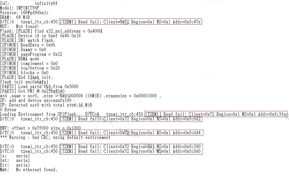
TZEMI intercepted an illegal access. The access failure message indicates: Client 0x72 is the CPU, Region 0x1 is TF-A, the access is an illegal read by NS-CPU, and the addresses are 0xFC47E / 0xFC3FE / 0xFC0D2 / 0xFC0D4 / 0xFC390 / 0xFC0D0 ...
- Root Cause
- After instrumenting the code (code bisection), it was found that the error messages occur immediately upon enabling the D-cache, indicating a cache-related issue.
- This is because once D-cache is enabled, the CPU hardware automatically performs cache line prefetch.
- Prior to this, when executing TF-A, the CPU already had page table entries for the TF-A region.
- Solution
- In U-Boot, set the TF-A region as non-cacheable so that the CPU hardware will not automatically perform cache line prefetch on it.
8.2 Case 2: IMI Access Out-of-Bounds Address Issue
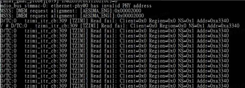
TZIMI intercepted an illegal access. The access failure message indicates: Read fail, Client 0x0 is the CPU, NS=0x1 meaning the access is performed by NS-CPU, Region 0x0, Addr=0x0a3340. Since the IMI size of this chip is 128 KB, any address greater than 128 KB with region 0 is classified as an out-of-bounds access.
- Root Cause
- The issue persisted even after disabling the Linux VM, confirming that the problem originates in RTOS.
- Neither MI nor the image pipeline causes the CPU to access IMI.
- The MMU attribute for IMI in RTOS is
MEM_TYPE_MEMORY | MEM_TYPE_RW | MEM_TYPE_SECURE | MEM_TYPE_INIT_NORMAL, which defines it as a cacheable memory area. - The current MMU page table granularity is 1 MB, which exceeds the actual IMI size.
- Since the CPU hardware automatically performs cache line prefetch when the cache is enabled, any prefetch to an address beyond the actual IMI size causes TZIMI to report an error.
- Solution
- Modify the IMI MMU attribute in RTOS from
MEM_TYPE_MEMORYtoMEM_TYPE_NON_CACHEABLEso that the CPU hardware will not automatically perform cache line prefetch on IMI.
- Modify the IMI MMU attribute in RTOS from