LLM_and_VLM Demo User Guide
1. Feature Introduction
This example demonstrates how to deploy an OpenAI-compatible inference service on the development board. llm_and_vlm Demo covers both LLM text chat and VLM image-text understanding.
1.1. Key Features
- LLM Text Chat: Support text chat requests via OpenAI API
- VLM Image-Text Understanding: Support image-text understanding requests via OpenAI API
- PCIE Cascade: Support model inference by cascading the computing power of two development boards via PCIE
- OpenAI API Compatible: Compatible with the standard OpenAI API interface. Users can invoke the model inference function by sending HTTP requests
/v1/models: Query which models are currently supported/v1/chat/completions: Support text chat and image-text understanding
- Streaming Response: Support both streaming and non-streaming response modes
- KV Cache Management: Automatically manage conversation context
2. Compilation Environment
2.1 Compilation Environment Setup
Set up the arm64 compilation environment in the project root directory:
export PATH=/tools/toolchain/aarch64-unknown-linux-gcc-12.4.0-glibc-2.37-gnu/bin:$PATH
export CROSS_COMPILE=aarch64-unknown-linux-gnu-12.4.0-
export ARCH=arm64
cd project
make linux-comake_mhera.emmc.glibc-12.4.0-arm64-ext4.d3.4096.fccsp16_lpddr4x_defconfig
If using 2GB DDR, the defconfig can use linux-comake_mhera.emmc.glibc-12.4.0-arm64-ext4.d3.2048.fccsp16_lpddr4x_defconfig
2.2 Compilation Commands
# Compile the entire project
cd project
make clean;make image -j16

# Compile LLM_and_VLM demo
cd sdk/verify/sample_code
make llm_and_vlm

# Clean compilation artifacts
make llm_and_vlm_clean

# Compile IPU service (required for PCIE cascade scenario)
cd ../release_feature
make source/ipu/ipu_service
2.3 Compilation Output
sgs_demo_llm_and_vlmexecutable is located insample_code/out/arm64/appdirectoryprog_ipu_ipu_serviceexecutable is located in../release_feature/out/arm64/appdirectory (required for PCIE cascade scenario)
3. Runtime Environment Setup
3.1 Software Requirements
- Cherry Studio (optional): For providing a graphical dialogue interface, see section "4.2.1 Cherry Studio Description"
3.2 Network Environment
The device needs to be able to ping the device sending HTTP requests during runtime. Refer to the following steps to configure a fixed IP for the board:
# Enable network interface
ifconfig eth0 up

# Set MAC address (optional, some boards require this)
ifconfig eth0 hw ether 00:83:16:00:00:01

# Set IP address and subnet mask
ifconfig eth0 192.168.1.100 netmask 255.255.255.0

# Set gateway
route add default gw 192.168.1.254

# Confirm configuration
ifconfig eth0
          Development Board                                         PC End
    ┌─────────────────────────┐                   ┌───────────────────────┐
    │  Fixed IP: 192.168.1.100│◄─────────────────►│  Fixed IP:192.168.1.200│
    └─────────────────────────┘    Direct cable   └───────────────────────┘
3.3 Model Files
Model files are required during runtime and need to be placed in the following directory structure:
sgs_demo_llm_and_vlm        # On-board server executable
models                      # Common root directory for model storage
    LLM                     # LLM model storage directory (non-PCIE cascade scenario)
    VLM                     # VLM model storage directory (non-PCIE cascade scenario)
    PCIE_LLM                # LLM model storage directory for PCIE cascade scenario
LLM, VLM, and PCIE_LLM models can be obtained from the models directory, including the following files:
ipu.json: Model configuration file describing the model's input/output format, parameters, etc.generation_config.json: Model generation configuration parameters- Model weight files and related configuration files
Note:
- For non-PCIE cascade scenarios, choose model files from
LLMorVLMdirectory according to usage requirements - For PCIE cascade scenario, use model files from
PCIE_LLMdirectory - Ensure all model files are complete and versions match
3.4 Non-PCIE Cascade Scenario Environment Setup
3.4.1. Development Board bootargs Configuration
Press and hold the Enter key, then power on the development board to enter the uboot environment. Use printenv to check bootargs parameters, similar to the following output:
bootargs=ubi.mtd=ubia,2048 root=/dev/mtdblock6 rootfstype=squashfs ro init=/linuxrc LX_MEM=0x1000000000,0x100000000 cma=2M mma_heap=mma_heap_name0,miu=0,sz=0x20000000 mma_memblock_remove=1 mtdparts=nand0:1920k@1280k(BOOT),1920k(BOOT_BAK),256k(ENV),256k(ENV1),5m(KERNEL),5m(KERNEL_BACKUP),4m(rootfs),1152k(MISC),109952k(ubia)
Modify mma_heap sz to 0x70000000, then save and restart:
set bootargs ubi.mtd=ubia,2048 root=/dev/mtdblock6 rootfstype=squashfs ro init=/linuxrc LX_MEM=0x1000000000,0x100000000 cma=2M mma_heap=mma_heap_name0,miu=0,sz=0x70000000 mma_memblock_remove=1 mtdparts=nand0:1920k@1280k(BOOT),1920k(BOOT_BAK),256k(ENV),256k(ENV1),5m(KERNEL),5m(KERNEL_BACKUP),4m(rootfs),1152k(MISC),109952k(ubia)

saveenv

reset
3.4.2. Non-PCIE Hardware Connection
The non-PCIE cascade scenario runs on a single board with the following hardware requirements:
- Development Board: One MHERA series development board
- Network Connection: Connect the development board to the LAN via Ethernet or Wi-Fi, ensuring it is on the same network segment as the device sending HTTP requests (e.g., a PC running Cherry Studio) and can ping each other
- Power Supply: Ensure the development board is properly powered
- Debug Serial Port (optional): Connect a serial port for viewing boot logs and debugging information
3.5 PCIE Cascade Scenario Environment Setup
3.5.1. EP End bootargs Configuration
Press and hold the Enter key, then power on the development board to enter the uboot environment. Use the following commands to configure:
setenv bootargs ubi.mtd=ubia,2048 root=/dev/mtdblock6 rootfstype=squashfs ro init=/linuxrc LX_MEM=0x1000000000,0x80000000 cma=2M mma_heap=mma_heap_name0,miu=0,sz=0x60000000 mma_memblock_remove=1 mtdparts=nand0:1920k@1280k(BOOT),1920k(BOOT_BAK),256k(ENV),256k(ENV1),5m(KERNEL),5m(KERNEL_BACKUP),4m(rootfs),1152k(MISC),109952k(ubia) pcie0=ep pci_epf_test.pcie_port=0

saveenv
reset
3.5.2. RC End bootargs Configuration
setenv bootargs ubi.mtd=ubia,2048 root=/dev/mtdblock6 rootfstype=squashfs ro init=/linuxrc LX_MEM=0x1000000000,0x80000000 cma=2M mma_heap=mma_heap_name0,miu=0,sz=0x60000000 mma_memblock_remove=1 mtdparts=nand0:1920k@1280k(BOOT),1920k(BOOT_BAK),256k(ENV),256k(ENV1),5m(KERNEL),5m(KERNEL_BACKUP),4m(rootfs),1152k(MISC),109952k(ubia) pcie0=rc pciehp.pciehp_poll_mode=1

saveenv
reset
Configuration Description:
pcie0=ep: Configure PCIE0 as EP modepcie0=rc: Configure PCIE0 as RC modeLX_MEM=0x1000000000,0x80000000: PCIE cascade scenario requires larger memory configurationmma_heap sz=0x60000000: Reserve sufficient memory space for model inference
3.5.3. PCIE Cascade Hardware Connection
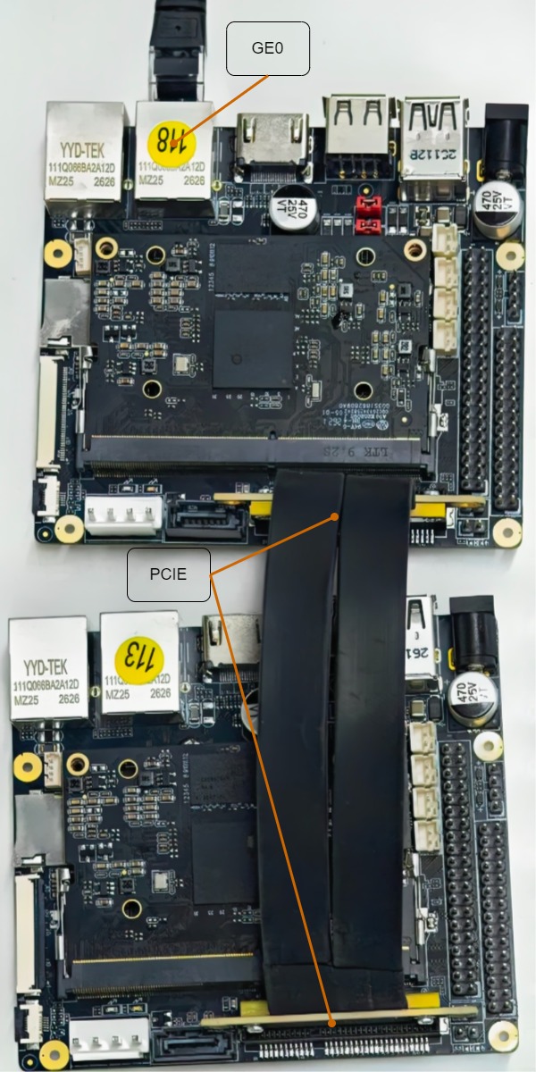
The PCIE cascade scenario requires two development boards connected via the PCIE bus with the following hardware requirements:
Development Board A (RC end)                     Development Board B (EP end)
    ┌─────────────┐                   ┌─────────────┐
    │  PCIE0 port │◄─────────────────►│  PCIE0 port │
    └─────────────┘    PCIE cable     └─────────────┘
         │                                 │
         │ No power connection              │
         │                            Connect power
         ▼                                 ▼
    ┌─────────────┐                   ┌─────────────┐
    │  Serial/Network│                 │  Serial/Network│
    └─────────────┘                   └─────────────┘
- Development Boards: Two MHERA series development boards
- PCIE Cable: Use a PCIE cable to connect the PCIE0 interfaces of both development boards
- RC end (master) PCIE0 interface connects to EP end (slave) PCIE0 interface
- Ensure the cable is intact and the connections are secure
- PCIE0 Speed Limit Resistor: Both development boards need to have the PCIE0 speed limit resistor removed (if present)
- Power Supply:
- EP end development board: Requires normal power supply
- RC end development board: Can be powered from the EP end via the PCIE bus (external power not strictly required)
- It is recommended to connect both boards to power for better stability
- Network Connection: The RC end development board needs to be connected to the LAN, ensuring it can ping the device sending HTTP requests
- Debug Serial Port (optional): Connect serial ports to both boards for viewing boot logs and debugging information
See the diagram below for the specific connections.
3.5.4. PCIE Connection Verification
After startup is complete, execute lspci command on RC end to verify PCIE connection:
If you see similar PCIE device information, the connection is successful. If no devices are returned, please check:
- Whether the board's PCIE socket has dry joints
- Whether the PCIE cable is available
- Whether the bootargs configuration of both boards is correct
4. Running Instructions
4.1 Board-side Running Instructions
4.1.1. Non-PCIE Cascade Description
The non-PCIE cascade scenario runs on a single board. Simply start the board-side program.
4.1.1.1. Basic Usage
4.1.1.2. Command Line Arguments
| Parameter | Description | Default Value |
|---|---|---|
-d <listen_host> |
Network address to listen on | 0.0.0.0 |
-p <listen_port> |
Network port number to listen on | 8000 |
-l <model_path> |
Model file path (directory where ipu.json is located) | ./models/LLM |
-h |
Print help information | - |
4.1.1.3. Usage Examples
LLM Scenario
# Listen on network address 192.168.1.100, port 9090, use default model path
./sgs_demo_llm_and_vlm -d 192.168.1.100 -p 9090

# Specify model path as ./models/LLM
./sgs_demo_llm_and_vlm -d 192.168.1.100 -p 9090 -l ./models/LLM
VLM Scenario
# Listen on network address 192.168.1.100, port 9090, specify VLM model path
./sgs_demo_llm_and_vlm -d 192.168.1.100 -p 9090 -l ./models/VLM
4.1.2. PCIE Cascade Description
The PCIE cascade scenario requires starting the EP end and RC end programs separately.
4.1.2.1. EP End Startup
After the EP end program starts, it will wait for connection requests from the RC end.
4.1.2.2. RC End Startup
4.1.2.3. Command Line Arguments
| Parameter | Description | Default Value |
|---|---|---|
-d <listen_host> |
Network address to listen on | 0.0.0.0 |
-p <listen_port> |
Network port number to listen on | 8000 |
-l <model_path> |
Model file path (directory where ipu.json is located) | ./models/LLM |
-h |
Print help information | - |
Note: In PCIE cascade scenario, the -l parameter should be specified as ./models/PCIE_LLM directory.
4.1.2.4. Usage Examples
# EP end, execute before RC end
./prog_ipu_ipu_service

# RC end, listen on network address 192.168.1.100, port 9090
./sgs_demo_llm_and_vlm -d 192.168.1.100 -p 9090 -l ./models/PCIE_LLM
4.2 PC-side Verification of Large Language Models
4.2.1. Cherry Studio Description
Cherry Studio is an optional graphical interface that can provide a more friendly dialogue experience.
4.2.1.1. Download Portable Version
Visit the Cherry Studio official website to download the portable version:
As shown below:
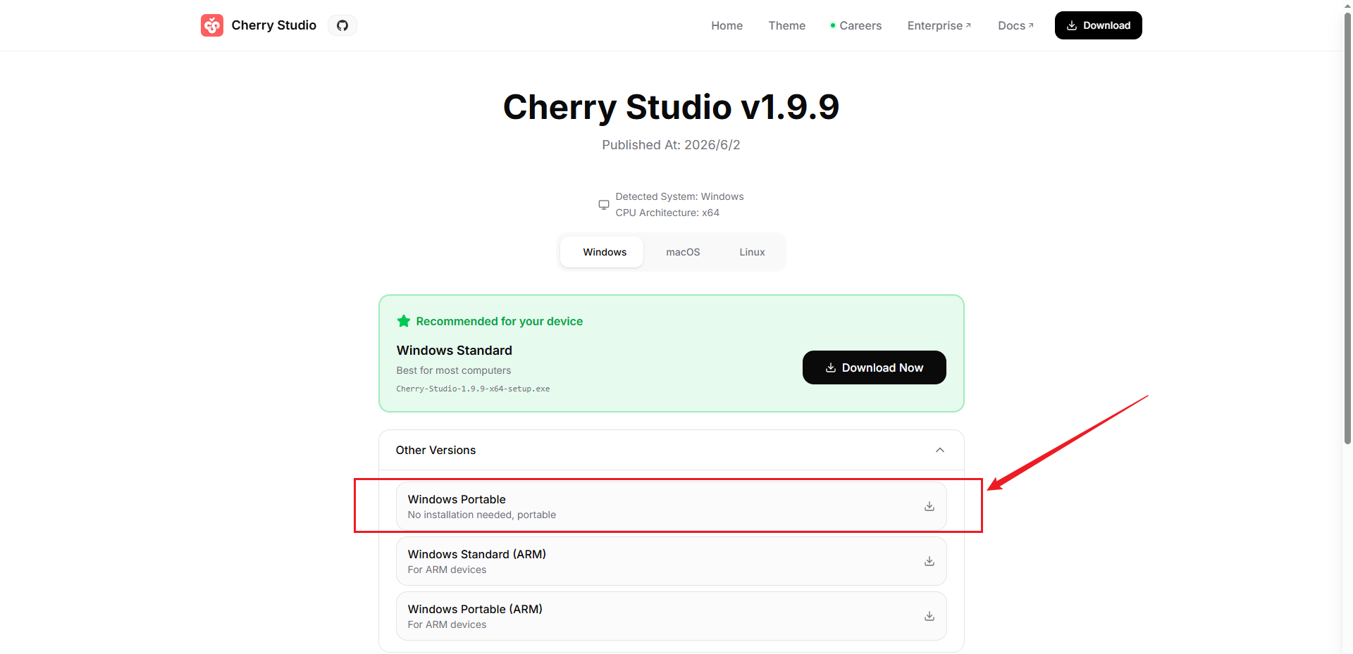
In "Other Versions", download the Windows portable version Cherry-Studio-1.9.9-x64-portable.exe file.
After downloading, simply double-click the .exe file to use it directly without installation.
4.2.1.2. Configure OpenAI API Connection
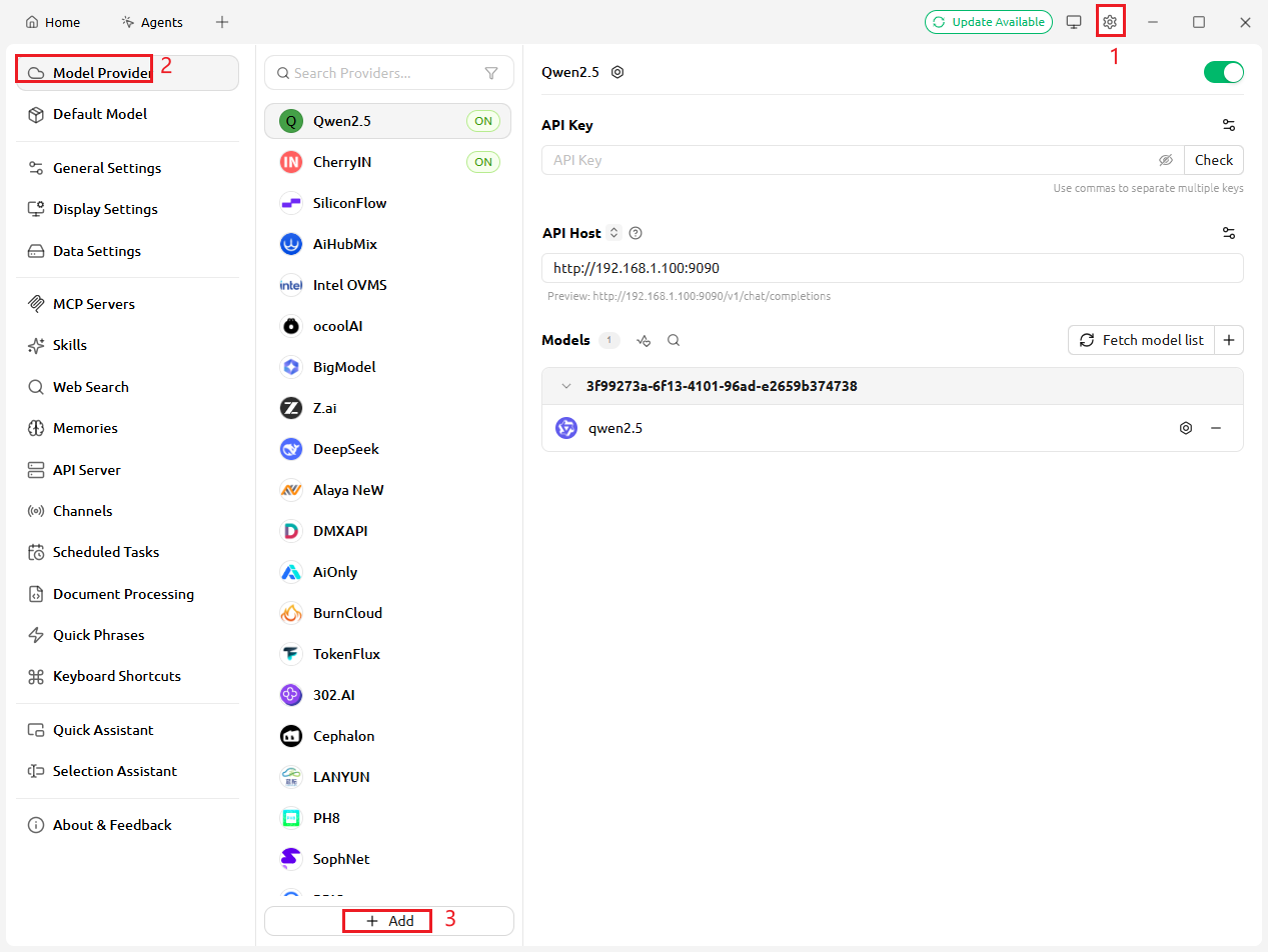
- Click the settings button on the interface to open the settings panel
-
Select the "Model Services" tab, then click "+ Add", as shown below:
-
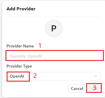
Under "Add Provider", fill in the provider name (e.g., "Assistant"), select "OpenAI" as the provider type, and click "OK" to create an external link model. Refer to the image below:
-
In the OpenAI provider configuration:
- Modify the Base URL to the on-board model server address in the format:
http://<board_ip>:<port>/v1 - For example:
http://192.168.1.100:9090/v1 - API Key can be filled with any non-empty string (such as
sk-test)
- Modify the Base URL to the on-board model server address in the format:
-
After saving the configuration, run the on-board llm demo:
./sgs_demo_llm_and_vlm -d 192.168.1.100 -p 9090 -l ./models/LLM/When the board showsServer listening on http://192.168.1.100:9090log, you can click to fetch the model list and link to the board's model service. Refer to the image below for specific operation:
4.2.1.3. Using Cherry Studio for Dialogue
- Select the configured model in the chat interface
- Enter text questions or upload images for dialogue
- View the returned dialogue results
4.2.2. PowerShell curl Commands Description
In addition to using the Cherry Studio graphical interface, you can also directly call the board-side OpenAI API through PowerShell's curl command (actually Invoke-WebRequest) for testing.
4.2.2.1. Query Model List
4.2.2.2. LLM Text Chat
curl -X POST http://192.168.1.100:9090/v1/chat/completions `
  -H 'Content-Type: application/json' `
  -d '{"model":"default-model","messages":[{"role":"user","content":"hello"}]}'
4.2.2.3. VLM Image-Text Understanding
Method 1: Using PowerShell here-string (recommended)
$imagePath = "C:\path\to\test.jpg"
$imageBytes = [System.IO.File]::ReadAllBytes($imagePath)
$base64Image = [System.Convert]::ToBase64String($imageBytes)

$jsonPayload = @"
{
  "model":"default-model",
  "messages":[{
    "role":"user",
    "content":[
      {"type":"text","text":"describe this image"},
      {"type":"image_url","image_url":{"url":"data:image/jpeg;base64,$base64Image"}}
    ]
  }]
}
"@

curl -X POST http://192.168.1.100:9090/v1/chat/completions `
  -H 'Content-Type: application/json' `
  -d $jsonPayload
Method 2: Build JSON file first
$imagePath = "C:\path\to\test.jpg"
$imageBytes = [System.IO.File]::ReadAllBytes($imagePath)
$base64Image = [System.Convert]::ToBase64String($imageBytes)

$jsonContent = @"
{
  "model":"default-model",
  "messages":[{
    "role":"user",
    "content":[
      {"type":"text","text":"describe this image"},
      {"type":"image_url","image_url":{"url":"data:image/jpeg;base64,$base64Image"}}
    ]
  }]
}
"@

$jsonContent | Out-File -FilePath "C:\temp\vlm_request.json" -Encoding utf8

curl -X POST http://192.168.1.100:9090/v1/chat/completions `
  -H 'Content-Type: application/json' `
  -d @C:\temp\vlm_request.json
5. Viewing Runtime Results
5.1 Normal Startup
The program will display initialization completion information after startup:
5.2 Runtime Logs
- Accept HTTP requests and output responses
- When receiving requests from
/v1/models, return the list of currently supported models -
When receiving requests from
/v1/chat/completions, complete text chat or image-text understanding inference based on the request content and return the responsellm prompt: who are you?
[HTTP] POST /v1/chat/completions handled in 4167.039167 ms
[HTTP] GET /v1/models handled in 0.051834 ms
llm prompt: write a doc to introduce openclaw
[HTTP] POST /v1/chat/completions handled in 22684.127836 ms
VLM Image Processing Logs:
[llm_and_vlm][vision] ALGO_STS_GetInputAttr begin
[llm_and_vlm][vision] ALGO_STS_GetInputAttr ret=0 width=1024 height=1024 format=1
[llm_and_vlm][vision] ALGO_STS_SetParams begin
the set image pad is <image>
[llm_and_vlm][vision] ALGO_STS_SetParams ret=0
[llm_and_vlm][vision] MI_SYS_MMA_Alloc size=1572864
[llm_and_vlm][vision] MI_SYS_MMA_Alloc ret=0 phy=2109881856
[llm_and_vlm][vision] MI_SYS_Mmap begin
[llm_and_vlm][vision] MI_SYS_Mmap ret=0 vir=0x7f8d479e00
[llm_and_vlm][vision] cv::imread path=/tmp/algo_openai_img_7aFnFb
[llm_and_vlm][vision] copy NV12 bytes=1572864 buffer=1572864
[llm_and_vlm][vision] ALGO_STS_Generate vision stream begin
[llm_and_vlm][vision] ALGO_STS_Generate vision stream ret=0
5.3. Program Exit
Type q in the terminal and press Enter to exit. The program will:
- Exit the HTTP server
- Clean up SGS_STS resources
- Wait for the HTTP server to finish
-
Exit the program
In PCIE cascade scenario, the EP end program will automatically detect the RC end disconnection and exit.
5.4. Common Issues
5.4.1. Slow Response
This issue is mostly related to the network connection method between the development board and Cherry Studio. If latency is high, it is recommended to use a direct network cable connection between the development board and the PC where Cherry Studio is located.
5.4.2. Repeated Characters Issue
After multiple rounds of dialogue in a single session, the response shows a large number of repeated characters. The context of LLM/VLM models is limited. It is recommended to switch to a new session after about 5 dialogues to clear the context.
5.4.3. PCIE Connection Issues
If no PCIE devices are returned, please check:
- Whether the board's PCIE socket has dry joints
- Whether the PCIE cable is available
- Whether the bootargs configuration of both boards is correct
5.4.4. VLM Image Processing Failure
If VLM image-text understanding fails, please check:
- Whether the image format is supported (JPEG, PNG)
- Whether the image size exceeds the limit
- Whether the model path correctly points to the VLM model directory