USB USER GUIDE
REVISION HISTORY
| Revision No. | Description |
Date |
|---|---|---|
| 1.0 | 01/06/2026 |
1. OVERVIEW
USB(Universal Serial Bus) is a widely used interface standard, mainly used to connect computers with external devices, achieve data transmission and device power supply.
2. KEYWORD DESCRIPTION
-
Device
External hardware, such as USB drives, keyboards, mobile devices, etc., that connects computers or other devices through a USB interface to achieve data transfer, power supply, or expansion functions.
-
Host
USB Host is the main control terminal that controls the USB bus and manages connected devices (such as computers and mobile phones). It is responsible for power supply, data transmission coordination, and driver loading, enabling external devices (such as USB drives and mice) to work properly.
-
EHCI
The Enhanced Host Controller Interface specification defines a register-level interface to the Universal Serial Bus (USB) 2.0 host controller.
-
XHCI
The eXtensible Host Controller Interface specification defines a register-level interface to the Universal Serial Bus (USB) 3.0 host controller that can interface with USB 1.x, 2.0, and 3.x compliant devices.
-
UTMI
The USB2.0 Transceiver Macrocell Interface protocol, defined from the perspective of USB2.0 signal characteristics, is divided into 8-bit and 16-bit data interface.
-
PIPE
USB 3.0 PHY interface protocol.
-
SUPPHY
SATA/USB/PCIE multi-protocol shared PHY, used for scenarios where Port2 shares PHY with PCIE.
3. FUNCTION DESCRIPTION
-
The USB HOST supports various devices such as keyboards, mice, USB flash drives, USB network cards, USB cameras, USB headsets, etc., and also supports USB hubs to expand the number of USB interfaces.
-
The USB device can be configured as a USB camera, USB audio capture and playback, RNDIS, and other devices.
3.1. MHERA
-
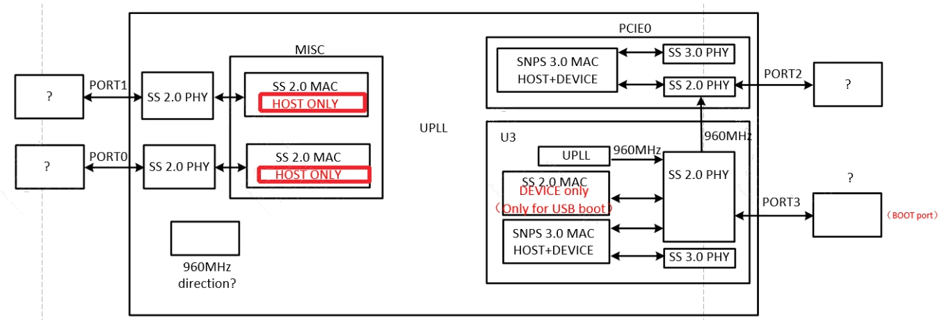
Supports 4 USB ports
-
Two of these ports are USB2.0 host only. The other two ports are USB3.0, which can be used as device or host, denoted as Port2 and Port3. Port3 can be used as a USB2.0 device for usb factory upgrade. The distribution is as follows:
-
USB 3.0 Device EP resources
- 9 independent FIFOs for in EPs, with a total size of 37,408 bytes
- 7 out EPs share an out FIFO of 6,028 bytes
-
USB Port2 and PCIE0 share the same PHY (SUPPHY lane1). The dtsi default is PCIE0 2x + Port2 USB2.0-only (SUPPHY goes to PCIE0, Port2 runs USB2.0 via UTMI only). To run Port2 at USB3.0, the SUPPHY must be given to Port2 (disable PCIE0 or downgrade to 1x). See USB 3.0 DTS Configuration for the DTS configuration of the three usages.
4. Uboot usage introduction
4.1. Using the USB 2.0 Host Driver
4.1.1. USB 2.0 Host menuconfig Configuration
    -> Device Drivers
        -> [*] USB support --->
            -> [*] Enable driver model for USB Gadget
            -> [*] EHCI HCD (USB 2.0) support

    -> [*] Sgs drivers  --->
        -> [*] Sgs USB2.0 Host Controller
        -> [*] Sgs USB Reset Control
4.2. Using the USB 2.0 Device Driver
4.2.1. USB 2.0 Device menuconfig Configuration
    -> Device Drivers
        -> [*] USB support --->
            -> [*] Enable driver model for USB Gadget
            -> [*] USB Gadget Support --->

    -> [*] Sgs drivers  --->
        -> [*] Sgs USB 2.0 Device Controller
        -> [*] Sgs USB Reset Control
        -> [*] USB device uses port1
4.3. Using the USB 3.0 Host Driver
4.3.1. USB 3.0 Host menuconfig Configuration
    -> Device Drivers
        -> [*] USB support --->
            -> [*] Enable driver model for USB Gadget
            -> [*] xHCI HCD (USB 3.0) support

    -> [*] Sgs drivers  --->
        -> [*] DesignWare USB3 Host/Gadget Support on Sgs Platforms
            -> DWC3 Mode Selection (Host only mode)  --->
        -> [*] Sgs USB Reset Control
4.4. Using the USB 3.0 Device Driver
USB3.0 is only used as hosts in Uboot.
If you need to use UFU upgrade, please use Port3 and configure Port3 as USB2.0.
4.5. ufu usage
To enable CMD_SGS_UFU in uboot config, if you need to compile an upgraded uboot with empty chips, you also need to additionally enable CONFIG_SGS_AUTOBOOT_RUN_UFU_ALWAYS
Usage: Enter ufu under uboot to enter ufu upgrade mode and wait for the PC tool to start the upgrade
Note: USB upgrade requires connecting Port 3!
4.6. usbstar usage
The uboot configuration needs to enable CONFIG_CMD_SGS_USBSTAR
Usage: Execute ./image/makefiletools/script/make_usb_upgrade_sgs.sh in project directory, put the generated bin into a Fat32 USB flash drive and connect it to the USB HOST port, Enter usbstar under uboot to start upgrading
5. Introduction to kernel usage
5.1. LINUX CONFIGURATION USING USB DEVICE
5.1.1. Kernel Config Configuration
The device configuration method mainly involves enabling UDC configuration (USB2.0: udc-msx250x.ko, USB3.0: dwc3.ko and sgs-dwc3-of-simple.ko) and some gadget configurations. (depending on which function is needed)
Enable the Gadget core layer and UDC configuration. (Generate usb-common.ko, udc-core.ko, udc-msb250x.ko)
-
USB2.0
Generate: usb-common.ko、udc-core.ko、udc-msb250x.ko sgs-usb2-phy.ko
[*] USB support  --->
    [M] USB Gadget Support  --->
        USB Peripheral Controller  --->
            [M]Sgs USB 2.0 Device Controller

[*] SGS SoC platform drivers --->
    -> <M> SGS USB2 PHY Driver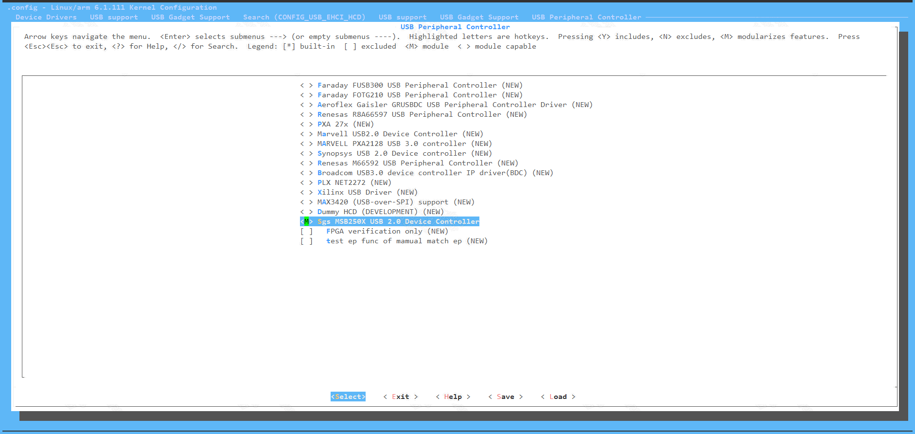
-
USB3.0
Generate: usb-common.ko usbcore.ko udc-core.ko roles.ko sgs-usb3-phy.ko dwc3.ko sgs-dwc3-of-simple.ko
-> [*] USB support --->
    -> <M> Support for Host-side USB
    -> <M> DesignWare USB3 DRD Core Support
        -> DWC3 Mode Selection (Dual Role mode)
    -> <M> USB Gadget Support
    -> <M> USB Role Switch Support

-> [*] SGS SoC platform drivers --->
    -> <M> Simple Glue Layer Of SGS For DWC3
    -> <M> SGS USB3 PHY Driver
    -> [*] SGS USB3 PIPE PHY support
    -> [*] SGS USB3 SUPPHY support
Use the configfs script to enable gadget configuration. The red arrow points to the specific device function to be configured. (generate libcomposite.ko, and the ko of the specific function (usb_f_xxx.ko))
[*]USB support  --->
[M]USB Gadget Support  --->
[M]USB functions configurable through configfs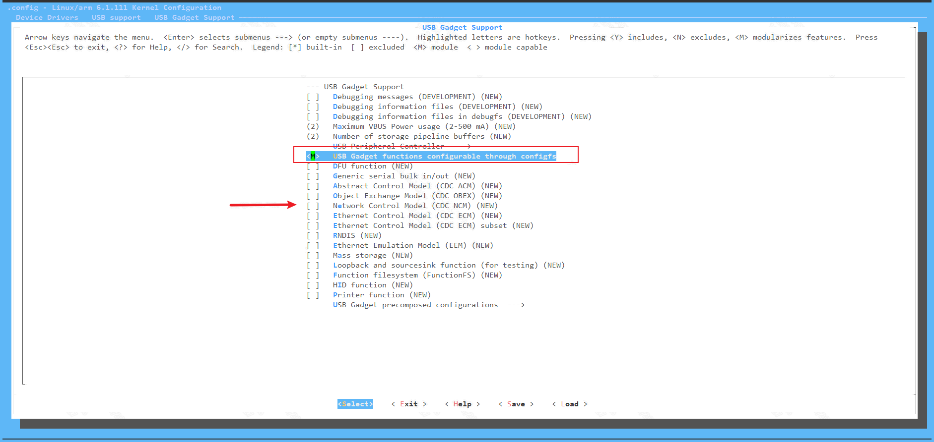
Alternatively, it can configure the gadget by loading the corresponding g_xxx.ko in leagacy way:
[*]USB support  --->
[M]USB Gadget Support  --->
USB Gadget precomposed configurations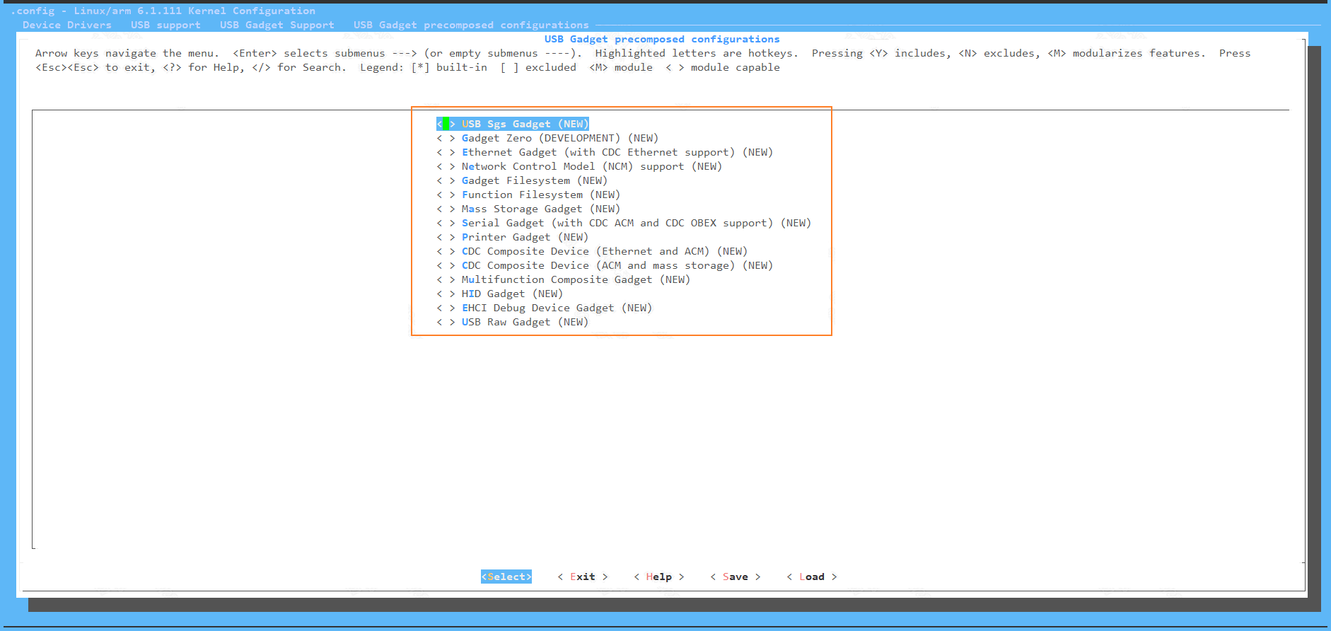
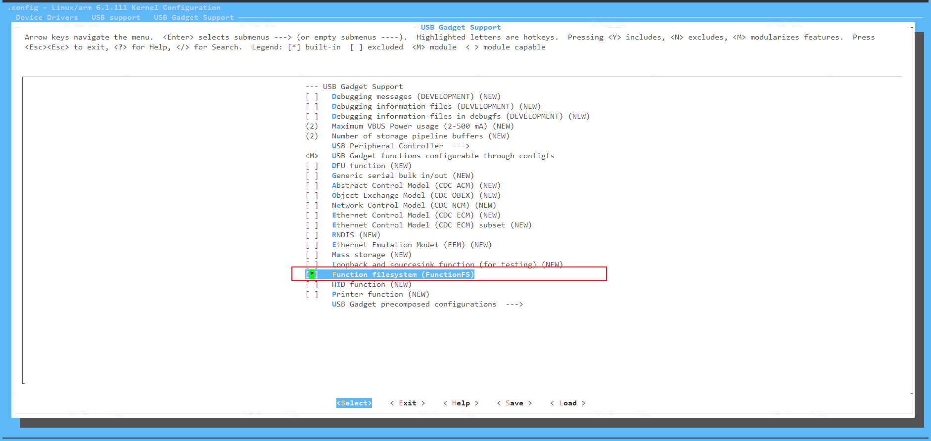
For example, adb needs to open the following configuration. (generate usb_f_fs.ko):
5.1.2. DTS Configuration
5.1.2.1. USB 2.0 Device
The USB 2.0 node in mhera.dtsi is as follows. msb250x-udc-p3 corresponds to Port 3. Currently, Port3 is used as USB 3.0 by default in the kernel, and the status of the USB 2.0 device UDC node is disabled by default.
msb250x-udc-p3 {
    compatible = "sgs,msb250x-udc";
    reg = <0 0x1f286e00 0x200>, <0 0x1f28e000 0x200>, <0 0x1f28e400 0x400>, <0 0x1f203c00 0x200>;
    reg-names = "utmi", "usb0", "otg", "chiptop";
    interrupts = <GIC_SPI INT_IRQ_OTG_P3 IRQ_TYPE_LEVEL_HIGH>;
    interrupt-names = "msb250x_udc_p3";
    maximum-speed = "high-speed";
    ep_name = "ep0", "ep1" , "ep2", "ep3", "ep4", "ep5", "ep6";
    ep_maxpkt_limit = <64>, <1024>, <1024>, <64>, <512>, <512>, <64>;
    ep_fifo_size =  <64>, <8192>, <1024>, <64>, <512>, <512>, <64>;
    dma_channel_num = <4>;
    force_device = <0x1f203c00>, <0x55>, <0x0>, <0x1>;
    clocks = <&CLK_upll_960m>;
    status = "disabled";
};
| Parameter | Description | Remarks |
|---|---|---|
| reg | register base addr | Hardware fixed address, cannot be modified |
| reg-names | register names | The driver retrieves the reg based on its name and cannot be modified |
| interrupts | interrupt num | determined by hardware, cannot be modified |
| interrupt-names | interrupt names | Driver retrieves interrupts based on name, cannot be modified |
| maximum-speed | max speed | support high-speed and full-speed |
| ep_name | endpoint name | Driver retrieves the number of EP based on their names, cannot be modified |
| ep_maxpkt_limit | endpoint max packet limit | Hardware fixed value |
| ep_fifo_size | endpoint fifo size | Hardware fixed value |
| dma_channel_num | dma channel num | Hardware fixed value |
| clocks | clocks configuration | Hardware fixed value |
5.1.2.2. USB 3.0 DTS Configuration (Device / Host Common)
The USB 3.0 Device and Host DTS configurations are structurally identical. Only the dr_mode field in the dwc3 child node needs to be modified: "peripheral" for Device mode, "host" for Host mode.
Note:
- USB Port2 and PCIE0 share the same PHY (SUPPHY lane1). There are three usages depending on which side owns the SUPPHY:
- PCIE0 2x + Port2 USB2.0-only (dtsi default):
u3phy_p2_utmi,usb3drd_p2are okay,u3phy_p2_pipe(SUPPHY) stays disabled so PCIE0 owns it, dwc3maximum-speed="high-speed"withphysreferencing onlyu3phy_p2_utmiandphy-namesonly"usb2-phy", plussgs,combo-phy-reset;added tousb3drd_p2(USB side does the combo reset on behalf of SUPPHY, so Port2 USB2.0 does not depend on PCIE0/SUPPHY probe). - Port2 USB3.0: disable PCIE0 (or downgrade to 1x), set
u3phy_p2_utmi,u3phy_p2_pipe,usb3drd_p2to okay, dwc3maximum-speed="super-speed",physreferencing utmi+pipe,phy-namesincluding"usb3-phy"(i.e. the Port2 config block below). - PCIE0 2x + Port2 unused: Port2 related nodes stay disabled.
- PCIE0 2x + Port2 USB2.0-only (dtsi default):
- UTMI PHY and PIPE/SUPPHY PHY are independent top-level nodes, no longer nested as child nodes under a parent container.
Port 3 (using PIPE PHY, independent USB3 PHY) configuration is as follows:
u3phy_p3_utmi: utmi@1f286e00 {
    compatible = "sgs,generic-utmi";
    reg = <0x0 0x1f286e00 0x200>;
    clocks = <&CLK_upll_480m>;
    //sgs,dp-dm-swap;
    #phy-cells = <0>;
    status = "okay";
};

u3phy_p3_pipe: pipe@1f2a5200 {
    compatible = "sgs,generic-pipe";
    reg = <0x0 0x1f2a5200 0x800>;
    clocks = <&CLK_ssusb_phy_108>, <&CLK_ssusb_phy_432>;
    //sgs,synthesiszer-clk = <0x001ba5e3>;
    sgs,spread-spectrum-clock-enabled = <0x001bb7a0>, <0x03ed>, <0x0004>;
    sgs,tx-swing-and-de-emphasis = <0x3c>, <0x27>, <0x07>;
    //sgs,force-r-term-disabled;
    sgs,en-dynamic-symblock;
    sgs,rx-lfps-burst-gap = <0x3e8>;
    sgs,rx-lfps-deglitch = <1>;   /* 0=67mV, 1=110mV, 2=150mV, 3=210mV */
    #phy-cells = <0>;
    port_id = <3>;
    status = "okay";
};

drd_gp_syscon_p3: drd-gp-syscon-p3@1f286600 {
    compatible = "sgs,generic-usb30-drd-gp-syscon", "syscon";
    reg = <0x0 0x1f286600 0x200>;
    reg-io-width = <2>;
};

drd_mac_syscon_p3: drd-mac-syscon-p3@1f286c00 {
    compatible = "sgs,generic-usb30-drd-mac-syscon", "syscon";
    reg = <0x0 0x1f286c00 0x200>;
    reg-io-width = <2>;
};

usb3drd_p3: usb3-p3 {
    compatible = "sgs,generic-dwc3";
    clocks = <&CLK_sof_usb30_drd>, <&CLK_ssusb_axi>;
    sgs,x2a-addr-off = <0x000000>, <0x000002>, <0x000004>, <0x000008>;
    sgs,usb3drd-gp-syscon = <&drd_gp_syscon_p3>;
    sgs,usb3drd-mac-syscon = <&drd_mac_syscon_p3>;
    usb-phy = <&u3phy_p3_utmi>;
    #address-cells = <2>;
    #size-cells = <1>;
    ranges;
    status = "okay";

    dwc3_p3: dwc3 {
        dr_mode = "peripheral";   /* "peripheral" for Device, "host" for Host */
        compatible = "snps,dwc3";
        reg = <0x0 0x1f348000 0x1400>;
        maximum-speed = "super-speed";
        interrupts = <GIC_SPI INT_IRQ_USB30_DRD_GP2TOP IRQ_TYPE_LEVEL_HIGH>;
        interrupt-names = "dwc_usb3";
        phy_type = "utmi_wide";
        phys = <&u3phy_p3_utmi>, <&u3phy_p3_pipe>;
        phy-names = "usb2-phy", "usb3-phy";
        snps,incr-burst-type-adjustment = <1>, <4>, <8>, <16>, <32>, <64>, <128>;
        snps,dis_u3_susphy_quirk;
        snps,dis_u2_susphy_quirk;
        snps,dis-u1-entry-quirk;
        snps,dis-u2-entry-quirk;
        snps,usb3_lpm_capable;   /* for XHCI_LPM_SUPPORT*/
        snps,parkmode-disable-ss-quirk;
        linux,sysdev_is_parent;
        port_id = <3>;

        snps,ep-maxpktnum = <1>, <6>, <6>, <6>, <1>, <1>, <1>, <1>, <6>;
        status = "okay";
    };
};
Port 2 (using SUPPHY, shared with PCIE0 PHY) configuration for USB3.0 is as follows. In this scenario the SUPPHY must be given to Port2 (disable PCIE0 or downgrade to 1x), and the UTMI/SUPPHY/usb3drd nodes set to okay (the config block below shows this enabled state):
The dtsi default is PCIE0 2x + Port2 USB2.0-only (
u3phy_p2_pipestays disabled, dwc3high-speedreferencing only usb2-phy,usb3drd_p2carriessgs,combo-phy-reset). For the three usages and full switching steps, see the notes in USB 3.0 DTS Configuration; not repeated here.
u3phy_p2_utmi: utmi@1f290000 {
    compatible = "sgs,generic-utmi";
    reg = <0x0 0x1f290000 0x200>;
    clocks = <&CLK_upll_480m>;
    //sgs,dp-dm-swap;
    #phy-cells = <0>;
    status = "okay";
};

u3phy_p2_pipe: pipe@1f2b2600 {
    compatible = "sgs,supphy";
    reg = <0x0 0x1f2b2600 0x600>;
    clocks = <&CLK_ssusb_phy_108>, <&CLK_ssusb_phy_432>;
    sgs,spread-spectrum-clock-enabled = <0x00162c37 0x04E9 0x0003 0x17>; /* synth_set, span_set, step_set, pll_lock_offset */
    #phy-cells = <0>;
    port_id = <2>;
    status = "okay";
};

drd_gp_syscon_p2: drd-gp-syscon-p2@1f287000 {
    compatible = "sgs,generic-usb30-drd-gp-syscon", "syscon";
    reg = <0x0 0x1f287000 0x200>;
    reg-io-width = <2>;
};

drd_mac_syscon_p2: drd-mac-syscon-p2@1f287200 {
    compatible = "sgs,generic-usb30-drd-mac-syscon", "syscon";
    reg = <0x0 0x1f287200 0x200>;
    reg-io-width = <2>;
};

usb3drd_p2: usb3-p2 {
    compatible = "sgs,generic-dwc3";
    clocks = <&CLK_sof_usb30_drd>, <&CLK_ssusb_axi>;
    sgs,x2a-addr-off = <0x000000>, <0x000002>, <0x000004>, <0x000008>;
    sgs,usb3drd-gp-syscon = <&drd_gp_syscon_p2>;
    sgs,usb3drd-mac-syscon = <&drd_mac_syscon_p2>;
    usb-phy = <&u3phy_p2_utmi>;
    #address-cells = <2>;
    #size-cells = <1>;
    ranges;
    status = "okay";

    dwc3_p2: dwc3 {
        dr_mode = "peripheral";   /* "peripheral" for Device, "host" for Host */
        compatible = "snps,dwc3";
        reg = <0x0 0x1f352000 0x1400>;
        maximum-speed = "super-speed";
        interrupts = <GIC_SPI INT_IRQ_USB30_DRD_GP2TOP_P1 IRQ_TYPE_LEVEL_HIGH>;
        interrupt-names = "dwc_usb3";
        phy_type = "utmi_wide";
        phys = <&u3phy_p2_utmi>, <&u3phy_p2_pipe>;
        phy-names = "usb2-phy", "usb3-phy";
        snps,incr-burst-type-adjustment = <1>, <4>, <8>, <16>, <32>, <64>, <128>;
        snps,dis_u3_susphy_quirk;
        snps,dis_u2_susphy_quirk;
        snps,usb3_lpm_capable;
        snps,parkmode-disable-ss-quirk;
        linux,sysdev_is_parent;
        port_id = <2>;

        snps,ep-maxpktnum = <1>, <6>, <6>, <6>, <1>, <1>, <1>, <1>, <6>;
        status = "okay";
    };
};
Attribute of usb3drd Node
| Attribute | Description | Note |
|---|---|---|
| compatible | Used for matching drivers for registration | Do not modify |
| clocks | Used to enable all used clocks | Do not modify |
| sgs,x2a-addr-off | Used to set dwc3 register to map to Sgs bank | Do not modify |
| sgs,usb3drd-gp-syscon | Specifies the GP bank and range occupied by usb30, which is convenient for using regmap to access registers | Do not modify |
| sgs,usb3drd-mac-syscon | Specifies the MAC bank and range occupied by usb30, which is convenient for using regmap to access registers | Do not modify |
| usb-phy | Specifies the USB PHY node for disconnect notification | Do not modify |
| #address-cells | Used to specify the word length (32bit) occupied by the address information of the reg attribute of the child node | Do not modify |
| #size-cells | Used to specify the word length (32bit) occupied by the address range information of the reg attribute of the child node | Do not modify |
| ranges | Used to indicate that the child node inherits #address-cells and #size-cells attributes | Do not modify |
| status | Choose whether to enable the USB3 driver | Modify as needed |
Attribute of dwc3 Node
| Attribute | Description | Note |
|---|---|---|
| compatible | Used for matching drivers for registration | Do not modify |
| reg | Used to specify the bank register address range occupied by dwc3 | Do not modify |
| dr_mode | Used to specify the dwc3 mode, host or peripheral | Modify as needed |
| maximum-speed | Used to specify the maximum rate supported by dwc3 | Modify as needed |
| interrupts | Used to specify the interrupt and triggering method of dwc3 | Do not modify |
| interrupts-names | Used for the name of the interrupts attribute, corresponding to the interrupts attribute | Do not modify |
| phy_type | Used to specify the phy type | Do not modify |
| phys | Used to specify the phy list supported by usb30 | Modify as needed |
| phy-names | Used to specify the name of the phy list supported by the phys attribute, corresponding to the phy list one-to-one | Modify as needed |
| snps,incr-burst-type-adjustment | Used to specify the number of burst bytes supported by dwc3 MAC when accessing DDR | Do not modify |
| snps,dis_u3_susphy_quirk | Synopsis native quirk attribute | Do not modify |
| snps,dis_u2_susphy_quirk | Synopsis native quirk attribute | Do not modify |
| snps,dis-u1-entry-quirk | Set if link entering into U1 needs to be disabled | Do not modify |
| snps,dis-u2-entry-quirk | Set if link entering into U2 needs to be disabled | Do not modify |
| snps,usb3_lpm_capable | Used to enable USB3 link power management | Do not modify |
| linux,sysdev_is_parent | Used to specify the sysdev driven by the host hcd, not used by device | Do not modify |
| status | Choose whether to enable the driver | Modify as needed |
5.1.3. Ko Loading
5.1.3.1. USB 2.0
USB2.0 device is not supported in the kernel.
5.1.3.2. USB 3.0
Load ko in the following order:
    usb-common.ko
    usbcore.ko
    udc-core.ko
    roles.ko
    sgs-usb3-phy.ko
    dwc3.ko
    sgs-dwc3-of-simple.ko
    libcomposite.ko
    #device function ko
    for example, adb need to load usb_f_fs.ko
    #if using leagacy configuration, need to load g_xxx.ko
5.2. LINUX CONFIGURATION USING USB HOST
5.2.1. Kernel Config Configuration
Kernel config open the following configuration:
-
USB2.0
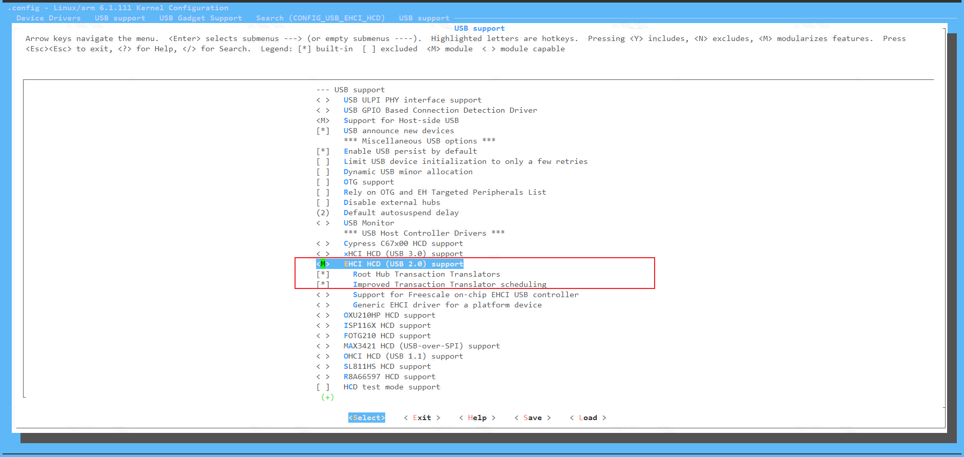
COFNIG_USB_EHCI_HCD: (generate ehci-hcd.ko)
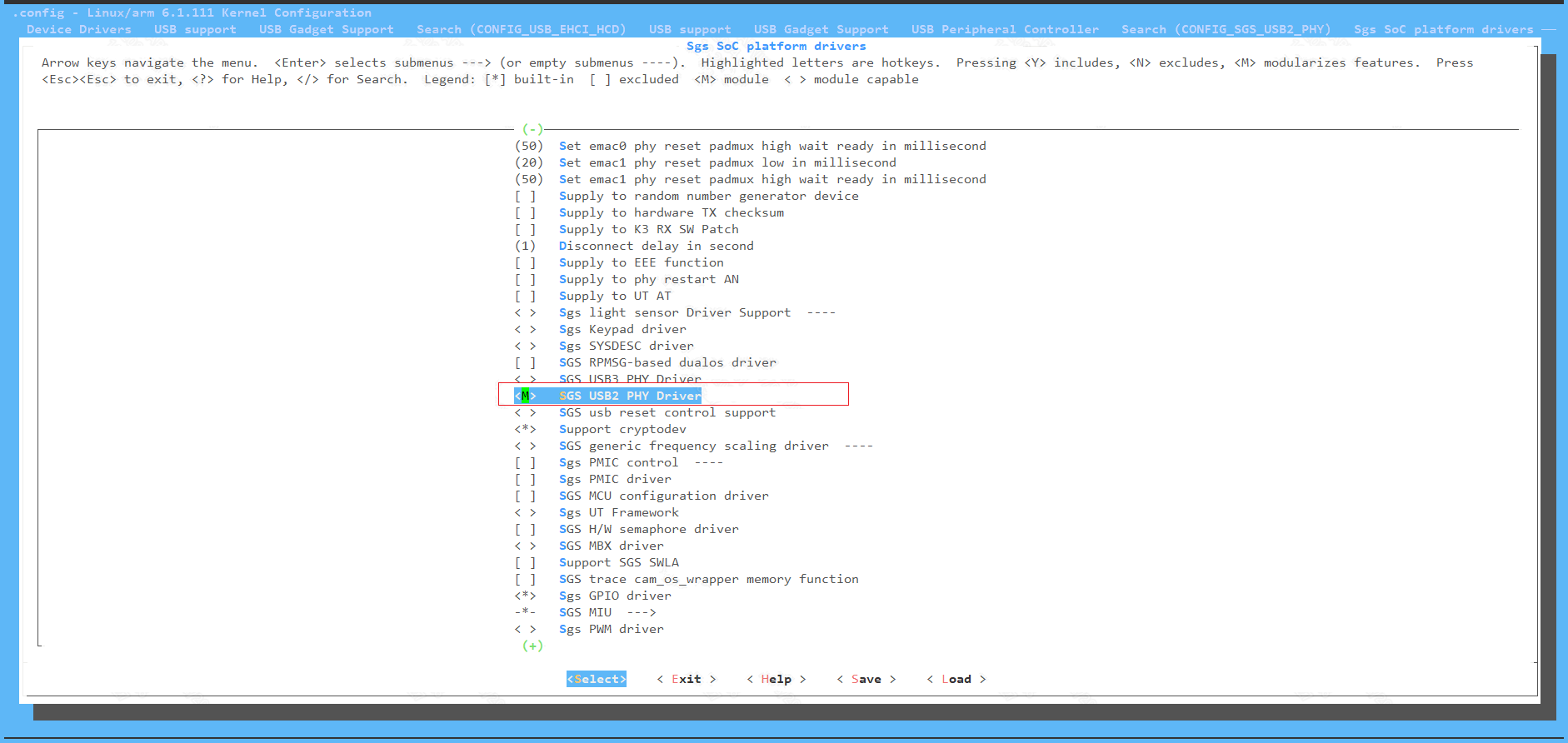
CONFIG_SGS_USB2_PHY: (generate sgs-usb2-phy.ko)
-
USB3.0
->[*] USB support --->
    -> <M> Support for Host-side USB
    -> <M> xHCI HCD (USB 3.0) support
    -> <M> Generic xHCI driver for a platform device
    -> <M> DesignWare USB3 DRD Core Support
        -> DWC3 Mode Selection (Dual Role mode)
    -> <M> USB Gadget Support
    -> <M> USB Role Switch Support

-> [*] SGS SoC platform drivers --->
    -> <M> Simple Glue Layer Of SGS For DWC3
    -> <M> SGS USB3 PHY Driver
    -> [*] SGS USB3 PIPE PHY support
    -> [*] SGS USB3 SUPPHY support
Select the above options and compile: usb-common.ko usbcore.ko udc-core.ko roles.ko sgs-usb3-phy.ko dwc3.ko sgs-dwc3-of-simple.ko xhci-hcd.ko xhci-plat-hcd.ko
5.2.2. DTS Configuration
5.2.2.1. USB 2.0
The corresponding node in mhera.dtsi is as follows. By default, both USB 2.0 host ports are enabled.
sgs-ehci-1 {
    compatible = "sgs,ehci";
    reg-names = "ehc_base";
    reg = <0x0 0x1f284800 0x200>;
    clocks = <&CLK_upll_480m>;
    interrupts = <GIC_SPI INT_IRQ_UHC_P0 IRQ_TYPE_LEVEL_HIGH>;
    phys = <&sgs_u2phy1>;
    phy-names = "usb";
    support_high_2g_access_patch;
    port_id = <0>;
    status = "okay";
};

sgs-ehci-2 {
    compatible = "sgs,ehci";
    reg-names = "ehc_base";
    reg = <0x0 0x1f286400 0x200>;
    clocks = <&CLK_upll_480m>;
    interrupts = <GIC_SPI INT_IRQ_UHC_P1 IRQ_TYPE_LEVEL_HIGH>;
    phys = <&sgs_u2phy2>;
    phy-names = "usb";
    support_high_2g_access_patch;
    port_id = <1>;
    status = "okay";
};
| Parameter | Description | Notes |
|---|---|---|
| reg | register base address | hardware fixed address |
| interrupts | interrupt num | Fixed Interrupt |
| phys | phy nodes | The referenced phy node |
| phy-names | phy name | Drive to obtain phy nodes based on this |
| clocks | clock configuration | Clock source |
5.2.2.2. USB 3.0
The USB 3.0 Host DTS configuration is identical to the USB 3.0 DTS Configuration. Only the dr_mode field in the dwc3 child node needs to be set to "host".
5.2.3. Ko Loading
5.2.3.1. USB2.0
Load ko in the following order:
5.2.3.2. USB3.0
    usb-common.ko
    usbcore.ko
    udc-core.ko
    roles.ko
    sgs-usb3-phy.ko
    dwc3.ko
    sgs-dwc3-of-simple.ko
    xhci-hcd.ko
    xhci-plat-hcd.ko
5.3. UVC DEVICE CONFIGURATION
First, please refer to Linux configuration using USB device
5.3.1. Kernel Config Configuration
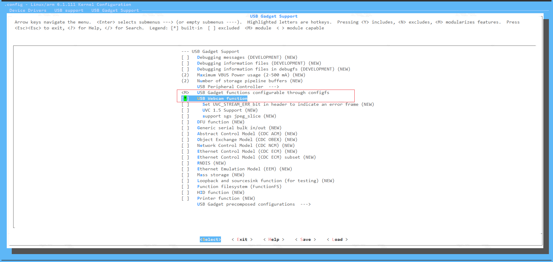
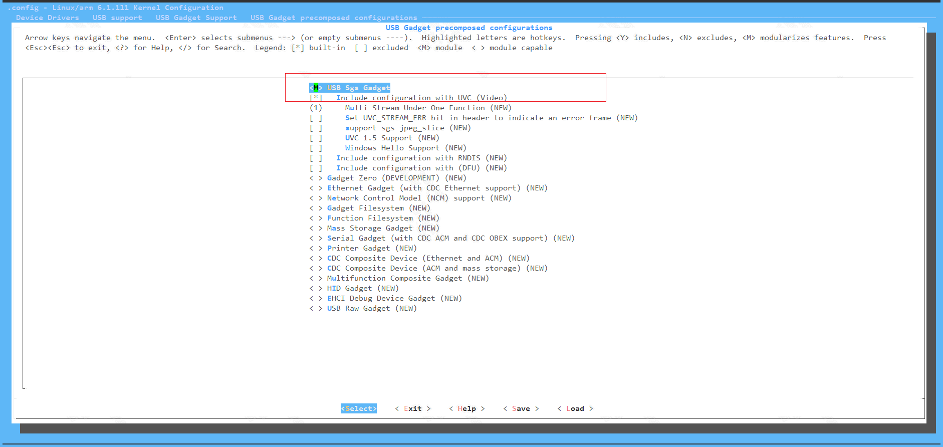
Enable UVC device function configuration (generate ko: libcomposite.ko, usb_f_uvc.ko, g_sgs_gadget.ko)
    Device Drivers  --->
        [*]USB support  --->
            [M]USB Gadget Support  --->
                [M]USB functions configurable through configfs
                USB Gadget precomposed configurations  --->
                    [M]USB Sgs Gadget
                    [*]Include configuration with UVC (Video)
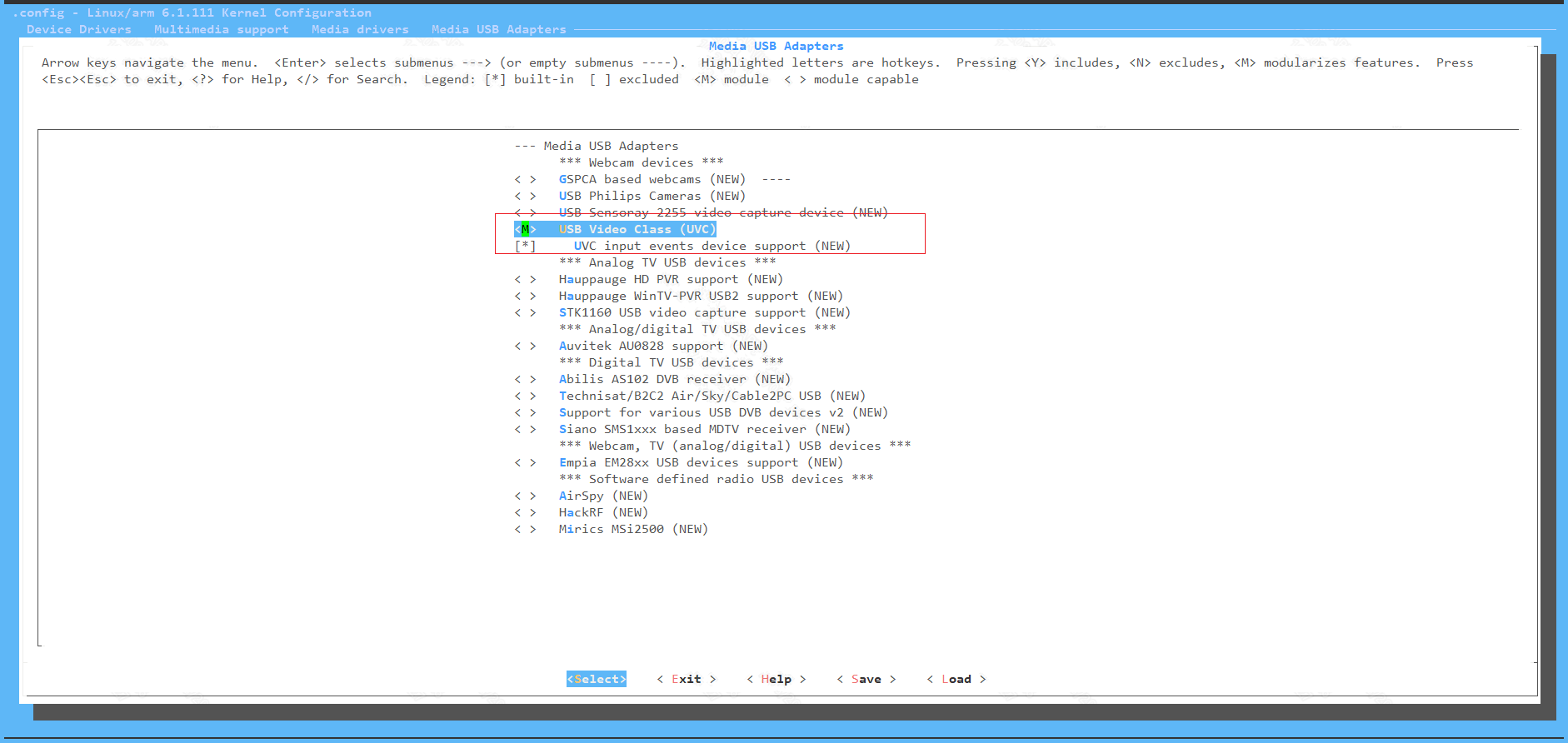
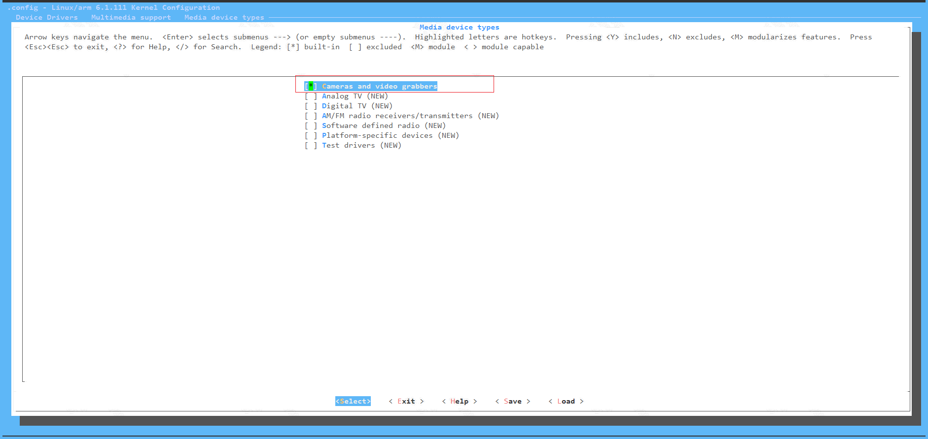
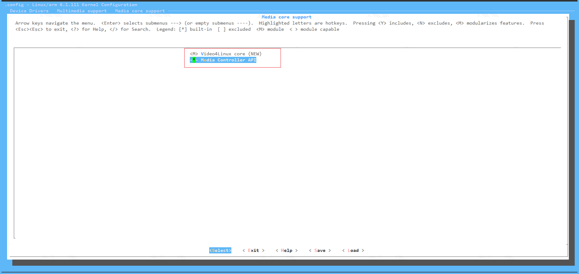
Enable Multimedia configuration (generate ko: mc.ko, videodev.ko, videobuf2-common.ko, videobuf2-v4l2.ko, videobuf2-memops.ko, videobuf2-vmalloc.ko, videobuf2-dma-sg.ko, uvcvideo.ko)
    Device Drivers  --->
        [*]Multimedia support  --->
            Media drivers  --->
                [*]Media USB Adapters  --->
                    [M]USB Vide Class (UVC)
            Media device types  --->
                [*]Cameras and video grabbers
            Media core support  --->
                [*]Media Controller API
5.3.2. Ko Loading
Load ko in the following order:
    usb-common.ko
    usbcore.ko              # for USB3.0 dual role
    udc-core.ko
    udc-msb250x.ko          # for USB2.0 UDC only,--mhera does not support
    roles.ko                # for USB3.0 only
    sgs-usb3-phy.ko         # for USB3.0 only
    dwc3.ko                 # for USB3.0 only
    sgs-dwc3-of-simple.ko   # for USB3.0 only
    libcomposite.ko

    mc.ko
    videodev.ko
    videobuf2-common.ko
    videobuf2-v4l2.ko
    videobuf2-memops.ko
    videobuf2-vmalloc.ko
    videobuf2-dma-sg.ko
    uvcvideo.ko

    usb_f_uvc.ko
    g_sgs_gadget.ko
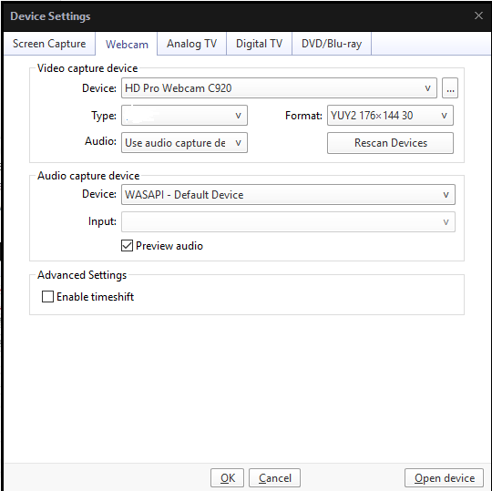
After ko is loaded successfully, the /dev/video0 node will be generated. Connect the USB device port of the board to the PC with a USB cable. Run the UVC demo and use a player such as PotPlayer to open the camera device, the UVC Camera device will appear.
5.4. UVC HOST CONFIGURATION
First, please refer to Linux configuration using USB Host
5.4.1. Kernel Config Configuration
Enable Multimedia configuration (generate ko: mc.ko, videodev.ko, videobuf2-common.ko, videobuf2-v4l2.ko, videobuf2-memops.ko, videobuf2-vmalloc.ko, videobuf2-dma-sg.ko, uvcvideo.ko)
    Device Drivers  --->
        [*]Multimedia support  --->
            Media drivers  --->
                [*]Media USB Adapters  --->
                    [M]USB Vide Class (UVC)
            Media device types  --->
                [*]Cameras and video grabbers
            Media core support  --->
                [*]Media Controller API
5.4.2. Ko Loading
    usb-common.ko
    usbcore.ko
    udc-core.ko             # for USB3.0 dual role
    sgs-usb2-phy.ko         # for USB2.0 only
    ehci-hcd.ko             # for USB2.0 only
    roles.ko                # for USB3.0 only
    sgs-usb3-phy.ko         # for USB3.0 only
    dwc3.ko                 # for USB3.0 only
    sgs-dwc3-of-simple.ko   # for USB3.0 only
    xhci-hcd.ko             # for USB3.0 only
    xhci-plat-hcd.ko        # for USB3.0 only

    #multimedia ko
    mc.ko
    videodev.ko
    videobuf2-common.ko
    videobuf2-v4l2.ko
    videobuf2-memops.ko
    videobuf2-vmalloc.ko
    videobuf2-dma-sg.ko
    uvcvideo.ko
After koes are loaded successfully, the USB host port of the board is connected to the uvc device with a USB cable, and the /dev/videoX node can be seen.
6. USB 2.0 Analog Parameter Adjustment
The following situations require consideration to adjust the driving capability:
-
The eye diagram template test does not pass, or it is not beautiful enough. Modify the driving capability to expect better test results.
-
When encountering some USB2 connections that do not connect, communication interruptions, or other probabilistic USB2-related problems, you want to try and test by modifying the driving capability. In this case, you should essentially return to the first point. However, some systems without eye diagram testing capabilities can only perform black box testing.
The following will take P0 Host as an example.
6.1. Tx swing trim (This parameter has been trimmed by OTP, please confirm with HWRD before modifying)
Located at UTMI bank offset 0x44[9:4], adjustment value range: 0~63.
1) View current value: cat /sys/kernel/debug/usb/phy-soc\:sgs-usb2-phy.1.2/swing_trim
2) Set: echo value > /sys/kernel/debug/usb/phy-soc\:sgs-usb2-phy.1.2/swing_trim
6.2. pre_emphasis
Located at UTMI bank offset 0x43[9:8], adjustment value range: 0~3, the larger the value, the stronger the pre-emphasis.
1) View current value: cat /sys/kernel/debug/usb/phy-soc\:sgs-usb2-phy.1.2/pre_emphasis
2) Set: echo value > /sys/kernel/debug/usb/phy-soc\:sgs-usb2-phy.1.2/pre_emphasis
6.3. Eye Diagram Testing
After booting into the kernel, execute the following commands and then you can connect an oscilloscope to view the eye diagram.
1) Test highspeed eye diagram, execute: echo "hs" > /sys/kernel/debug/usb/phy-soc\:sgs-usb2-phy.1.2/eye_diagram_switch
2) Test fullspeed eye diagram, execute: echo "fs" > /sys/kernel/debug/usb/phy-soc\:sgs-usb2-phy.1.2/eye_diagram_switch
6.4. Tx swing and pre_emphasis Parameter Meanings
-
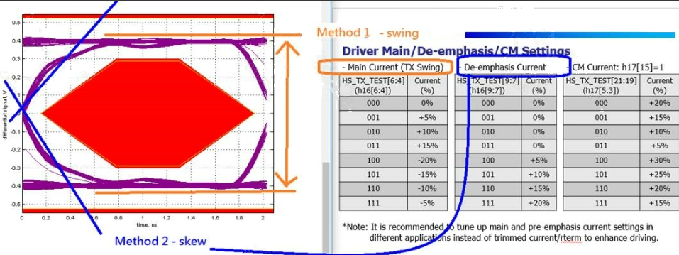
TX swing: As shown in the figure above, it refers to the part marked in yellow, which is mainly for adjusting the eye height (adjustment of the DM DP differential signal Level, which is closest to the USB2 driving capability). If the eye height part of the test results does not meet the requirements, you can provide corresponding modification methods/methods (the higher the intensity is turned on, the more the corresponding eye height is opened)
-
De-emphasis Current: As shown in the figure above, it refers to the part marked in blue, which is mainly for modifying the rising/falling speed of the waveform (de-emphasis design in high-speed signal transmission). If there is a situation where the rising/falling waveform suppresses the eye diagram, you can try to adjust this part (the higher the intensity is turned on, the steeper the corresponding waveform)
7. USB 3.0 PHY Parameter Adjustment
USB 3.0 PHY driver exposes parameter adjustment interfaces through debugfs, at the path /sys/kernel/debug/usb/<device_name>/.
7.1. USB3 PIPE PHY
| Parameter | Description | Range | R/W |
|---|---|---|---|
| tx-idrv | TX drive current | 0~63 (6-bit) | RW |
| tx-idem | TX de-emphasis | 0~63 (6-bit) | RW |
| tx-biasi | TX bias current | 0~7 | RW |
| ssc | SSC enable/disable | 0=disable, 1=enable | RW |
7.2. USB3 SUPPHY
| Parameter | Description | Range | R/W |
|---|---|---|---|
| swing-mode | TX Swing mode selection | 2=Full-Swing, 3=Low-Swing | RW |
| swing-amplitude | TX Low-Swing amplitude level (0=-1.5dB, 1=-2.5dB, 2=-3.5dB, 3=-4.5dB, 4=-6dB, 5=-7.6dB) | 0~5 | RW |
| tx-deemphasis | TX de-emphasis amplitude (0=-6dB, 1=-3.5dB, 2=0dB) | 0~2 | RW |
7.3. DWC3
| Parameter | Description | Range | R/W |
|---|---|---|---|
| ltssm-state | LTSSM state record (requires ENABLE_LTSSM_MONITOR) | - | R |
| compliance-enabled | Compliance Mode enable (Host mode only) | 0 / 1 | W |
8. USB 3.0 Eye Diagram Testing
For USB3.0, eye diagram testing can be performed after entering compliance mode, which requires a high-end oscilloscope to test the USB3.0 eye diagram.
8.1. Device mode
For 3.0 device, when the USB3.0 device is connected to a high-end oscilloscope, it can automatically enter compliance mode.
8.2. Host mode
For 3.0 host, you need to execute the following command after the kernel boots up, and then connect to a high-end oscilloscope to enter compliance mode. Note that the "soc:usb3-p3" below depends on the actual usb3 node name.
9. FAQ
Q1: Unable to recognize USB host connected device under kernel
-
Check if the VBUS power supply has been pulled up
-
Check if the
statusof DTS ehci node isokay -
Check if the kernel config is configured
Q2: High speed devices recognized as full speed in the kernel
- Check if the upper level of the device is connected to the full speed hub
Q3: U-disk upgrade failed under uboot
-
Check if the VBUS power supply has been pulled up
-
Check if the
statusof DTS ehci node isokay -
Check if the USB drive is in FAT32 format
Q4: USB empty chip upgrade failed
-
Check if it is in an empty upgrade state, the serial port will print a log(Start USB Mode) for the empty upgrade state
-
Check if the packaged USB image matches the board
Q5: After configuring it as a USB 3.0 device, it's detected as high speed when connected to the PC
-
Check if the USB cable supports USB 3.0.
-
Check if the UDC is dwc3.
Q6: After configuring as USB3.0, Port2 can only be recognized as High speed
The dtsi default is PCIE0 2x + Port2 USB2.0-only (Port2 works at High speed). To run Port2 at USB3.0 (SuperSpeed), the SUPPHY must be given to Port2 and the DTS fully modified (any missing item keeps it at High speed):
-
Disable PCIE0 (or downgrade to 1x) to give SUPPHY to Port2
-
Set
u3phy_p2_utmi/u3phy_p2_pipe/usb3drd_p2to okay -
Restore dwc3
maximum-speed="super-speed"withphysreferencing utmi+pipe -
Remove
sgs,combo-phy-resetfromusb3drd_p2 -
On the EVB board, the phy is shared with pcie and the signal will be interfered. Rework is required. Please consult CAE for details.