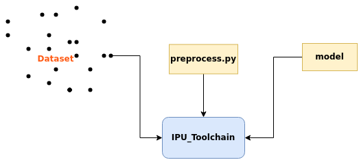
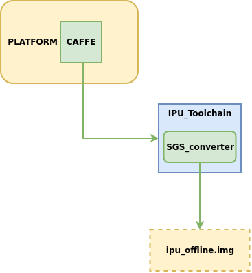
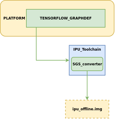
2. 模型转换
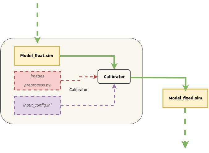
本章主要介绍如何将不同平台的网络模型转换到可供开发板运行的IPU离线网络模型, 模型转换示意图:
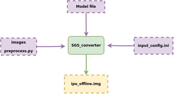
模型转换流程说明:
① 模型文件Model file
② 配置文件 input_config.ini
③ 模型转换所需要的数据images 、前处理脚本preprocess.py
送入模型转换工具SGS_converter,
即可获得可供开发板运行的IPU离线网络模型 img 文件。
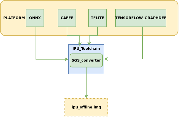
IPU工具链现支持将以下platform的模型转换到离线网络:
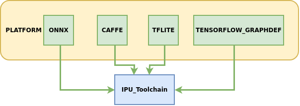
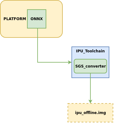
其中ONNX为IPU工具链主力支持的模型框架,可以提供较完整的功能迭代与技术服务支持,其余框架的模型处于维护支持状态,建议优先转换ONNX框架下的模型以获得最佳体验。
下面将详细介绍如何使用IPU Toolchain生成离线模型。
1. 模型转换配置文件——input_config.ini使用指南
各平台模型在转换为IPU离线网络模型的指令中都需使用必选参数 --input_config 用于指定input tensor的配置信息文件input_config.ini路径, 本节主要介绍转换模型过程中所需的input_config.ini文件如何进行配置。
1.1 input config.ini内容概述
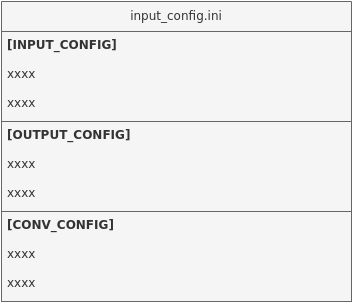
该文件主要分为三部分进行信息的配置:
[INPUT_CONFIG]   # 配置网络模型图片前处理的归一化信息

[OUTPUT_CONFIG]  # 配置网络模型输入输出的量化处理信息

[CONV_CONFIG]    # optional, 配置网络模型中卷积的量化信息
1.2 input config.ini基础使用
配置示例及说明:
[INPUT_CONFIG]

inputs= data;                   # 输入节点名称,多个输入需以“,”隔开

training_input_formats=RGB;     # 模型训练时的输入格式,数量和顺序与`inputs`的配置一致

input_formats=BGR;              # 板端输入格式,数量和顺序与`inputs`的配置一致

quantizations=TRUE;             # 是否打开输入量化, 可选格式为TRUE或者FALSE,数量和顺序与`inputs`的配置一致

mean=127.5:127.5:127.5;         # 均值, 顺序为RGB,多个输入需以“,”隔开

std_value = 255;                # 方差, 多个输入需以“,”隔开,如果每个通道都有对应的`std_value`值,以英文冒号( : )分隔,顺序为RGB

[OUTPUT_CONFIG]

outputs= prob;                  # 输出节点名称,多个输入需以“,”隔开

dequantizations=TRUE;           # 是否开启反量化, 根据实际需求填写, 建议为TRUE,数量和顺序与`outputs`的配置一致

[CONV_CONFIG]                   #  optional

tensor_arrays=conv1-1,conv2-1;  # 指定网络中某些层的卷积量化方式,需要更高的精度时配置。
1.3 input config.ini使用进阶
下面将针对 [INPUT_CONFIG]、[OUTPUT_CONFIG] 和 [CONV_CONFIG] 三部分信息可设置的参数分别进行讲解:
1.3.1 [INPUT_CONFIG]可配置信息详解
1、可配置参数说明
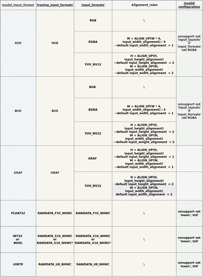
现阶段支持的参数有:inputs、training_input_formats、input_formats、quantizations、mean、std_value、input_width_alignment (optional)、input_height_alignment (optional)、input_layouts (optional)。
(1) inputs: 网络输入Tensor的name。
使用须知
-
多个输入Tensor请用逗号( , )分隔。模型输入Tensor数量和顺序与
inputs的配置一致。 -
所有输入name的长度不能超过2048个字符。
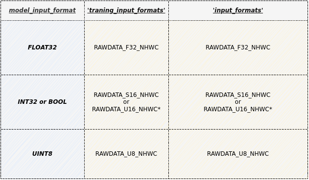
(2) training_input_formats: 网络训练时的图片格式。
使用须知
-
多个输入Tensor请用逗号( , )分隔。模型输入Tensor数量和顺序与
inputs的配置一致。 -
可选格式包括:
- RGB
- BGR
- GRAY
- RAWDATA_U8_NHWC
- RAWDATA_S16_NHWC
- RAWDATA_F32_NHWC
- 各模型推荐配置值详见下节表格
(3) input_formats: 网络模型在IPU芯片上运行的图片输入格式。
使用须知
-
多个输入Tensor请用逗号( , )分隔。模型输入Tensor数量和顺序与
inputs的配置一致。 -
可选格式包括:
- RGB
- BGR
- RGBA
- BGRA
- YUV_NV12
- GRAY
- RAWDATA_U8_NHWC
- RAWDATA_S16_NHWC
- RAWDATA_F32_NHWC
- 各模型推荐配置值详见下节表格
(4) quantizations: 用来标识所有输入Tensor的数据是否需要做量化,TRUE或者FALSE。
使用须知
- 多个输入Tensor请用逗号( , )分隔。模型输入Tensor数量和顺序与
inputs的配置一致。
(5) mean: 网络训练阶段用来对图片进行前处理。
图片做归一化的公式如下: $$ \text{normalized_image} = \frac{\text{original_image} - (\text{mean_R}, \text{mean_G}, \text{mean_B})}{\text{std_value}} $$
使用须知
-
顺序为RGB ,分别代表相应通道上的mean值。
-
数量等于inputs 个数,多个输入Tensor以英文逗号( , )分隔且中间不可有空格。
-
RAWDATA格式的数据请不要配置mean,其余格式如果没有做归一化处理,这个值设为0。
(6) std_value: 网络训练阶段用来对图片进行前处理。
使用须知
-
数量等于inputs 个数, 多个输入Tensor以英文逗号( , )分隔且中间不可有空格。
-
如果每个通道都有对应的
std_value值,以英文冒号( : )分隔,顺序为RGB。 -
RAWDATA格式的数据请不要配置mean,其余格式如果没有做归一化处理,这个值设为0。
(7) input_width_alignment (optional):用来标识数据作为网络输入时Width方向对齐的数量。
使用须知
- 如果有多个输入Tensor,以英文逗号( , )分隔且中间不可有空格。
- 各模型推荐配置值请参考下节表格'Alignment_rules'列
(8) input_height_alignment (optional):用来标识数据作为网络输入时Height方向对齐的数量。
使用须知
- 如果有多个输入Tensor,以英文逗号( , )分隔且中间不可有空格。
- 各模型推荐配置值请参考下节表格'Alignment_rules'列
(9) input_layouts (optional): 用来标识模型输入Tensor的数据排布格式。
使用须知
-
default is NHWC.
-
可选数据排布格式包括:
-
NCHW: 仅对4维输入Tensor生效
-- 4维Tensor处理:当指定NCHW时,强制按NCHW排布。
-- 非4维Tensor处理:维度输入保持原状,但需在input_layouts中用NHWC占位
-
NHWC: 仅对4维输入Tensor生效
-- 4维Tensor处理:当指定NHWC时,强制按NHWC排布。
-- 非4维Tensor处理:维度输入保持原状,但需在input_layouts中用NHWC占位
-
-
数量等于inputs个数,模型输入Tensor顺序与
input_layouts的配置顺序一致, 多个输入Tensor以英文逗号(,)分隔且中间不可有空格。 -
注意:当4维输入的
input_layouts设为NCHW时,需要确保该输入对应的前处理脚本(下节给出介绍)返回数据也按照NCHW排布,且板端运行离线模型时的输入数据排布也按照NCHW排布。 -
注意:当input_formats设定为YUV_NV12的输入的
input_layouts被设为NCHW时,需要确保该输入对应的前处理脚本(下节给出介绍)返回数据也按照NCHW排布,而在板端运行离线模型时的输入数据为正常排布的YUV_NV12。 -
注意:当input_formats设定为RGBA、BGRA时,不支持指定对应输入的
input_layouts。
2、模型参数配置约束条件与选择组合
使用须知
-
RAWDATA_U16_NHWC :仅限于输入直接接embedding层的情况,
例如:CLIP Text模型的embedding层
其embeeeding 层的index 满足 32727 < index < 65535 的条件时,可以配置成 RAWDATA_U16_NHWC。
使用须知
-
灰度模型转换须知:
-
input_formats为GRAY时:实际给Fixed或Offline模型的数据为灰度图片,此时对应的[INPUT_CONFIG] ...... training_input_formats=GRAY; input_formats=GRAY; ......input_width_alignment和input_height_alignment默认为1,如不设定input_width_alignment和input_height_alignment,实际输入与模型输入形状相同。 -
input_formats为YUV_NV12时:实际给Fixed或Offline模型的数据为YUV_NV12数据,此时对应的[INPUT_CONFIG] ...... training_input_formats=GRAY; input_formats=YUV_NV12; ......input_width_alignment和input_height_alignment默认为2。 -
input_config.ini文件中仅需设置单通道的mean值
[INPUT_CONFIG]
......
mean=33.318;
std_value=1.0;
-
3、多输入模型配置注意事项:
(1) 当模型存在多输入且数据格式混合时,若包含rawdata格式输入,需注意:
使用须知
-
1)禁止为rawdata格式输入配置mean/std归一化参数;
-
2)在ini配置文件中必须将rawdata输入排列在最后一位。
如: input_list = [input0,input1,input2] , 其中input0和input2为RGB格式,input1为RAWDATA格式,请在ini中按照 [inpit0,input2,input1]的顺序进行输入配置:
[INPUT_CONFIG]
inputs=input0,input2,input1;        # 调整输入顺序,RAWDATA格式tensor置后。
input_formats=RGB,RGB,RAWDATA_F32_NHWC;
quantizations=TRUE,TRUE,TRUE;
mean=127.5:127.5:127.5,0:0:0;       #只配置两组,input1禁止配置归一化参数
std_value = 255,255;                # 只配置两组,input1禁止配置归一化参数
(2) 当模型存在多输入且数据维度混合时,若需配置 input_layouts ,需注意:
使用须知
- 1) 非4维Tensor需在input_layouts中用NHWC占位。
如: input_list = [input0,input1,input2] , 其中input0为3维tensor,input1和input2为4维tensor,指定input1按照NCHW进行排布:
[INPUT_CONFIG]
inputs=input0,input1,input2;

…

input_layouts=NHWC,NCHW,NHWC;       # input0为非4维tensor,需要配置占位
1.3.2 [OUTPUT_CONFIG]可配置信息详解
现阶段支持的参数有:outputs、dequantizations、output_layouts (optional)、output_formats (optional)。
(1) outputs: 网络输出节点名称。
使用须知
-
多个输出Tensor以英文逗号( , )分隔,顺序与模型保持一致。
-
所有输出name的长度不能超过2048个字符。
-
转换带后处理网络时,Backbone网络的outputs与完整网络outputs的名称不同,其余设置应完全一致。
(2) dequantizations: 用来标识所有输出Tensor的数据是否需要做反量化,TRUE或者FALSE。
使用须知
-
仅在板上运行时生效,数量等于outputs,输出Tensor以英文逗号( , )分隔且中间不可有空格。
-
如果配置
dequantizations为TRUE,模型输出会增加Fix2Float算子,输出数据类型为float32。 -
如果配置
dequantizations为FALSE,在板端运行时输出数据类型为int16。
(3) output_layouts (optional): 用来标识输出Tensor的数据排布格式。
使用须知
-
如果不设置该项,将默认数据排布格式为
NHWC。 -
可选数据排布格式包括:
- NCHW:
NCHW表示对应的4维outputTensor按照NCHW的数据格式排布。 - NHWC:
NHWC表示对应的4维outputTensor按照NHWC的格式排布。
- NCHW:
-
数量等于outputs个数,模型输出Tensor顺序与
output_layouts的配置顺序一致,多个输入Tensor以英文逗号(,)分隔且中间不可有空格。
(4) output_formats (optional): 标识输出Tensor的数据格式。
使用须知
-
如果不设置该项,将默认数据格式以
dequantizations的配置为准:当dequantizations为TRUE时,输出RAWDATA_F32_NHWC;当dequantizations为FALSE时,输出RAWDATA_S16_NHWC,且不会反量化。 -
可选数据格式包括:
- RAWDATA_F32_NHWC: 模型输出float32类型数据。
dequantizations只能配置TRUE。 - RAWDATA_S16_NHWC: 模型输出int16类型数据。当
dequantizations为TRUE时,输出int16会反量化回真实数值;当dequantizations为FALSE时,输出int16不会反量化。 - RAWDATA_U8_NHWC: 模型输入uint8类型数据。当
dequantizations为TRUE时,输出uint8会反量化回真实数值;当dequantizations为FALSE时,输出uint8不会反量化。
- RAWDATA_F32_NHWC: 模型输出float32类型数据。
-
如果有多个输出Tensor,以英文逗号(,)分隔且中间不可有空格。数量等于outputs个数,模型输出Tensor顺序与
output_formats的配置顺序一致。
1.3.3 [CONV_CONFIG] (optional)可配置信息详解
此部分均为非必须配置的参数,现阶段支持的参数有:input_format (optional)、input_format (optional)。
(1) input_format (optional): 指定网络中所有卷积的量化方式。
使用须知
-
转换工具默认使用IPU Toolchain推荐的量化方式,还可以通过配置input_format指定量化。可选方案有:
ALL_UINT8: 指定所有卷积按照UINT8量化。ALL_INT16: 指定所有卷积按照INT16量化。CONV2D_INT16: 只指定所有普通卷积按照INT16量化。DEPTHWISE_INT16: 只指定所有Depthwise 卷积按照INT16量化。
-
在
ALL_UINT8 模式下,卷积运行所占带宽小,运行速度快;在ALL_INT16 模式下,可以极大的提高卷积的精度,但是运行的速度会有影响。 -
配置了
input_format后,使用calibrator/torch_calibrator推荐的量化策略将失效。如果要使用calibrator/torch_calibrator推荐的量化策略,需要删除input_format后重新转换模型。
(2) tensor_arrays (optional): 指定网络中某些层的卷积量化方式。
使用须知
-
转换工具默认使用IPU Toolchain推荐的量化方式,某些卷积层需要更高的精度时可以配置'tensor_arrays'实现指定部分卷积层量化方式。
-
填写卷积层的第一个输入的 input tensor name。需要配置多个卷积层更高精度时,input tensor name以逗号( , )分隔。
-
指定量化时,网络中的第一层卷积不生效。
2. 模型转换配置文件——前处理脚本书写指南
各平台模型在转换为IPU离线网络模型的指令中都需使用必选参数 -n 指定前处理脚本路径,本节主要介绍转换模型过程中所需的前处理文件如何进行配置。
2.1 前处理文件编写示例
以onnx_yolov8s网络为例,对编写图片前处理文件进行说明,demo展示:
import cv2
import numpy as np

def letterbox(im, new_shape=(640, 640), color=(114, 114, 114), auto=False, scaleFill=False, scaleup=True, stride=32):
    # Resize and pad image while meeting stride-multiple constraints
    shape = im.shape[:2]  # current shape [height, width]
    if isinstance(new_shape, int):
        new_shape = (new_shape, new_shape)

    # Scale ratio (new / old)
    r = min(new_shape[0] / shape[0], new_shape[1] / shape[1])
    if not scaleup:  # only scale down, do not scale up (for better val mAP)
        r = min(r, 1.0)

    # Compute padding
    ratio = r, r  # width, height ratios
    new_unpad = int(round(shape[1] * r)), int(round(shape[0] * r))
    dw, dh = new_shape[1] - new_unpad[0], new_shape[0] - new_unpad[1]  # wh padding
    if auto:  # minimum rectangle
        dw, dh = np.mod(dw, stride), np.mod(dh, stride)  # wh padding
    elif scaleFill:  # stretch
        dw, dh = 0.0, 0.0
        new_unpad = (new_shape[1], new_shape[0])
        ratio = new_shape[1] / shape[1], new_shape[0] / shape[0]  # width, height ratios

    dw /= 2  # divide padding into 2 sides
    dh /= 2

    if shape[::-1] != new_unpad:  # resize
        im = cv2.resize(im, new_unpad, interpolation=cv2.INTER_LINEAR)
    top, bottom = int(round(dh - 0.1)), int(round(dh + 0.1))
    left, right = int(round(dw - 0.1)), int(round(dw + 0.1))
    im = cv2.copyMakeBorder(im, top, bottom, left, right, cv2.BORDER_CONSTANT, value=color)  # add border
    return im, ratio, (dw, dh)


def image_preprocess(image_file, norm=True, new_shape=(640, 640)):
    im = cv2.imread(image_file)

    im, ratio, (dw, dh) = letterbox(im, new_shape)

    im = im[:, :, ::-1]  # BGR to RGB
    im = np.expand_dims(im, 0)
    im = np.ascontiguousarray(im)
    if norm:
        return im.astype(np.float32) / 255
    else:
        return im
使用须知
-
需要声明
image_preprocess(img_path, norm=True)的函数原型来调用,函数返回numpy.ndarray的数据类型。 -
当模型的training_input_formats为RGB / BGR / GRAY时,
image_preprocess(img_path, norm=True)函数必须包含的2个参数:-
图片路径
-
归一化标记(norm=True)
归一化标记是为了区分网络模型是否是浮点模型。因为在浮点网络模型阶段,图片的归一化需要在送进网络前处理好。但是定点网络模型和离线网络模型已经包含了input_config.ini文件的设置信息,能够将图片数据自行做归一化处理,因此送进网络模型的数据不需要做归一化,这与在IPU硬件上处理方式相同。
-
-
前处理文件对输入数据的处理要与模型训练时保持一致,前处理脚本是将数据文件处理成为模型的
training_input_formats的格式。
2.2 前处理文件编写说明
不同数据格式的前处理略有不同,下面将分别给出示例:
① 图片输入模型前处理说明
适用于training_input_formats为RGB / BGR / GRAY的模型。
图片输入模型的前处理脚本用户主要关心将数据文件处理成为模型的training_input_formats的格式。
以torchvision的resnet18前处理脚本示例:
from PIL import Image
import numpy as np
from torchvision.transforms import transforms

def sim_standard_preprocess(image_file, input_size=224, norm=True):
    ori_image = Image.open(image_file).convert('RGB')
    if input_size == 299:
        scaled_size = input_size
    else:
        scaled_size = 256
    image = transforms.Resize(scaled_size)(ori_image)
    image = transforms.CenterCrop(input_size)(image)
    if norm:
        image = transforms.Compose(
            [
                transforms.ToTensor(),
                transforms.Normalize(mean=[0.485, 0.456, 0.406], std=[0.229, 0.224, 0.225])
            ]
        )(image)
        image = image.numpy()
        image = np.expand_dims(image, 0).astype(np.float32)
        image = np.transpose(image, axes=(0, 2, 3, 1)).copy()
    else:
        image = image.numpy()
        image = np.expand_dims(image, 0).astype(np.uint8)
    return image


def image_preprocess(image_file, input_size=224, norm=True):
    sim_processed = sim_standard_preprocess(image_file, input_size, norm=norm)
    return sim_processed
使用须知
-
针对图片做归一化的公式,上述mean/std信息转换到input_config.ini时是:
[INPUT_CONFIG] mean=123.675:116.28:103.53; std_value=58.395:57.12:57.375; -
使用时务必检查前处理脚本中的mean和std参数与input_config.ini中配置的信息保持等价。
以caffe的caffe_lenet前处理脚本示例GRAY输入的模型:
import cv2
import numpy as np

def get_image(img_path, resizeH=28, resizeW=28, norm=True, mean=33.318, std=1.0):
    img = cv2.imread(img_path)
    if img is None:
        raise FileNotFoundError('No such image: {}'.format(img_path))

    img = cv2.cvtColor(img, cv2.COLOR_BGR2GRAY)
    img_norm = cv2.resize(img, (resizeW, resizeH), interpolation=cv2.INTER_LINEAR)

    if norm:
        img_norm = (img_norm - mean) / std
        img_norm = np.expand_dims(img_norm, axis=2)
        img_norm = img_norm.astype('float32')
    else:
        img_norm = np.expand_dims(img_norm, axis=2)

    return np.expand_dims(img_norm, 0)

def image_preprocess(img_path, norm=True):
    return get_image(img_path, norm=norm)
② 非图片输入模型前处理示例
示例输入数据是保存的npy文件。实际使用请替换真实处理逻辑。
非图片输入模型用户对float / fixed / offline模型的输入数据格式都要考虑。当norm为True时返回float模型需要的格式,当norm为False时,返回fixed / offline模型需要的格式。
float模型一般与原始模型输入的数据格式一致。
1) 适用于training_input_formats和input_formats均为RAWDATA_F32_NHWC的模型。
前处理脚本示例:
import numpy as np

def image_preprocess(img_path, norm=True):
    data = np.load(img_path)    # img_path is npy file, contains float32 dtype ndarray
    data = data.astype(np.float32)
    return data

def image_preprocess(img_path, norm=True):
    return get_image(img_path, norm=norm)
2) 适用于training_input_formats和input_formats均为RAWDATA_S16_NHWC的模型。
前处理脚本示例:
import numpy as np

def image_preprocess(img_path, norm=True):
    data = np.load(img_path)    # img_path is npy file, contains int32 or bool dtype ndarray
    if norm:
        data = data.astype(np.int32)    # or astype(np.bool_) / astype(np.float32) ……
    else:
        data = data.astype(np.int16)
    return data


def image_preprocess(img_path, norm=True):
    return get_image(img_path, norm=norm)
3) 适用于training_input_formats和input_formats均为RAWDATA_U16_NHWC的模型。
使用须知
-
RAWDATA_U16_NHWC :仅限于输入直接接embedding层的情况,
例如:CLIP Text模型的embedding层
其embeeeding 层的index 满足 32727 < index < 65535 的条件时,可以配置成 RAWDATA_U16_NHWC。
前处理脚本示例:
import numpy as np

def image_preprocess(img_path, norm=True):
    data = np.load(img_path)    # img_path is npy file, contains int32 dtype ndarray
    if norm:
        data = data.astype(np.int32)
    else:
        data = data.astype(np.uint16)
    return data


def image_preprocess(img_path, norm=True):
    return get_image(img_path, norm=norm)
4) 适用于training_input_formats和input_formats均为RAWDATA_U8_NHWC的模型。
前处理脚本示例:
import numpy as np

def image_preprocess(img_path, norm=True):
    data = np.load(img_path)    # img_path is npy file, contains uint8 dtype ndarray
    if norm:
        data = data.astype(np.uint8)
    else:
        data = data.astype(np.uint8)
    return data

def image_preprocess(img_path, norm=True):
    return get_image(img_path, norm=norm)
3. 原始模型到端侧模型转换指南
IPU Toolchain的SGS_converter工具支持一键生成可供开发板运行的IPU离线网络模型。
3.1. SGS_converter工具简介
1、工具位置:SGS_IPU_Toolchain/Scripts/ConvertTool/SGS_converter.py.
2、工具作用:将模型一键转换为SGS离线网络模型。
3、使用示例:
以转换ONNX框架的模型到离线网络为例:
python3 ~/SGS_IPU_Toolchain/Scripts/ConvertTool/SGS_converter.py onnx
--model_file  ~/SGS_Models/onnx/onnx_yolov8s/onnx_yolov8s.onnx \
--input_config ~/SGS_Models/onnx/onnx_yolov8s/input_config.ini \
-i ~/SGS_Models/resource/classify/ILSVRC2012_test_00000002.bmp \
-n ~/SGS_Models/onnx/onnx_yolov8s/onnx_yolov8s.py \
--output_file ./onnx_yolov8s_offline.img \
--soc_version CHIP
不同平台模型转换为SGS离线网络模型的所需参数信息略有不同,如果想进一步了解各个平台转换所需要的参数信息(关于参数的使用说明将在下文给出),可以执行
python3 SGS_converter.py {platform} –h
进行查看。
如查看CAFFE框架的执行参数:
python3 SGS_converter.py caffe –h
3.2 SGS_converter工具使用详解
本节主要介绍使用SGS_converter工具转换各platform的模型时,如何进行参数配置。
3.2.1 转换ONNX模型
1、 工具使用示例:
python3 ~/SGS_IPU_Toolchain/Scripts/ConvertTool/SGS_converter.py onnx
--model_file  ~/SGS_Models/onnx/onnx_yolov8s/onnx_yolov8s.onnx \
--input_config ~/SGS_Models/onnx/onnx_yolov8s/input_config.ini \
-i ~/SGS_Models/resource/classify/ILSVRC2012_test_00000002.bmp
-n ~/SGS_Models/onnx/onnx_yolov8s/onnx_yolov8s.py \
--output_file ./onnx_yolov8s_offline.img \
--export_models \
--soc_version CHIP
(1) 必选参数:
-
--model_file: 指定需进行转换的ONNX模型文件路径。 -
--input_config: input_config.ini文件路径。 -
-i: 输入文件 / 输入文件夹路径 / 指定输入路径列表文件 。
使用须知
-
-i参数传入 指定输入路径列表文件 的形式时:新建input_list.txt,新增内容如下:
-
网络模型为单输入时:
/path/to/image_test/2007000364.jpg /path/to/image_test/2007000365.jpg /path/to/image_test/2007000366.jpg -
网络模型为多输入时,用英文逗号(
,)分割每个输入的路径:/path/to/image_test/2007000364.jpg,/path/to/image_test/ILSVRC2012_test_00000002.bmp /path/to/image_test/2007000365.jpg,/path/to/image_test/ILSVRC2012_test_00000003.bmp /path/to/image_test/2007000366.jpg,/path/to/image_test/ILSVRC2012_test_00000004.bmp
有多组数据可以写在下一行,读取时认为每行是模型的一次输入数据。完成input_list.txt后
-i 参数为: /path/to/input_list.txt
-
-
当
-i/--image的参数为单张图片的路径时,模型只能为单输入模型。 -
当
-i/--image的参数为图片文件夹的路径时,模型只能是单输入模型,会对文件夹内的数据全部读取。
-n: 前处理Python的文件路径。
使用须知
-
多输入模型的前处理参数需使用多个前处理方法,前处理Python文件路径的个数和顺序需与模型输入个数和顺序保持一致。例如:
-n /path/to/preprocess1.py,/path/to/preprocess2.py 或者 --preprocess /path/to/preprocess1.py,/path/to/preprocess2.py
-
请使用与训练相同的图片前处理方式,每个输入的前处理方式需独立编写python文件。
-
--output_file: 指定生成的img文件名称。 -
--soc_version: IPU Toolchain chip
使用须知
- 执行python3 SGS_IPU_Toolchain/DumpDebug/show_sdk_info.py 可查看IPU Toolchain具体适配那些chip及版本信息
(2) 可选参数:
-
--export_models: 指定模型生成中间结果的模型文件,不配置则只生成离线文件。 -
-q: 当使用torch_calibrator量化float模型时,需要制定此参数。 -
--quant_config: 当设置-q参数时,需要通过此参数传入quant_config.yaml量化参数文件。
使用须知
如果onnx模型中带有后处理的算子,请先去除,目前只支持主干网络的转换。如果是由其他框架生成的onnx模型,请务必注意在转换模型时关闭生成后处理的选项。
3.2.2 转换CAFFE模型
1、 工具使用示例:
python3 ~/SGS_IPU_Toolchain/Scripts/ConvertTool/SGS_converter.py onnx
--model_file  ~/SGS_Models/caffe/caffe_mobilenet_v2/caffe_mobilenet_v2.prototxt \
--weight_file ~/SGS_Models/caffe/caffe_mobilenet_v2/caffe_mobilenet_v2.caffemodel \
--input_config ~/SGS_Models/caffe/caffe_mobilenet_v2/input_config.ini \
-i ~/SGS_Models/resource/classify/ILSVRC2012_test_00000002.bmp \
-n ~/SGS_Models/caffe/caffe_mobilenet_v2/caffe_mobilenet_v2.py \
--output_file ./caffe_mobilenet_v2.img \
--export_models \
--soc_version CHIP
(1) 必选参数:
-
--model_file: 指定需进行转换的CAFFE模型文件路径。 -
--weight_file: 指定需进行转换的CAFFE权重文件路径。 -
--input_config: input_config.ini文件路径。 -
-i: 输入文件 / 输入文件夹路径 / 指定输入路径列表文件 。
使用须知
-
-i参数传入 指定输入路径列表文件 的形式时:新建input_list.txt,新增内容如下:
-
网络模型为单输入时:
/path/to/image_test/2007000364.jpg /path/to/image_test/2007000365.jpg /path/to/image_test/2007000366.jpg -
网络模型为多输入时,用英文逗号(
,)分割每个输入的路径:/path/to/image_test/2007000364.jpg,/path/to/image_test/ILSVRC2012_test_00000002.bmp /path/to/image_test/2007000365.jpg,/path/to/image_test/ILSVRC2012_test_00000003.bmp /path/to/image_test/2007000366.jpg,/path/to/image_test/ILSVRC2012_test_00000004.bmp
有多组数据可以写在下一行,读取时认为每行是模型的一次输入数据。完成input_list.txt后
-i 参数为: /path/to/input_list.txt
-
-
当
-i/--image的参数为单张图片的路径时,模型只能为单输入模型。 -
当
-i/--image的参数为图片文件夹的路径时,模型只能是单输入模型,会对文件夹内的数据全部读取。
-n: 前处理Python的文件路径。
使用须知
-
多输入模型的前处理参数需使用多个前处理方法,前处理Python文件路径的个数和顺序需与模型输入个数和顺序保持一致。例如:
-n /path/to/preprocess1.py,/path/to/preprocess2.py 或者 --preprocess /path/to/preprocess1.py,/path/to/preprocess2.py
-
请使用与训练相同的图片前处理方式,每个输入的前处理方式需独立编写python文件。
-
--output_file: 指定生成的img文件名称。 -
--soc_version: IPU Toolchain chip
使用须知
- 执行python3 SGS_IPU_Toolchain/DumpDebug/show_sdk_info.py 可查看IPU Toolchain具体适配那些chip及版本信息
(2) 可选参数:
-
--export_models: 指定模型生成中间结果的模型文件,不配置则只生成离线文件。 -
-q: 当使用torch_calibrator量化float模型时,需要制定此参数。 -
--quant_config: 当设置-q参数时,需要通过此参数传入quant_config.yaml量化参数文件。
3.2.3 转换TFLITE模型

1、 工具使用示例:
python3 SGS_converter.py tflite \
--model_file Debug_save_model_float.tflite \
--input_config input_config.ini \
-i file.list \
-n preprocess.py \
--output_file save_model.img \
--soc_version CHIP
(1) 必选参数:
-
--model_file: 指定需进行转换的TFLITE模型文件路径。 -
--input_config: input_config.ini文件路径。 -
-i: 输入文件 / 输入文件夹路径 / 指定输入路径列表文件 。
使用须知
-
-i参数传入 指定输入路径列表文件 的形式时:新建input_list.txt,新增内容如下:
-
网络模型为单输入时:
/path/to/image_test/2007000364.jpg /path/to/image_test/2007000365.jpg /path/to/image_test/2007000366.jpg -
网络模型为多输入时,用英文逗号(
,)分割每个输入的路径:/path/to/image_test/2007000364.jpg,/path/to/image_test/ILSVRC2012_test_00000002.bmp /path/to/image_test/2007000365.jpg,/path/to/image_test/ILSVRC2012_test_00000003.bmp /path/to/image_test/2007000366.jpg,/path/to/image_test/ILSVRC2012_test_00000004.bmp
有多组数据可以写在下一行,读取时认为每行是模型的一次输入数据。完成input_list.txt后
-i 参数为: /path/to/input_list.txt
-
-
当
-i/--image的参数为单张图片的路径时,模型只能为单输入模型。 -
当
-i/--image的参数为图片文件夹的路径时,模型只能是单输入模型,会对文件夹内的数据全部读取。
-n: 前处理Python的文件路径。
使用须知
-
多输入模型的前处理参数需使用多个前处理方法,前处理Python文件路径的个数和顺序需与模型输入个数和顺序保持一致。例如:
-n /path/to/preprocess1.py,/path/to/preprocess2.py 或者 --preprocess /path/to/preprocess1.py,/path/to/preprocess2.py
-
请使用与训练相同的图片前处理方式,每个输入的前处理方式需独立编写python文件。
-
--output_file: 指定生成的img文件名称。 -
--soc_version: IPU Toolchain chip
使用须知
- 执行python3 SGS_IPU_Toolchain/DumpDebug/show_sdk_info.py 可查看IPU Toolchain具体适配那些chip及版本信息
(2) 可选参数:
-
--export_models: 指定模型生成中间结果的模型文件,不配置则只生成离线文件。 -
-q: 当使用torch_calibrator量化float模型时,需要制定此参数。 -
--quant_config: 当设置-q参数时,需要通过此参数传入quant_config.yaml量化参数文件。
3.2.4 转换TENSORFLOW_GRAPHDEF模型
1、 工具使用示例:
python3 SGS_converter.py tensorflow_graphdef \
--graph_def_file yolo_v3_7/yolo_v3_7.pb \
--input_config input_config.ini \
--input_shapes 1,299,299,3 \
-i file.list \
-n yolo_v3_7.py \
--output_file yolo_v3_7.img \
--soc_version CHIP
(1) 必选参数:
-
--graph_def_file: 指定需进行转换的模型文件路径。 -
--input_config: input_config.ini文件路径。 -
--input_shapes: 指定网络输入Tensor的shape,shape个数和inputs个数对应,多个shape之间以冒号( : )分隔 -
-i: 输入文件 / 输入文件夹路径 / 指定输入路径列表文件 。
使用须知
-
-i参数传入 指定输入路径列表文件 的形式时:新建input_list.txt,新增内容如下:
-
网络模型为单输入时:
/path/to/image_test/2007000364.jpg /path/to/image_test/2007000365.jpg /path/to/image_test/2007000366.jpg -
网络模型为多输入时,用英文逗号(
,)分割每个输入的路径:/path/to/image_test/2007000364.jpg,/path/to/image_test/ILSVRC2012_test_00000002.bmp /path/to/image_test/2007000365.jpg,/path/to/image_test/ILSVRC2012_test_00000003.bmp /path/to/image_test/2007000366.jpg,/path/to/image_test/ILSVRC2012_test_00000004.bmp
有多组数据可以写在下一行,读取时认为每行是模型的一次输入数据。完成input_list.txt后
-i 参数为: /path/to/input_list.txt
-
-
当
-i/--image的参数为单张图片的路径时,模型只能为单输入模型。 -
当
-i/--image的参数为图片文件夹的路径时,模型只能是单输入模型,会对文件夹内的数据全部读取。
-n: 前处理Python的文件路径。
使用须知
-
多输入模型的前处理参数需使用多个前处理方法,前处理Python文件路径的个数和顺序需与模型输入个数和顺序保持一致。例如:
-n /path/to/preprocess1.py,/path/to/preprocess2.py 或者 --preprocess /path/to/preprocess1.py,/path/to/preprocess2.py
-
请使用与训练相同的图片前处理方式,每个输入的前处理方式需独立编写python文件。
-
--output_file: 指定生成的img文件名称。 -
--soc_version: IPU Toolchain chip
使用须知
- 执行python3 SGS_IPU_Toolchain/DumpDebug/show_sdk_info.py 可查看IPU Toolchain具体适配那些chip及版本信息
(2) 可选参数:
-
--export_models: 指定模型生成中间结果的模型文件,不配置则只生成离线文件。 -
-q: 当使用torch_calibrator量化float模型时,需要制定此参数。 -
--quant_config: 当设置-q参数时,需要通过此参数传入quant_config.yaml量化参数文件。
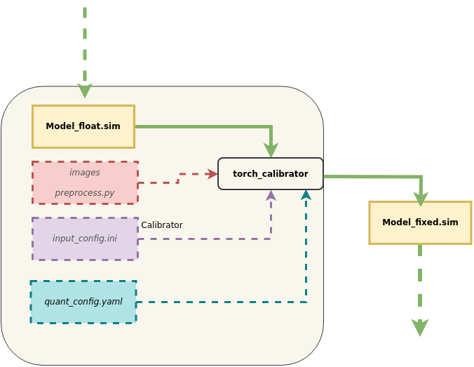
4. 模型转换进阶指南:阶段式生成端侧模型
SGS_converter工具用于一键生成端侧模型,本节主要介绍分步生成端侧模型的方式。流程如图所示:
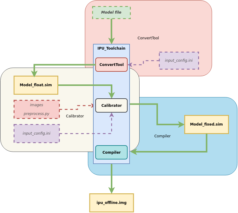
主要分为三个阶段:
Model ——> ConvertTool工具 ——> 浮点网络模型

            ——> Calibrator工具 ——> 定点网络模型

                ——> Compiler工具 ——> 离线网络模型 (端侧模型)
下面分别介绍每个阶段网络生成工具的使用方法。
4.1. 阶段一:ConvertTool工具生成浮点网络模型
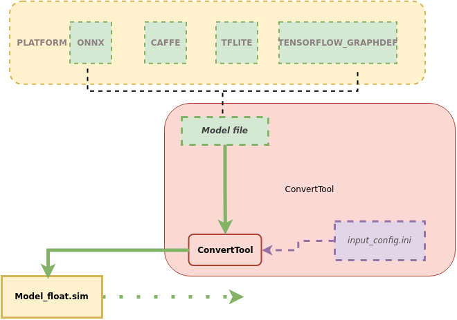
本节介绍如何使用ConvertTool工具将原始模型转换到SGS浮点网络模型。
1、工具位置:SGS_IPU_Toolchain/Scripts/ConvertTool/ConvertTool.py.
2、工具作用:将模型转换为SGS浮点网络模型。
3、使用示例:
以转换ONNX框架的模型到浮点网络为例:
python3 ~/SGS_IPU_Toolchain/Scripts/ConvertTool/ConvertTool.py onnx
--model_file  ~/SGS_Models/onnx/onnx_yolov8s/onnx_yolov8s.onnx \
--input_config ~/SGS_Models/onnx/onnx_yolov8s/input_config.ini \
--output_file ./onnx_yolov8s_float.sim \
--soc_version CHIP
不同平台模型转换为SGS浮点网络模型的所需参数信息略有不同,如果想进一步了解各个平台转换所需要的参数信息(关于参数的使用说明将在下文给出),可以执行
python3 ConvertTool.py {platform} –h
进行查看。
如查看CAFFE框架的执行参数:
python3 ConvertTool.py caffe –h
4.1.1 转换ONNX模型
1、 工具使用示例:
python3 ~/SGS_IPU_Toolchain/Scripts/ConvertTool/ConvertTool.py onnx
--model_file  ~/SGS_Models/onnx/onnx_yolov8s/onnx_yolov8s.onnx \
--input_config ~/SGS_Models/onnx/onnx_yolov8s/input_config.ini \
--output_file ./onnx_yolov8s_float.sim \
--soc_version CHIP
-
--model_file: 指定需进行转换的Onnx模型文件的路径。 -
--input_config: input_config.ini文件路径。 -
--output_file: 转换模型的输出路径。 -
--soc_version: IPU Toolchain chip
使用须知
- 执行python3 SGS_IPU_Toolchain/DumpDebug/show_sdk_info.py 可查看IPU Toolchain具体适配那些chip及版本信息
(2) 可选参数:
-
--input_shapes: Onnx模型输入shape.dimentions 之间以逗号( , )分隔,shape个数和inputs 个数对应,多个shape之间以冒号( : )分隔。
默认从模型信息读取,如果输入为动态分辨率,则必须指定具体的shape。 -
--skip_simplify: 跳过使用onnxsim优化模型,建议使用优化。默认使用onnxsim优化模型,配置该项则跳过优化。
使用须知
1.如果onnx模型中带有后处理的算子,请先去除,目前只支持主干网络的转换。
-
如果是由其他框架生成的onnx模型,请务必注意在转换模型时关闭生成后处理的选项。
-
onnx裁剪模型语句:
onnx.utils.extract_model(input_path, output_path, input_names, output_names, check_model=True)
onnx.utils.extract_model参数说明:
input_path (str | os.PathLike): 原始ONNX模型路径。
output_path (str | os.PathLike): 保持裁剪ONNX模型的路径
input_names (list of string): 裁剪模型输入tensor名字。
output_names (list of string): 裁剪模型输出tensor名字。
check_model (bool): 是否对裁剪模型运行模型检查(默认为True)。
4.1.2 转换CAFFE模型
1、 工具使用示例:
python3 ~/SGS_IPU_Toolchain/Scripts/ConvertTool/ConvertTool.py caffe \
--model_file ~/SGS_Models/caffe/caffe_resnet50_conv/caffe_resnet50_conv.prototxt \
--weight_file ~/SGS_Models/caffe/caffe_resnet50_conv/caffe_resnet50_conv.caffemodel \
--input_config ~/SGS_Models/caffe/caffe_resnet50_conv/input_config.ini \
--output_file ./resnet50_float.sim \
--soc_version CHIP
(1) 必选参数:
-
--model_file: 指定需进行转换的caffe模型文件路径。 -
--weight_file: 指定需进行转换的caffe权重文件路径。 -
--input_config: input_config.ini文件路径,该文件为input config的配置信息。 -
--output_file: 转换模型的输出路径。 -
--soc_version: IPU Toolchain chip
使用须知
- 执行python3 SGS_IPU_Toolchain/DumpDebug/show_sdk_info.py 可查看IPU Toolchain具体适配那些chip及版本信息
(2) 可选参数:
无。
4.1.3 转换TFLITE模型
1、 工具使用示例:
python3 SGS_converter.py tflite \
--model_file Debug_save_model_float.tflite \
--input_config input_config.ini \
--output_file save_model.img \
--soc_version CHIP
-
--model_file: 指定需进行转换的模型文件路径。输入的模型为tflite格式文件路径(必须为非量化模型)。
-
--output_file: 指定输出的模型文件。flatbuffer格式,sim后缀文件。
-
--input_config: input_config.ini文件路径。该文件为input tensor的配置信息。
-
--soc_version: IPU Toolchain chip
使用须知
- 执行python3 SGS_IPU_Toolchain/DumpDebug/show_sdk_info.py 可查看IPU Toolchain具体适配那些chip及版本信息
(2) 可选参数:
- 无。
4.1.4 转换TENSORFLOW_GRAPHDEF模型
1、 工具使用示例:
python3 ConvertTool.py tensorflow_graphdef \
--graph_def_file ~/SGS_Models/tensorflow/resnet_v2_50/resnet_v2_50.pb \
--output_file ./resnet_v2_float.sim \
--input_shapes 1,299,299,3 \
--input_config ~/SGS_Models/tensorflow/resnet_v2_50/input_config.ini\
--soc_version CHIP
(1) 必选参数:
-
--graph_def_file: 指定需进行转换的输入模型路径。为TensorFlow frozen的graphdef的pb格式文件路径。
-
--output_file: 指定生成的浮点网络模型文件名。flatbuffer格式,需以sim后缀命名文件。
-
--input_shapes: 指定网络输入Tensor的shape。格式为NHWC,dimention 之间以逗号( , )分隔;需注意shape个数和inputs个数对应,多个shape之间以冒号( : )分隔。
-
--input_config: input_config.ini文件路径。该文件为input tensor的配置信息。
-
--soc_version: IPU Toolchain chip
使用须知
- 执行python3 SGS_IPU_Toolchain/DumpDebug/show_sdk_info.py 可查看IPU Toolchain具体适配那些chip及版本信息
(2) 可选参数:
- 无。
4.2. 阶段二:Calibrator工具生成定点网络模型
4.2.1 Calibrator工具详解
本节介绍如何使用Calibrator工具将SGS浮点网络模型转换到SGS定点网络模型。
1、工具位置:SGS_IPU_Toolchain/Scripts/calibrator/calibrator.py.
2、工具作用:将模型转换为SGS定点网络模型。
3、使用示例:
以上一节转换的ONNX浮点模型为例:
python3 ~/SGS_IPU_Toolchain/Scripts/calibrator/calibrator.py
--model_file  ~/SGS_Models/onnx/onnx_yolov8s/onnx_yolov8s_float.sim \
--input_config ~/SGS_Models/onnx/onnx_yolov8s/input_config.ini \
-i ~/SGS_Models/resource/classify/ILSVRC2012_test_00000002.bmp
-n ~/SGS_Models/onnx/onnx_yolov8s/onnx_yolov8s.py \
--soc_version CHIP
Calibrator工具可以支持多数模型的转换,少部分模型(如分段网络faste-rcnn)需自行实现Calibrator。
4、Calibrator参数说明
(1) 必选参数
-
-m或--model:指定ConvertTool工具转换出的浮点网络模型文件路径。 -
--input_config:指定input_config.ini文件路径。 -
-i或--image: 指定输入文件 / 输入文件夹路径 / 指定输入路径列表文件 。
使用须知
-
-i参数传入 指定输入路径列表文件 的形式时:新建input_list.txt,新增内容如下:
-
网络模型为单输入时:
/path/to/image_test/2007000364.jpg /path/to/image_test/2007000365.jpg /path/to/image_test/2007000366.jpg -
网络模型为多输入时,用英文逗号(
,)分割每个输入的路径:/path/to/image_test/2007000364.jpg,/path/to/image_test/ILSVRC2012_test_00000002.bmp /path/to/image_test/2007000365.jpg,/path/to/image_test/ILSVRC2012_test_00000003.bmp /path/to/image_test/2007000366.jpg,/path/to/image_test/ILSVRC2012_test_00000004.bmp
有多组数据可以写在下一行,读取时认为每行是模型的一次输入数据。完成input_list.txt后
-i 参数为: /path/to/input_list.txt
-
-
当
-i/--image的参数为单张图片的路径时,模型只能为单输入模型。 -
当
-i/--image的参数为图片文件夹的路径时,模型只能是单输入模型,会对文件夹内的数据全部读取。
-n或--preprocess: 指定前处理Python的文件路径。
使用须知
-
多输入模型的前处理参数需使用多个前处理方法,前处理Python文件路径的个数和顺序需与模型输入个数和顺序保持一致。例如:
-n /path/to/preprocess1.py,/path/to/preprocess2.py 或者 --preprocess /path/to/preprocess1.py,/path/to/preprocess2.py
-
请使用与训练相同的图片前处理方式,每个输入的前处理方式需独立编写python文件。
--soc_version: IPU Toolchain chip
使用须知
- 执行python3 SGS_IPU_Toolchain/DumpDebug/show_sdk_info.py 可查看IPU Toolchain具体适配那些chip及版本信息
(2) 可选参数
-
-o或--output: 指定定点网络模型输出路径。 -
--num_process: 指定同时运行的进程数 (默认为10个进程)。 -
--memory_saving: 使用节省内存的方法统计信息。 -
--quant_level: 选择量化等级。
使用须知
-
可选模式有:
- L1: 采用最大最小值快速对比数据量化,速度较快。
- L2: 采用快速对比数据量化权重数据。
- L3: 对统计信息做进一步分析,近似拟合原有数据分布。
- L4: 近似拟合权重数据分布,并建议升级某些卷积为16bit量化。
- L5: 采用高精度数据分析方法,极大限度拟合原有数据分布,并建议升级某些卷积为16bit量化。
- 默认L5量化等级,等级越高,量化精度越高,量化速度会相应变慢。
-
选择L3、L4或L5时会根据统计信息自动配置卷积的量化方式,如果需要强制指定卷积量化可在input_config.ini中进行配置。
4.2.2 Calibrator客制化
1、工具名称:calibrator_custom.calibrator和calibrator_custom.SIM_Calibrator
2、工具作用:更方便灵活的对多输入、多段网络进行转换和量化。
3、calibrator_custom.calibrator工具使用方法详解:
当前calibrator_custom.calibrator工具已提供完善的API接口实现,开发者可直接调用这些标准化接口,根据实际需求灵活选择不同模块,快速构建自定义的转换模型。具体接口调用方式的详细说明如下:
首先需通过calibrator_custom.calibrator工具创建calibrator的实例:
import calibrator_custom
calibrator_custom.set_soc_version('CHIP')                                # 设定本次转换的CHIP
model_path = './onnx_yolov8s_float.sim'                                  # 浮点模型路径
input_config_path = './input_config.ini'                                 # ini文件路径
calibrator = calibrator_custom.calibrator(model_path, input_config_path) # 创建实例
使用须知
-
calibrator_custom.set_soc_version只能调用一次,设定转换的chip信息。 -
执行python3 SGS_IPU_Toolchain/DumpDebug/show_sdk_info.py 可查看IPU Toolchain具体适配那些chip及版本信息。
实例化后才可调用calibrator_custom.calibrator工具已支持API接口, calibrator_custom.calibrator可调用API接口如下:
-
(1)
get_input_details函数功能: 得到网络模型详细信息, 以list形式返回网络模型信息。
函数示例:
input_details = model.get_input_details() >>> print(input_details) [{'index': 0, 'shape': array([ 1, 513, 513, 3], dtype=int32), 'name': 'sub_7', 'dtype': <class 'numpy.float32'>}] -
(2)
get_output_details函数功能: 得到网络模型详细信息, 以list形式返回网络模型信息。
函数示例:
output_details = model.get_output_details() >>> print(output_details) [{'index': 0, 'shape': array([ 1, 257, 257, 30], dtype=int32), 'name': 'MobilenetV2/Conv/Conv2D', 'dtype': <class 'numpy.float32'>}] -
(3)
set_input函数功能: 设置网络模型输入数据。
函数示例:
model.set_input(0, img_data) # args: index, datadata 来自 get_input_details()的返回值, numpy.ndarray格式数据。
多输入模型需要多次调用set_input。
-
(4)
invoke函数功能: 运行一次模型。
函数示例:
model.invoke()需先使用set_input设置输入数据,再调用invoke。
-
(5)
get_output函数功能: 获取模型输出数据
函数示例:
result = model.get_output(0) # args:index多输出模型需要多次调用get_output。
-
(6)
get_tensor_details函数功能:以list形式返回网络模型每个Tensor的信息
函数示例:
tensor_details = model.get_tensor_details()
>>>print(tensor_details)
[{'dtype': 'FLOAT32', 'name': 'MobilenetV2/Conv/Conv2D', 'qtype': 'INT16', 'shape': array([ 1, 257, 257, 30], dtype=int32)},
{'dtype': 'FLOAT32', 'name': 'MobilenetV2/Conv/Conv2D_bias', 'qtype': 'INT16', 'shape': array([ 2, 30], dtype=int32)},
{'dtype': 'FLOAT32', 'name': 'MobilenetV2/Conv/weights/read', 'qtype': 'INT8', 'shape': array([30, 3, 3, 3], dtype=int32)},
{'dtype': 'FLOAT32', 'name': 'sub_7', 'qtype': 'UINT8', 'shape': array([ 1, 513, 513, 3], dtype=int32)}]
4、calibrator_custom.calibrator工具导入量化参数规则:
与常规calibrator相比,需额外引入JSON或Pickle格式的量化参数文件。更详细的导入量化数据流程示意图如下:
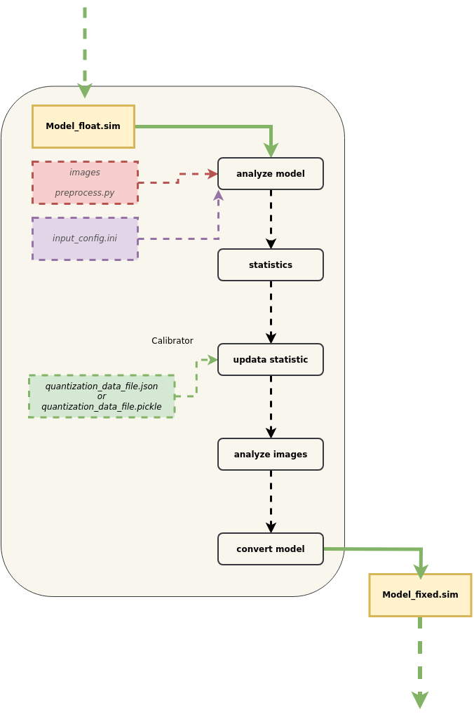
使用须知
① 为了兼容原有量化流程,原有量化所采用的策略依然进行。
② 获取Float模型tensor信息:原始模型在转成SGS_Float模型以后,一些算子会被合并和优化,计算图与原框架的模型有较大差异。所提供的量化文件内容需基于已转成的SGS_Float模型针对性调整,如Tensor名称等信息。为方便修改被合并和优化的层,可以使用calibrator_custom.calibrator的get_tensor_details方法获取Tensor的基本信息。可以获得每个Tensor的name,shape,dtype,qtype信息。
③ 获取Fixed模型tensor信息:转换好的fixed模型可以使用calibrator_custom.fixed_simulator的get_tensor_details方法获取Tensor的基本信息,可以获得每个Tensor的name,shape,min,max,quantization,dtype信息。
④ 根据模型Tensor信息,更新原始模型的量化文件后,即可导入量化数据文件。
⑤ 解析完量化文件后,会匹配已有量化信息与导入的量化信息。优先使用导入的量化信息,但不排除在合并时由于导入信息的不合理而放弃使用。
-
(1) 量化模型量化参数导出工具介绍
量化模型量化参数导出工具位置 SGS_IPU_Toolchain/Scripts/examples/save_quant_param.py
使用示例:
python3 save_quant_param.py \
-m fixed.sim \
--output_mode {JSON,Pickle}
使用须知
--output_mode参数支持JSON或Pickle格式量化参数数据的导出。
-
(2) 量化参数内容说明
-
Tensor的名字(name)[str]
-
算子类型提供对应数量的min,max。[list]
-
量化bit位。[int]
-
常量Tensor数据(data)(可选)[numpy.ndarray]
[
    {
        "name": "FeatureExtractor/MobilenetV2/Conv2d_0/weights",
        "min": [-4.555312, -2.876907, -1.234419],
        "max": [7.364561, 3.960804, 6.0],
        "bit": 8
    },
    {...},
    ...
]
-
(3) 量化规则说明
-
Conv2D的量化方法
① Conv2D的量化分为Inputs、Weights和Outputs,目前支持8bit,16bit量化。
② 如果使用8bit量化,Conv2D的输入为UINT8(相当于INT9的表达能力),Weights为INT8;如果使用16bit量化,Conv2D的输入和Weights均为INT16。
③ Weights的min和max值的个数由kernel的个数决定,输入和输出的min和max值的个数由输入输出的C维度决定。
④ 根据统计得到的Inputs、Weights和Outputs的min和max值,首先提前将Weights量化到定点数据,保存在fixed的网络内部,再在网络运行时动态量化输入和输出数据。
-
DepthwiseConv2D的量化方法
① DepthwiseConv2D的量化分为输入、Weights和输出,目前支持8bit,16bit量化。
② 如果使用8bit量化,DepthwiseConv2D的输入为UINT8(相当于INT9的表达能力),Weights为INT8;如果使用16bit量化,DepthwiseConv2D的输入和Weights均为INT16。
③ Weights、输入和输出的min和max值的个数均由对应Tensor的C维度决定。
④ 根据统计得到的输入、Weights和输出的min和max值,首先提前将Weights量化到定点数据,保存在fixed的网络内部,再在网络运行时动态量化输入和输出数据。
-
其他Op量化方法
① 网络中其他算子的量化min和max均基于C维度数量,仅支持16bit量化。
② 调用calibrator_custom.calibrator的get_tensor_details方法可以从qtype中得知该Tensor在定点模型时的data type。
-
4、calibrator_custom.SIM_Calibrator工具使用方法详解:
对于多输入、多段网络同时转换时,提供calibrator_custom.SIM_Calibrator,方便进行简单定义后,统一转换。calibrator_custom.SIM_Calibrator是已经实现好的class,当中只有forward方法未实现,使用时仅需实现该方法,即可转换完成。
下面以SGS_IPU_Toolchain/Scripts/examples/sim_calibrator.py为例,说明calibrator_custom.SIM_Calibrator的使用方法:
-
① 定义forward方法:
import calibrator_custom
class Net(calibrator_custom.SIM_Calibrator):
    def __init__(self):
        super().__init__()
        self.model = calibrator_custom.calibrator(model_path, input_config)
    def forward(self, x):
        out_details = self.model.get_output_details()
        self.model.set_input(0, x)
        self.model.invoke()
        result_list = []
        for idx in range(len(out_details)):
            result = self.model.get_output(idx)
            result_list.append(result)
        return result_list
使用须知
- forward的参数为模型输入,如有多个输入,可增加forward的参数。
-
② 创建calibrator_custom.SIM_Calibrator的实例:
net = Net() -
③ calibrator_custom.utils.image_preprocess_func使用预先定义好的前处理方法获取img_gen:
preprocess_func = calibrator_custom.utils.image_preprocess_func(model_name) def image_generator(folder_path, preprocess_func): images = [os.path.join(folder_path, img) for img in os.listdir(folder_path)] for image in images: img = preprocess_func(image) yield [img] img_gen = image_generator('./images', preprocess_func) -
④ 调用calibrator_custom.SIM_Calibrator的convert方法:
net.convert(img_gen, fix_model=[out_model_path])使用须知
-
convert方法必须输入两个参数:图片生成器、fixed.sim模型的保存路径list。
- 图片生成器(img_gen):③中生成,为方便多输入、多段网络转换模型,通过生成器方便组织输入图片的序列。如模型有多个输入,生成器应该按照定义forward时的输入顺序,返回有多个numpy.ndarray的list。
- fixed.sim模型的保存路径list: 如果在__init__中定义多个模型,fixed模型的保存路径list应该按照__init__中定义模型的顺序,依次命名。
-
convert方法其他可选参数:
- num_process: 进程数,同时运行的CPU数量
- quant_level: 选择量化等级:[L1, L2, L3, L4, L5],默认L5量化等级。
- quant_param: 量化导入参数。如果已有对应模型的量化参数,可以将量化的参数在模型转换中导入。
-
4.2.2.1 Calibrator客制化——分段网络转换示例
网络中有不支持的Layer,可将完整网络分段执行:
前一段网络运行完成后将结果输入给自定义实现层,
再将自定义层的输出结果作为第二段网络的输入运行。
以Faster_RCNN网络为例:
Faster_RCNN网络中的Proposal Layer是不支持的,需要将网络从该层分成两段。
- 1)网络切分
网络切分示意图:
(1) 图中的Python Layer是Proposal Layer,通过修改prototxt文件,将网络从Proposal Layer处拆成两段。
(2) 第一段网络将有3个输出,其中rpn_cls_prob_reshape和rpn_bbox_pred两个输出结果将作为Proposal Layer的输入,conv5_3和Proposal Layer的输出将作为第二段网络的输入。
(3) 第一段网络的输入是图片数据。
(4) 第二段网络的输入不是图片数据,可以对两个输入同时采用RAWDATA_S16_NHWC的格式配置。配置完成后,通过ConvertTool.py分别将两个网络转换成float.sim模型文件。
具体配置文件和转换命令
-
第一段网络:
python3 ~/SGS_IPU_Toolchain/Scripts/ConvertTool/ConvertTool.py caffe \ --model_file test_stageone.prototxt \ --weight_file VGG16_faster_rcnn_final.caffemodel \ --input_arrays data \ --output_arrays rpn_cls_prob_reshape,rpn_bbox_pred,conv5_3 \ --input_config input_config.ini \ --output_file faster_rcnn_main_float.sim设定conv5_3 这个输出的dequantizations 为FALSE,由于该输出直接输入第二段网络,所以在板端运行时不需要 转换成float,可以直接将该输出送进第二段网络。[INPUT_CONFIG] inputs=data; input_formats=BGR; quantizations=TRUE; mean=122.7717:115.9465:102.9801; std_value=1; [OUTPUT_CONFIG] outputs=rpn_cls_prob_reshape,rpn_bbox_pred,conv5_3; dequantizations=TRUE,TRUE,FALSE; -
第二段网络:
ROIPooling的rois输入维度为(N×5),当后段网络全部是InnerProduct时,N才可以设置为300(如上图所示),如果后段网络中有卷积时,N仅可以设置为1,第二段网络需要循环执行N次。
python3 ~/SGS_IPU_Toolchain/Scripts/ConvertTool/ConvertTool.py caffe \
--model_file second_stage.prototxt \
--weight_file VGG16_faster_rcnn_final.caffemodel \
--input_arrays conv5_3,rois \
--output_arrays cls_prob,bbox_pred \
--input_config input_config_stage2.ini \
--output_file faster_rcnn_stage2_float.sim
[INPUT_CONFIG] inputs=conv5_3,rois input_formats=RAWDATA_F32_NHWC,RAWDATA_F32_NHWC; quantizations=TRUE,TRUE; [OUTPUT_CONFIG] outputs=cls_prob,bbox_pred; dequantizations=TRUE,TRUE;
- 2)转换网络
路径SGS_IPU_Toolchain/Scripts/examples/caffe_faster_rcnn/faster_rcnn_calibrator.py下有Faster_RCNN网络转换工具demo,直接运行即可将两段网络直接转换成fixed模型。
(1) 指令
```
python3 ~/SGS_IPU_Toolchain/Scripts/examples/caffe_faster_rcnn/faster_rcnn_calibrator.py \
-i ~/SGS_Models/resource/detection/voc_calibration_set32/ \
-m0 faster_rcnn_main_float.sim \
-m1 faster_rcnn_stage2_float.sim \
--input_config0 input_config.ini \
--input_config1 input_config_stage2.ini
```
(2) 转换分段网络
- 首先定义网络的两段网络,再组织两段网络的运行方式,定义在forward方法里:
class Net(calibrator_custom.SIM_Calibrator):
    def __init__(self, main_model_path, main_input_config, second_model_path, second_input_config):
        super().__init__()
        self.main_model = calibrator_custom.calibrator(main_model_path, main_input_config)
        self.second_model = calibrator_custom.calibrator(second_model_path, second_input_config)
        self.rpn = rpn.ProposalLayer()
    def forward(self, x):
        out_details = self.main_model.get_output_details()
        input_data, im_scale = fill_inputImg2main(x)
        self.main_model.set_input(0, input_data)
        self.main_model.invoke()
        result_list = []
        for idx, _ in enumerate(out_details):
            result = self.main_model.get_output(idx)
            result_list.append(result)
        im_info = np.array([x.shape[0], x.shape[1], im_scale]).reshape(1, 3)
        bottom = [result_list[0], result_list[1], im_info]
        roi = self.rpn.forward(bottom)
        out2_details = self.second_model.get_output_details()
        self.second_model.set_input(0, result_list[2])
        self.second_model.set_input(1, roi)
        self.second_model.invoke()
        second_result = []
        for idx, _ in enumerate(out2_details):
            result = self.second_model.get_output(idx)
            second_result.append(result)
        return second_result
-
Faster_RCNN网络中,使用了自定义的rpn层,因此将第一段网络的第1个和第2个输出以及图片信息作为rpn层的输入,第一段网络的第3个输出和rpn层的输出roi作为第二段网络的输入。
-
最后调用Net的convert方法,同时生成两段网络的fixed模型。
net = Net()
net.convert(img_gen, num_process=num_subsets, fix_model=[out_main_model, out_second_model])
- 3)推演网络
路径SGS_IPU_Toolchain/Scripts/examples/caffe_faster_rcnn/faster_rcnn_simulator.py下有Faster_RCNN网络运行工具demo。
(1) 指令
python3 ~/SGS_IPU_Toolchain/Scripts/examples/caffe_faster_rcnn/faster_rcnn_simulator.py \
-i ~/SGS_Models/resource/detection/004545.jpg \
-m0 faster_rcnn_main_float.sim \
-m1 faster_rcnn_stage2_float.sim \
-t Float
(2) 运行两段模型的方法与转换网络时类似。
class Net(calibrator_custom.SIM_Simulator):
    def __init__(self, main_model_path, second_model_path, phase):
        super().__init__()
        if phase == 'Float':
            self.main_model = calibrator_custom.float_simulator(main_model_path)
            self.second_model = calibrator_custom.float_simulator(second_model_path)
            self.norm = True
        elif phase == 'Fixed':
            self.main_model = calibrator_custom.fixed_simulator(main_model_path)
            self.second_model = calibrator_custom.fixed_simulator(second_model_path)
            self.norm = False
        else:
            self.main_model = calibrator_custom.offline_simulator(main_model_path)
            self.second_model = calibrator_custom.offline_simulator(second_model_path)
            self.norm = False
        self.rpn = rpn.ProposalLayer()
    def forward(self, x):
        # Run main model
        out_details = self.main_model.get_output_details()
        input_data, im_scale = fill_inputImg2main(x, norm=norm)
        self.main_model.set_input(0, input_data)
        self.main_model.invoke()
        def forward(self, x):
            out_details = self.main_model.get_output_details()
            input_data, im_scale = fill_inputImg2main(x)
            self.main_model.set_input(0, input_data)
            self.main_model.invoke()
            result_list = []
            for idx, _ in enumerate(out_details):
                result = self.main_model.get_output(idx)
                result_list.append(result)
            im_info = np.array([x.shape[0], x.shape[1], im_scale]).reshape(1, 3)
            bottom = [result_list[0], result_list[1], im_info]
            roi = self.rpn.forward(bottom)
            out2_details = self.second_model.get_output_details()
            self.second_model.set_input(0, result_list[2])
            if self.norm:
                self.second_model.set_input(1, roi)
            else:
                self.second_model.set_input(1, roi)
            self.second_model.invoke()
            second_result = []
            for idx, _ in enumerate(out2_details):
                result = self.second_model.get_output(idx)
                second_result.append(result)
            return second_result
运行网络时先创建Net的实例,然后调用自身的方法就可以运行。
net = Net()
results = net(img_gen, num_process=num_subsets)
4.2.3 torch_calibrator工具详解
1、工具位置:SGS_IPU_Toolchain/Scripts/calibrator/torch_calibrator.py.
2、工具作用:对calibrator工具的补充。适用于以下场景:
-
模型参数量较小,使用calibrator工具无法达到满意的精度。
-
模型参数量较大,期待使用4bit量化减小模型大小。
3、工具优点:
torch_calibrator是基于Pytorch开发的新一代量化工具,与旧工具链相比,有以下特性
-
支持使用GPU,同等级的算法在GPU环境下量化速度更快(需配合使用Nvidia® GPU Docker);
-
支持4/8bit混合量化算法,对于有条件的模型在8bit量化的基础上继续向下压缩,进一步提高运行效率;
-
支持更复杂的量化标定算法,量化精度进一步得到提升,对小模型(mobilenet系列、shufflenet系列、nanodet系列等)提升效果更为明显。
4、使用示例:
python3 torch_calibrator.py \
-i ilsvrc2012_calibration_set100 \
-m caffe_mobilenet_v2_float.sim \
--input_config input_config.ini \
--quant_config quant_config.yaml \
-n caffe_mobilenet_v2.py \
-q Q2 \
--soc_version CHIP
5、参数说明:
(1) 必选参数
-
-i,--image: 标定数据集图像路径,100张训练图片。 -
-m,--model: 浮点网络模型文件路径。 -
--input_config: input_config.ini文件路径。 -
--quant_config: 量化参数(yaml格式)文件路径,后面会详细介绍该文件的配置方法和用途。 -
-n,--preprocess: 模型预处理文件路径。 -
-q,--q_mode: 量化选项,后面会详细介绍。 -
--soc_version: IPU Toolchain chip
使用须知
- 执行python3 SGS_IPU_Toolchain/DumpDebug/show_sdk_info.py 可查看IPU Toolchain具体适配那些chip及版本信息
(2) 可选参数
-
-o,--ouptut: 模型输出路径。 -
--cal_batchsize: 标定数据集的batchsize,一般情况下等于数据集个数。
使用须知
- 如果标定数据集十分庞大或模型结构特殊无法在batchsize != 1的情况下推理,则可以设置这个参数。默认为100。
torch_calibrator配置文件 quant_config.yaml 详解
与calibrator工具相比,torch_calibrator工具还需要配置量化参数(yaml格式)文件。
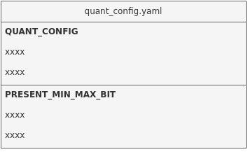
文件内容展示:
QUANT_CONFIG:
  retrain_iter_num: 40
  device: 'cuda:0'
  mixed_precisions: [4, 8]
  use_preset_min_max_bit: 0
  mp_rate: 0.6

PRESET_MIN_MAX_BIT: # preset tensor min/max and bit
  [
    {name: "126", min: null, max: null, bit: 8},
    {name: "layer1.0.conv1.weight", min: null, max: null, bit: 8}
  ]
文件内容说明
-
retrain_iter_num:每层重训练迭代次数
如果该项不写则默认为40,部分轻量级模型可能需要更多的迭代次数。
-
device:指定GPU/CPU
如果不给则会自动寻找空闲的GPU。若无GPU则会自动调用CPU。
若指定cpu运算,填写为'cpu'即可。
-
use_preset_min_max_bit:是否使用手工预设的min/max/bit信息
如果该项为1,则会使用下方手动设置的信息;如果该项为0或不写,则不会使用下方的信息。
-
mixed_precisions: 混合量化模式
可选[4, 8],[8, 16]。
如果不填,在Q13的模式时默认是[4, 8];Q23的模式时默认是[8, 16]。 -
mp_rate:混合量化指定的压缩率
当
mixed_precisions指定为[4, 8]时,mp_rate指定在[0.25, 0.5)的范围内(不包括0.5)。
当mixed_precisions指定为[8, 16]时,mp_rate指定在[0.5, 1]的范围内。
不填写该参数则会自动推荐一个压缩率。该参数会配合mixed_precisions,生成4/8bit或8/16bit的模型。仅在Q13、Q23的模式下生效。建议使用Q13或Q23时先不配置
mp_rate,让torch_calibrator运行后得到自动推荐的压缩率。如果自动推荐的压缩率满足精度要求,可通过以0.05步长下调压缩率,满足精度要求的同时提升模型性能。
如果自动推荐的压缩率不满足精度要求,可通过以0.05步长上调压缩率,提升模型量化精度。
-
PRESET_MIN_MAX_BIT:可以预设某个Tensor的min/max/bit信息
Tensor名字以float.sim模型中为准。需要将
use_preset_min_max_bit设为1。
torch_calibrator量化参数 -q / --q_mode 详解
| 量化等级 | 量化特色说明 | 量化子选项 | 详细说明 |
|---|---|---|---|
| Q1 | 仅做min和max的标定,不会优化卷积参数,速度整体较快,适用于没有GPU的环境,如果有GPU则可以加快标定速度;精度方面整体持平calibrator量化的精度; | Q10 | 全16bit量化,量化精度与float32模型基本一致 |
| Q1/Q11 | 全8bit快速量化,量化精度与L2模式相当 | ||
| Q12 | 自适应8bit和16bit量化,量化精度与L5模式相当 | ||
| Q13 | 8/16bit(4/8bit 可根据配置文件更改,默认8/16bit)混合量化,对于有进一步压缩需求的模型可以选用此方式。 | ||
| Q2 | 量化等级会对模型进行逐层优化,低bit情况下精度提升明显,在轻量级模型效果更为显著,适用于有单块GPU的环境;精度上整体优于Q1 | Q20 | 全16bit量化,量化精度与float32模型基本一致 |
| Q21 | 全8bit量化,在一些小模型上能够获得更好的效果 | ||
| Q2/Q22 | 自适应选择量化方式,是目前效果最好的量化方式,生成的定点模型为全8bit量化或接近全8的8/16混合量化。 | ||
| Q23 | 8/16bit(4/8bit 可根据配置文件更改,默认8/16bit)混合量化,可以进一步压缩模型,压缩程度和精度均优于Q13 |
4.3. 阶段三:Compiler工具生成离线网络模型详解
本节介绍如何使用Compiler工具将SGS定点模型转换到SGS端侧模型。
1、工具位置:SGS_IPU_Toolchain/Scripts/calibrator/compiler.py.
2、工具作用:将模型转换为SGS端侧模型。
3、使用示例:
以转换ONNX框架的模型为例:
python3 ~/SGS_IPU_Toolchain/Scripts/calibrator/compiler.py
-m ~/SGS_Models/onnx/onnx_yolov8s/onnx_yolov8s_fixed.sim
--soc_version CHIP
4、参数说明:
(1) 必选参数
-
①
-m,--model: Fixed网络模型文件路径。 -
②
--soc_version: IPU Toolchain chip
使用须知
- 执行python3 SGS_IPU_Toolchain/DumpDebug/show_sdk_info.py 可查看IPU Toolchain具体适配那些chip及版本信息
(2) 可选参数:
-
①
-b,--batch:期待设定的Batch数,默认为1。 -
②
--batch_mode:多batch模式。
使用须知
-
可选n_buf/one_buf,默认为n_buf模式
-
n_buf: 每个batch的输入和输出数据独立buffer。- 选择该模式时,
-b/--batch参数为期待设定的最大Batch数,Compiler会根据最大Batch数优化,生成的离线模型可使用任意小于最大Batch数运行。
- 选择该模式时,
-
one_buf: 多个batch的数据需在最高维度堆叠后使用一块buffer。- 选择该模式时,
-b/--batch参数可指定多种需要使用的Batch数,以逗号( , )分隔,最多设定10个,生成的离线模型仅能使用指定Batch数运行。
- 选择该模式时,
- ③
-c,--category: 模型的类别。
使用须知
-
可选Classification / Detection / Unknown。
Classification: 模型有1个输出,会根据输出排序输出分数由高至低的前5个。Detection: 模型有4个输出,会根据输出转换为输入图片的bbox位置以及类别。只支持IPU后处理算子[后处理模块]。其他后处理请使用Unknown。Unknown: 模型输出不属于上述两种类型,会输出全部的Tensor数值。定点网络模型转换到离线网络模型时默认为Unknown。
- ④
-o,--output: 模型输出路径。
使用须知
-
指定离线网络模型输出数据位置:指定到文件夹,将自动以网络模型文件前缀命名,后接sgsimg.img;
-
指定到具体路径和文件名,将以指定路径和文件名命名离线网络模型;
-
不指定该参数,将以网络模型文件路径储存离线网络模型。